TV RGB mod thread

The place for all discussion on gaming hardware
MarkOZLAD
Posts: 1024
Joined: Thu May 18, 2017 12:39 pm

Re: TV RGB mod thread

Post by MarkOZLAD »

reminiz wrote: Fri May 30, 2025 3:27 am
buttersoft wrote: Wed Nov 23, 2016 5:53 am In fact, I'd love some advice for modding a Samsung HiTron TV-488. I'm not having any luck finding the service manual, but it uses this Philips IC (TDA8841) - https://my.mixtape.moe/hiflqk.pdf.
Hi Buttersoft, I’m also in Australia. I have acquired a TV-348 (14” Samsung) which composite in/out on the back.

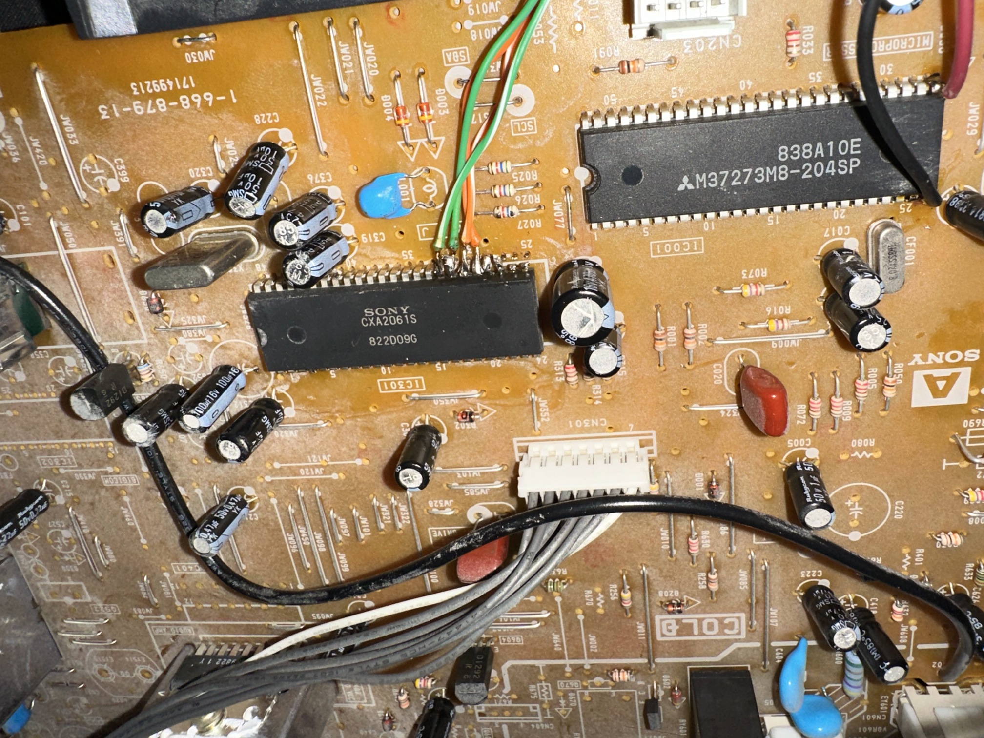
It also uses the same Philips jungle IC. 4481. Does this mean my set will also have RGB disabled in the EEPROM?
What’s the easiest way to test this?

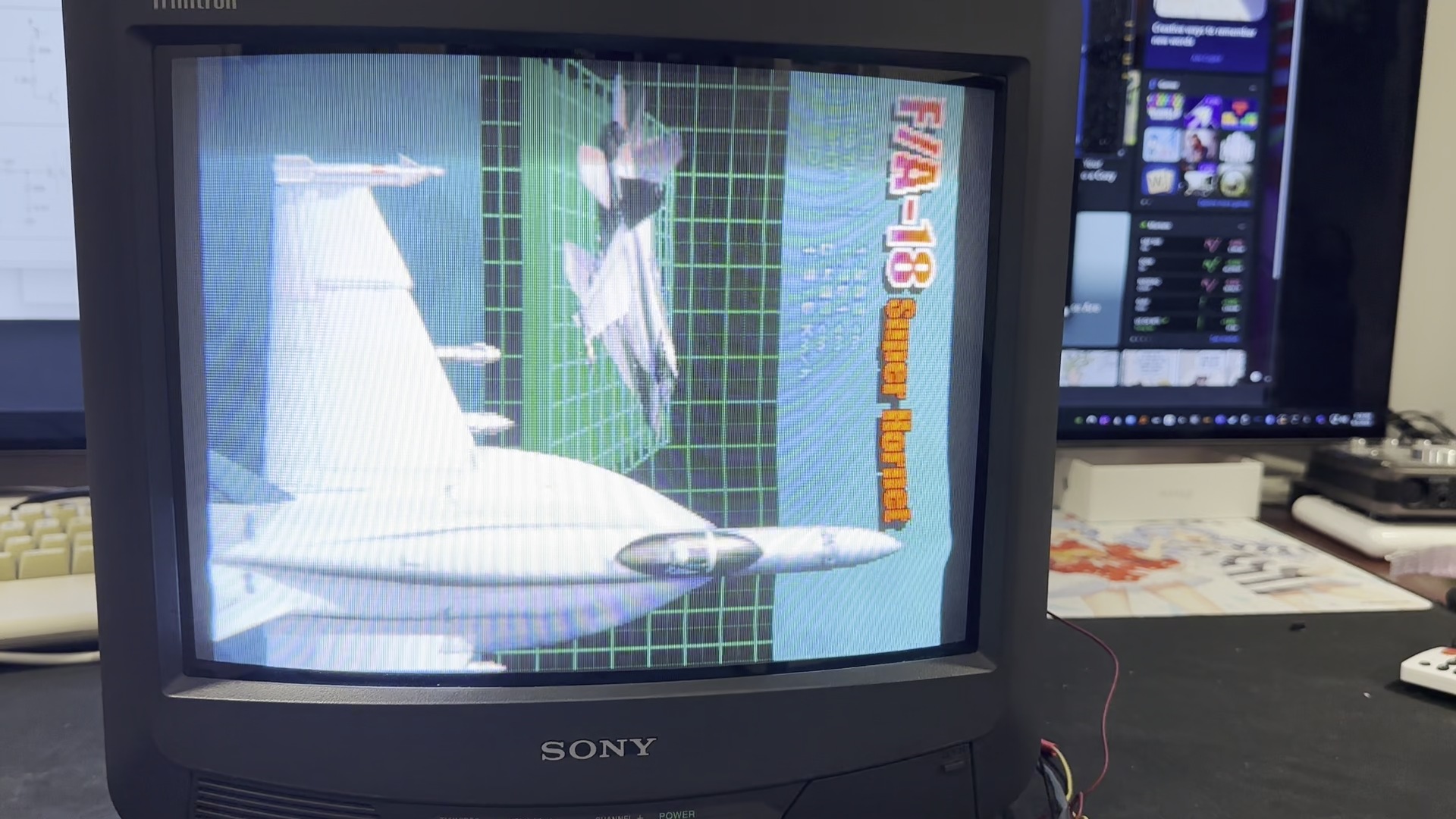
It seems like the component plugs are soldered into a SCART pin-out on the PCB. If RGB is active, would this mean a simple desolder and swap in a SCART plug?

Any insight would be great 🙏
The set needs to have the scart option set in the service menu.

After that it is a matter of soldering in the scart port and connecting the dots based on schematics.
___________________________________________________
MarkOZLAD
OSD/External RGB Mux Diagram
OSD/External RGB Mux Resistor Value Table 0.7Vp-p : 0.5Vp-p

"Imagine toggle switch OSD modding a TV in 2019" - maxtherabbit
ElectroGehirn
Posts: 5
Joined: Fri May 30, 2025 12:06 pm

Re: TV RGB mod thread

Post by ElectroGehirn »

Hello guys, i am new here, just want to ask where i could reach out for help with my philips 19pt825b/00 - fl4.26, not for modding, better said finding a way to get it working again. i was tring watch my vhf signal on air and then it made a poof sound (no cap is broken as it looks rn) and it wont turn on anymore, just showing its red led and giving up when i want to turn it on
alamone
Posts: 740
Joined: Wed Mar 09, 2011 10:32 pm

Re: TV RGB mod thread

Post by alamone »

Hi, I'm attempting to RGB mod a Sony KV-13M40, it appears to use "BA-4" chassis, the jungle is Sony CXA2061S, the microprocessor is M37273M8.
At the moment, I want to just do a simple mod of replacing the OSD with RGB input without trying to do a mux of the OSD.

I was finally able to get a picture, but the sync is unstable (wavy lines) and there is noise from the OSD.
I lifted the RGB input pins on the jungle, which are connected via 0.01uF caps to RGB output from supergun.
I previously tried connecting these RGB lines to GND via 75 ohm resistors as stated in OP, but this caused the image to be very dark and blurry, so I removed the resistors.
Composite sync is connected to composite video input via 0.01uF cap and 470ohm resistor.
+5V and GND are taken from pins 26 and 27 of the M37273M8.
+5V is tied to YS pin on the jungle via 10k resistor.

Picture from supergun. Note the wavy sync at nose of the plane:
Image

Picture when YS pin enabled and no video input. Note that you can see "Video 1" text clearly:
Image

Wiring to jungle (RGB input and Ys) and microprocessor (+5V and GND):
Image

Am I missing something to stabilize the sync and remove the OSD noise? Thanks for any help.
alamone
Posts: 740
Joined: Wed Mar 09, 2011 10:32 pm

Re: TV RGB mod thread

Post by alamone »

I was able to fix the OSD ghosting problem by adding back the 75 ohm resistors to GND (I had soldered them in the wrong place, after the caps instead of before the caps).
However I'm having a problem where the screen filckers or blinks around every 2 seconds or so. I posted a video, capturing first with no signal but Ys pin on, and then with signal.

https://youtu.be/HjK6mj7zCkQ
alamone
Posts: 740
Joined: Wed Mar 09, 2011 10:32 pm

Re: TV RGB mod thread

Post by alamone »

This time instead of connecting CSYNC to the composite input jack, I lifted pin 4 (CVBS) on the jungle and connected it to CSYNC via a 0.01uF cap and 75 (well 83 since I don't have 75) ohm resistor to GND.
That resolved the periodic blinking, but now I'm getting periodic snow, and also some jailbar interference patterns as shown in the video.

https://youtu.be/_OKz93dmdv4

Almost working, but not quite...
alamone
Posts: 740
Joined: Wed Mar 09, 2011 10:32 pm

Re: TV RGB mod thread

Post by alamone »

OK, I fixed the snow, 5V to the YS pin is apparently too high, I used a voltage divider to reduce to 2.5V and now there are no more artifacts in the signal. For the wavy picture, I was able to reduce the problem by lowering the brightness pot from the HAS. So I finally got it working, next I might try to do a mux mod.

https://x.com/alamone/status/1929657195056205841
Muzzy011
Posts: 1
Joined: Mon Jun 02, 2025 10:25 pm

Re: TV RGB mod thread

Post by Muzzy011 »

rovertech21 wrote: Sun May 26, 2024 4:10 pm
rovertech21 wrote: Fri May 24, 2024 11:02 am Hello all! I recently picked up a couple of RF only sets and have been researching RGB modding them. One is an early 90s Magnavox RR1939C421 that seems to be hot chassis but the other is a newer Sanyo AVM-2508G that looks promising.

The closest manual I can find is https://elektrotanya.com/sanyo_avm-2507 ... nload.html but it appears to be the use the same PCB and ICs. The Jungle IC is LA76070N https://www.scribd.com/doc/202370624/LA76070N .

I checked for resistance between the terminals on the AC plug and the shield around the tuner on the board and it was reading about 0.7 M ohms. It also appears to have a hot "Power" area circled off in the masking on the PCB around the power supply components.

Does this seem like a hot chassis unit or does it look ok to proceed with experimentation? Any additional items I can check to rule out hot chassis? Thanks in advance!
For anyone that finds this in the future, it does seem that this set can be modded (best I can tell its not hot chassis but do your own research before attempting!!!) but unfortunately I damaged it during the process. After some preliminary testing I took the board out again to add diodes to the RGB lines and when going back together I accidentally plugged the degauss coil into the wrong plug (an identical header near the back of the board) and now the image is distorted and black on one side.

Picture of what it looks like now and where on the board I made the mistake - https://imgur.com/a/88660Tt Does it look like a lost cause at this point?

Edit - Its not dead! I was testing it without the grounding resistors added back into the circuit and didn't realize how bad it would look with those missing. Still can't get composite in working but going to wait on additional parts before continuing testing.
Did you ever make it work? I got an exact TV in very good condition, with very good geometry. I also found this link https://sector.sunthar.com/guides/crt-r ... m2507.html, but I can't figure it out. I am not a stranger to electronics, but this is my first TV MOD
gabrielgamer99
Posts: 4
Joined: Thu Sep 21, 2023 9:56 pm

Re: TV RGB mod thread

Post by gabrielgamer99 »

https://imgur.com/a/XHx8pct

Has anybody seen video interference like this with an rgb mod?

I did an rgb mod on a Mickey Mouse tv and occasionally off and on I’ll get video noise only on the bottom half of the screen, like what’s posted in the photo

I tried my best to follow the path in the photos of the guide, I even went ahead and shielded all the wiring with copper tape, grounding the copper tape, then covering it with harness tape, which I think improved it somewhat

Using snes with high quality scart cables, issue also appears on Saturn rgb (would test with more but don’t have money for good scart cables and no good supplier in Canada)

Issue only appears on rgb, composite looks fine

The author of the original guide didn’t seem to use any fancy cables so not sure why I’m having issues unless a particular cap is bad but doesn’t show up anywhere else

Looking for answers, can probably use as is but if it’s not hard would like to make it so there’s no noise

(Have done two other rgb mods and haven’t had issues like this before)

Thanks for reading!

https://sector.sunthar.com/guides/crt-r ... 1350c.html

Guide I followed
alamone
Posts: 740
Joined: Wed Mar 09, 2011 10:32 pm

Re: TV RGB mod thread

Post by alamone »

Here's a video of the finished RGB mod for the Sony KV-13M40.

https://x.com/alamone/status/1931854355461963833

I'm using a VGA connector for RGB, I hate bulky SCART ports.

I tried to convert it to a MUX mod. While the OSD does display, it's very faint, but I don't really need to use the OSD much so I'm going to leave it as-is.
Delphius
Posts: 5
Joined: Tue Mar 25, 2025 3:58 pm

Re: TV RGB mod thread

Post by Delphius »

Emerson HKTV13 / Hello Kitty TV RGB Mod Update

Just want to give an update on the HKTV13 I was working on. It was a lot of work but I was able to successfully add RGB and find a proper solution around the dual OSD / Switch buffer circuit. I had to isolate them entirely and create my own circuit board with a switching component that 2:1 from the external RGB and the original composite / OSD circuit. I also ended up needing to add an RGB amplifier for the external RGB to give it enough boost to work properly into the jungle chip. It looks pretty damn good and the levels seem spot on so far.

Image
Image
Image
Image

I may release the circuit in the future after I am finished with it. Overall it is pretty non destructive as sort of an interposer board using the wiring harness to inject the signals. I did replace the harness with modern JST connectors to make it more compatible. Next up will be drilling out the holes in the shell for the RCA jacks and switch.
MarkOZLAD
Posts: 1024
Joined: Thu May 18, 2017 12:39 pm

Re: TV RGB mod thread

Post by MarkOZLAD »

Delphius wrote: Thu Jun 19, 2025 8:57 pm I may release the circuit in the future
I for one would love to see the circuit.

Great job.
___________________________________________________
MarkOZLAD
OSD/External RGB Mux Diagram
OSD/External RGB Mux Resistor Value Table 0.7Vp-p : 0.5Vp-p

"Imagine toggle switch OSD modding a TV in 2019" - maxtherabbit
Anonygoose
Posts: 38
Joined: Thu May 08, 2014 7:55 pm
Location: UAE

Re: TV RGB mod thread

Post by Anonygoose »

Looking to RGB mod this Sanyo set (A8-A chassis).

I can see RGB pins from the jungle going to the teletext connector (have not opened CRT yet, not sure if Teletext is populated).

Do I simply inject RGB here and add 75ohm and .1uf caps?

Image

Edit: Opened up the CRT. Teletext is not populated and the 3 1k ground resistors aren't there. So from my understanding I need to populate 75ohm resistors in there, wire blanking to a voltage source along with a switch and I should be good to go. Blanking voltage 2.5-3v (?). Please correct me if I'm wrong.
Last edited by Anonygoose on Mon Jun 23, 2025 1:21 pm, edited 2 times in total.
esnc68
Posts: 1
Joined: Mon Jun 23, 2025 6:06 am

Re: TV RGB mod thread

Post by esnc68 »

Anyone know if I can RGB mod this Panasconic ct-27g24a from 1999?

https://imgur.com/a/crt-pana-2ODwzyX

Is this TV worth RGB modding and can it work good? I tried searching myself. I think I heard somewhere that some Panasonics have a "bump" effect with RGB mod. I was hoping it wasn't the case with this tv. But if so, would it be too bad to be worth it?

And my questions about doing these mods are:

1. I kind of want to do a Scart input. Because I heard it is a little better than component for RGB and sharper. Is that right?

2. If I do scart, will it be able to connect to the tv speakers?

3. Would that be better than AV sound?

I don't know anything about doing this or EE in general, so I was thinking of asking my neighbor to do this.

Anyone have any recommendations or advice to do this? I would love to do this! I love these older round tube tvs the most and I absolutely want to see my games in RGB on it!! I was also thinking of connecting an emulator computer (CRT Emudriver stuff). Or a mister when I get one in the future.

Thank you so much!!
MarkOZLAD
Posts: 1024
Joined: Thu May 18, 2017 12:39 pm

Re: TV RGB mod thread

Post by MarkOZLAD »

Anonygoose wrote: Sun Jun 22, 2025 8:48 pm Edit: Opened up the CRT. Teletext is not populated and the 3 1k ground resistors aren't there. So from my understanding I need to populate 75ohm resistors in there, wire blanking to a voltage source along with a switch and I should be good to go. Blanking voltage 2.5-3v (?). Please correct me if I'm wrong.
That’s what I’d do.

For the blanking I’d make sure the 1K pulldown is in place for it and then run 5V through a 1K to a switch and then into the blanking. That’ll give you 2.5V.
___________________________________________________
MarkOZLAD
OSD/External RGB Mux Diagram
OSD/External RGB Mux Resistor Value Table 0.7Vp-p : 0.5Vp-p

"Imagine toggle switch OSD modding a TV in 2019" - maxtherabbit
Anonygoose
Posts: 38
Joined: Thu May 08, 2014 7:55 pm
Location: UAE

Re: TV RGB mod thread

Post by Anonygoose »

MarkOZLAD wrote: Tue Jun 24, 2025 7:31 am
Anonygoose wrote: Sun Jun 22, 2025 8:48 pm Edit: Opened up the CRT. Teletext is not populated and the 3 1k ground resistors aren't there. So from my understanding I need to populate 75ohm resistors in there, wire blanking to a voltage source along with a switch and I should be good to go. Blanking voltage 2.5-3v (?). Please correct me if I'm wrong.
That’s what I’d do.

For the blanking I’d make sure the 1K pulldown is in place for it and then run 5V through a 1K to a switch and then into the blanking. That’ll give you 2.5V.
I found a full unpopulated scart circuit 🤣

Image

Schematics didn't show this. I'll try populate this
MarkOZLAD
Posts: 1024
Joined: Thu May 18, 2017 12:39 pm

Re: TV RGB mod thread

Post by MarkOZLAD »

Anonygoose wrote: Tue Jun 24, 2025 7:56 am I found a full unpopulated scart circuit 🤣

Image

Schematics didn't show this. I'll try populate this
I would do the same. Perhaps look for schematics/service manuals for sets with same or similar chassis.
___________________________________________________
MarkOZLAD
OSD/External RGB Mux Diagram
OSD/External RGB Mux Resistor Value Table 0.7Vp-p : 0.5Vp-p

"Imagine toggle switch OSD modding a TV in 2019" - maxtherabbit
Post Reply