Hi, I haven't seen a AA-1A done. I've studied the BA-5 mods, and this one looks different. I'm used to seeing OSD go into the jungle, but I think the tap point here would be closed captioning. I don't care about that, would I even need to bother with a switch or muxing?
https://ibb.co/VN1tvCN
TV RGB mod thread
-
Spud
- Posts: 9
- Joined: Tue Dec 10, 2019 4:58 am
Re: TV RGB mod thread
Last edited by Spud on Tue Apr 28, 2020 3:43 am, edited 1 time in total.
-
MarkOZLAD
- Posts: 1040
- Joined: Thu May 18, 2017 12:39 pm
Re: TV RGB mod thread
The only way to do it is to hijack the Close Captioning RGB because the OSD RGB is a digital input.Spud wrote:Hi, I haven't seen a AA-1A done. I've studied the BA-5 mods, and this one looks different. I'm used to seeing OSD go into the jungle, but I think the tap point here would be closed captioning. I don't care about that, would I even need to bother with a switch or muxing?
https://ibb.co/VN1tvCN
Can do a Closed Caption Mux if you want or likely you can remove the Close Captioning Chip/snip the lines. Would likely only put a switch for blanking.
___________________________________________________
MarkOZLAD
OSD/External RGB Mux Diagram
OSD/External RGB Mux Resistor Value Table 0.7Vp-p : 0.5Vp-p
"Imagine toggle switch OSD modding a TV in 2019" - maxtherabbit
MarkOZLAD
OSD/External RGB Mux Diagram
OSD/External RGB Mux Resistor Value Table 0.7Vp-p : 0.5Vp-p
"Imagine toggle switch OSD modding a TV in 2019" - maxtherabbit
-
Spud
- Posts: 9
- Joined: Tue Dec 10, 2019 4:58 am
Re: TV RGB mod thread
I'm a little fuzzy on syncs. I'm using a Wii that I have softmodded, and I plan to shift it to pal and use a scart cable. If I get a CSync cable, I can put csync into the svideo pin?
-
MarkOZLAD
- Posts: 1040
- Joined: Thu May 18, 2017 12:39 pm
Re: TV RGB mod thread
Most likely will work. It's normally a suck it and see approach. Results vary.Spud wrote:I'm a little fuzzy on syncs. I'm using a Wii that I have softmodded, and I plan to shift it to pal and use a scart cable. If I get a CSync cable, I can put csync into the svideo pin?
___________________________________________________
MarkOZLAD
OSD/External RGB Mux Diagram
OSD/External RGB Mux Resistor Value Table 0.7Vp-p : 0.5Vp-p
"Imagine toggle switch OSD modding a TV in 2019" - maxtherabbit
MarkOZLAD
OSD/External RGB Mux Diagram
OSD/External RGB Mux Resistor Value Table 0.7Vp-p : 0.5Vp-p
"Imagine toggle switch OSD modding a TV in 2019" - maxtherabbit
-
t0nito
- Posts: 1
- Joined: Thu Apr 30, 2020 3:59 pm
Re: TV RGB mod thread
Hi as a European reading all of these RGB mods, may I ask, why do you use a external switch? There is no need to.
The way our TVs work here is when you have an RGB enabled device the device sends the 3V blanking voltage through pin 16 on the SCART plug. There is also a signaling pin that makes the TV switch to AV on its own when you turn on the device but it's unnecessary you can just switch to AV (video in) on the remote.
So instead of supplying the 3V to the jungle IC from a voltage source in the TV with a manual switch why not just let the device switch it on for you like our TVs here? I think it makes a much nicer setup instead of having to reach for a switch.
-
lopazopy
- Posts: 7
- Joined: Sat May 02, 2020 7:27 pm
Re: TV RGB mod thread
Need some help figuring out if RGB is possible on this set. I picked up a Sharp 20A-M100 and the datasheets I can find are fuzzy at best. The TV is RF input only, so I was wondering if I could RGB it and add a composite for the syncing. All help is greatly appreciated.
Top side of board showing IC201 ( X1712CE ) and IC1001 ( X1709CE )

IC201 ( X1712CE ) I see pins 19 and 20 going to OSD I/F, but that is only two pins. I also see 15, 16, 17, and 18 are the RGB going out to the tube, but that doesn't help me.

IC1001 ( X1709CE )

Top side of board showing IC201 ( X1712CE ) and IC1001 ( X1709CE )
IC201 ( X1712CE ) I see pins 19 and 20 going to OSD I/F, but that is only two pins. I also see 15, 16, 17, and 18 are the RGB going out to the tube, but that doesn't help me.
IC1001 ( X1709CE )
Last edited by lopazopy on Wed May 06, 2020 6:44 pm, edited 1 time in total.
-
skum
- Posts: 107
- Joined: Tue May 08, 2018 6:34 pm
- Location: Denmark
Re: TV RGB mod thread
RGB does not necessarily equal SCART. Many tend to use the easier to mount BNC, which thus requires a separate switch. Also, as I remember learned by superg during gscartsw development, many SCART plugs aren't necessarily wired for this, at least not when homemade. In Europe we more or less have zip of these "issues" which is also why I do use the blanking pin in my mods, but US *is* vastly different in this context.t0nito wrote:Hi as a European reading all of these RGB mods, may I ask, why do you use a external switch? There is no need to.
The way our TVs work here is when you have an RGB enabled device the device sends the 3V blanking voltage through pin 16 on the SCART plug. There is also a signaling pin that makes the TV switch to AV on its own when you turn on the device but it's unnecessary you can just switch to AV (video in) on the remote.
So instead of supplying the 3V to the jungle IC from a voltage source in the TV with a manual switch why not just let the device switch it on for you like our TVs here? I think it makes a much nicer setup instead of having to reach for a switch.
EDIT: Some people also tend to not liking supplying the blanking voltage as they feel supplying this increases risk of damaging the supplying console. I however find this somewhat silly, as using a 1K+ resistor and a diode or smth on the blanking line will dramatically reduce risks here.
-
Spud
- Posts: 9
- Joined: Tue Dec 10, 2019 4:58 am
Re: TV RGB mod thread
Hi, working on my 32XBR85. I have the service manual but can't find the data sheet for the IC301 cXA1477as. In the service manual it has a black box diagram of the IC301 and it actually has TWO sets of RGB inputs, which I'm not used to seeing. Pins 16-18 are labeled "LR,LG,LB" and are the closed caption input. They have .1uf caps in series. The OSD is pins 19-21, are labeled "DR,DG,DB" and have 220R in series. Can someone demistify what is the best course here? Is my guess that the D denotes digital correct and that the closed caption is the better course of action?
-
maxtherabbit

- Posts: 1763
- Joined: Mon Mar 05, 2018 4:03 pm
Re: TV RGB mod thread
L could mean "linear" which would be good (analog)Spud wrote:Hi, working on my 32XBR85. I have the service manual but can't find the data sheet for the IC301 cXA1477as. In the service manual it has a black box diagram of the IC301 and it actually has TWO sets of RGB inputs, which I'm not used to seeing. Pins 16-18 are labeled "LR,LG,LB" and are the closed caption input. They have .1uf caps in series. The OSD is pins 19-21, are labeled "DR,DG,DB" and have 220R in series. Can someone demistify what is the best course here? Is my guess that the D denotes digital correct and that the closed caption is the better course of action?
-
skum
- Posts: 107
- Joined: Tue May 08, 2018 6:34 pm
- Location: Denmark
Re: TV RGB mod thread
The cap in front gives away it is meant for an ac signal, so an "analog" signal, thus this would be where you wanna inject. I guess a mux is in order, if there's a CC circuit.Spud wrote:Hi, working on my 32XBR85. I have the service manual but can't find the data sheet for the IC301 cXA1477as. In the service manual it has a black box diagram of the IC301 and it actually has TWO sets of RGB inputs, which I'm not used to seeing. Pins 16-18 are labeled "LR,LG,LB" and are the closed caption input. They have .1uf caps in series. The OSD is pins 19-21, are labeled "DR,DG,DB" and have 220R in series. Can someone demistify what is the best course here? Is my guess that the D denotes digital correct and that the closed caption is the better course of action?
-
Spud
- Posts: 9
- Joined: Tue Dec 10, 2019 4:58 am
Re: TV RGB mod thread
Do I have to mux? I have no interest in the closed caption.
Here's the block diagram. Closed caption on the bottom. Any clues here? Is YS blanking?
https://ibb.co/F5zMXmk
Here's the block diagram. Closed caption on the bottom. Any clues here? Is YS blanking?
https://ibb.co/F5zMXmk
Last edited by Spud on Sun May 03, 2020 11:58 pm, edited 2 times in total.
-
flynnsbit
- Posts: 53
- Joined: Sun Apr 12, 2020 4:57 pm
Re: TV RGB mod thread
So I have this same CXA1865S in my Sony KV-13m10 and it has RGB In lines on 16 17 and 18. Do I need to seperate these from the 3.4 that is referenced in the red box below? I have RGB going in with the normal 75 resistor + 1uf Capacitor and I get a very very faint image with no color or green/red color bars. I soldered to the bottom side of 16-18 so I am wondering if wha I highlighted in red is screwing me up.Syntax wrote:Or you could try doing it properly and putting your RGB signal into pins 15 through 18.
God knows why you decided to do an OSD switch on a set that has external RGB inputs... Oh yeah that crappy first post...
https://i.imgur.com/gOU5321.png
Service Manual for reference: https://www.manualslib.com/download/948 ... 13m10.html
Should I just desolder 16-18 , leave them de-soldered and then come in from the top? It looks like those three are fully bridged on the board unless I am crazy
Picture:

Last edited by flynnsbit on Mon May 04, 2020 12:21 am, edited 1 time in total.
-
maxtherabbit
- Posts: 1763
- Joined: Mon Mar 05, 2018 4:03 pm
Re: TV RGB mod thread
There may not even be a closed caption decoder circuit present. You don't have to mux in either case, just cut the existing inputs if there are anySpud wrote:Do I have to mux? I have no interest in the closed caption.
Here's the block diagram. Closed caption on the bottom. Any clues here? Is YS blanking?
https://ibb.co/F5zMXmk
Ys is your fast blanking you will want to use. (Ym is half tone blanking)
-
MarkOZLAD
- Posts: 1040
- Joined: Thu May 18, 2017 12:39 pm
Re: TV RGB mod thread
I've not seen such close up views of solder blobs before.
___________________________________________________
MarkOZLAD
OSD/External RGB Mux Diagram
OSD/External RGB Mux Resistor Value Table 0.7Vp-p : 0.5Vp-p
"Imagine toggle switch OSD modding a TV in 2019" - maxtherabbit
MarkOZLAD
OSD/External RGB Mux Diagram
OSD/External RGB Mux Resistor Value Table 0.7Vp-p : 0.5Vp-p
"Imagine toggle switch OSD modding a TV in 2019" - maxtherabbit
-
flynnsbit
- Posts: 53
- Joined: Sun Apr 12, 2020 4:57 pm
Re: TV RGB mod thread
Lol, I distracted you with my picture so much that I didn't get an answer. It's a realitively cheap digital microsope from Amazon that I use to check my work and so I can see what I am soldering.MarkOZLAD wrote:I've not seen such close up views of solder blobs before.
-
Spud
- Posts: 9
- Joined: Tue Dec 10, 2019 4:58 am
Re: TV RGB mod thread
There IS a closed caption circuit, and it looks like it has 5.6k's in series. Soooo.... It seems like it would be fine to just follow your mux method, no?There may not even be a closed caption decoder circuit present. You don't have to mux in either case, just cut the existing inputs if there are any
Ys is your fast blanking you will want to use. (Ym is half tone blanking)
The only quirk appears to be that the CC circuit doesn't send blanking. The YS comes from another line that is built up from inputs all over the place. There isn't a simple 3.9k in series. How do I deal with that?
-
maxtherabbit
- Posts: 1763
- Joined: Mon Mar 05, 2018 4:03 pm
Re: TV RGB mod thread
you can mux with the CC decoder if you like, but I thought you said you don't care about CC functionality?Spud wrote:There IS a closed caption circuit, and it looks like it has 5.6k's in series. Soooo.... It seems like it would be fine to just follow your mux method, no?There may not even be a closed caption decoder circuit present. You don't have to mux in either case, just cut the existing inputs if there are any
Ys is your fast blanking you will want to use. (Ym is half tone blanking)
The only quirk appears to be that the CC circuit doesn't send blanking. The YS comes from another line that is built up from inputs all over the place. There isn't a simple 3.9k in series. How do I deal with that?
as for Ys, you can probably just tie straight to the jungle pin with a diode in series and call it good
-
dabone
- Posts: 2
- Joined: Sun May 27, 2018 1:32 pm
Re: TV RGB mod thread
Hi, I'm experienced with electronics, but this is my first RGB mod.
I've got a ILO Dtv-2784 27" tv, with a DS-1107a chassis. It uses a LA76327M-MPB-E jungle chip which I found next to no info, but I did find the service manual to the tv.
Block diagram looks like this.

Now the RGB and BLK1 and BLK2 run to jumper wires on the board. so they are very easy to work with and isolate.
The BLK 1 and BLK 2 pins coming from the 7144a run thru a 100ohm resistor before getting to the jungle. Scope shows a max of 4.09v after the resistors to the jungle.
Red and Blue go thru 10ohm resistors after the jumpers, but green is a straight shot.
My questions are,
1. Since the scope reads 4v on a very small signal (Input selection screen) I'm assuming +5 to active blanking?
2. I've seen alot about muxing the osd signal, is there a easy to follow guide on this?
3. Since red and blue go thru 10ohm resistors, should I remove these and just jumper to make everything equal?
Thanks.
Later,
dabone
I've got a ILO Dtv-2784 27" tv, with a DS-1107a chassis. It uses a LA76327M-MPB-E jungle chip which I found next to no info, but I did find the service manual to the tv.
Block diagram looks like this.
Now the RGB and BLK1 and BLK2 run to jumper wires on the board. so they are very easy to work with and isolate.
The BLK 1 and BLK 2 pins coming from the 7144a run thru a 100ohm resistor before getting to the jungle. Scope shows a max of 4.09v after the resistors to the jungle.
Red and Blue go thru 10ohm resistors after the jumpers, but green is a straight shot.
My questions are,
1. Since the scope reads 4v on a very small signal (Input selection screen) I'm assuming +5 to active blanking?
2. I've seen alot about muxing the osd signal, is there a easy to follow guide on this?
3. Since red and blue go thru 10ohm resistors, should I remove these and just jumper to make everything equal?
Thanks.
Later,
dabone
-
CrashFan96

- Posts: 3
- Joined: Tue Apr 14, 2020 11:22 am
Re: TV RGB mod thread
Since the LA7674 has a pin that shares both blanking and blue, so any ideas how can I get the RGB mod to work on a crt that I have? Mine was a Konka K1398U, and it has that chip.
-
maxtherabbit
- Posts: 1763
- Joined: Mon Mar 05, 2018 4:03 pm
Re: TV RGB mod thread
judging by the block diagram and low R values, it sure sounds like those RGB inputs on the jungle are digital, and thus unusable for a moddabone wrote: 3. Since red and blue go thru 10ohm resistors, should I remove these and just jumper to make everything equal?
dabone
you might just have to content yourself with YPbPr
-
dabone
- Posts: 2
- Joined: Sun May 27, 2018 1:32 pm
Re: TV RGB mod thread
judging by the block diagram and low R values, it sure sounds like those RGB inputs on the jungle are digital, and thus unusable for a mod
you might just have to content yourself with YPbPr
So my two choices are..
Something like a retrotink scart to component, or a replacement chassis. Both will cost me about the same after cabling adapters and the like.
This is going to be in a arcade cab, so the tv would be decased anyway and the tube mounted in a recycled 27" monitor frame.
How much worse is the quality of rgb to YPbPr vs a chassis swap? Or is this the wrong place for this kind of question.
-
maxtherabbit
- Posts: 1763
- Joined: Mon Mar 05, 2018 4:03 pm
Re: TV RGB mod thread
it's not worse - YPbPr is capable of the exact same level of sharpness and color fidelity as RGB, in theorydabone wrote:How much worse is the quality of rgb to YPbPr vs a chassis swap? Or is this the wrong place for this kind of question.
in practice it comes down to your choice of transcoder and how good it is
-
bigthumbs2511
- Posts: 14
- Joined: Mon Apr 06, 2020 3:22 pm
Re: TV RGB mod thread
Hey everyone! I’ve been reading this whole thread for weeks. It’s addicting. Haven’t come across anyone mentioning a JVC AV27D305 yet. Maybe for good reason as I can’t seem to find the usual RGB and blanking from micon to jungle in the manual. Would anyone care to take a look?
https://www.manualslib.com/download/162 ... eries.html
https://www.manualslib.com/download/162 ... eries.html
-
Gonzalo
- Posts: 13
- Joined: Thu Oct 11, 2018 5:58 pm
Re: TV RGB mod thread
Hello fellow Shmupers! Greetings from Argentina
I got my hands on two old family TVs (Sony Trinitrons) to mod.
First one.. Sony KV 21 XTR3. Its NO GOOD for RGB mod. Failed miserably with it, as it has a CXA1871S jungle chip that only accepts DIGITAL RGB.
I managed to get a nice picture from an AMIGA 500 using the DIGITAL outputs at the video connector. But as I only connected DR, DG and DB it could only show 8 colors. I guess if i could feed DI (Digital Intensity) into the jungle chip it could show the 16 colors palette.. But that was not the idea.
I can confirm that this jungle (Sony CXA 1871S) wont accept ANALOG RGB, as i got no picture (only a veeery dim image) when feed the analog lines. I believe that this was also confirmed in this thread before.
Next step for this TV is adding S-Video (its only Composite), but thats OFFTOPIC for this thread.
I leave datasheets and diagrams for future reference of this model
http://www.mediafire.com/file/k6kypvm6v ... S.pdf/file
http://www.mediafire.com/file/41qcptvzv ... s.pdf/file
The other TV is a Sony KV21FE12A (BA5 chassis) which will be giving the MUXing treatment. I´ll report back when succesfull. Progress and diagrams will be posted in the other thread.(MarkOZLAD's one)
best regards!
Last edited by Gonzalo on Fri May 08, 2020 1:31 pm, edited 3 times in total.
-
lopazopy
- Posts: 7
- Joined: Sat May 02, 2020 7:27 pm
Re: TV RGB mod thread
It took a couple of days for my first post to be approved above. Weird that when it does get approved, it goes in the original spot and may get missed. In the mean time, I've done some more digging and came across a chip equivalent that has better data sheets. The NTE7010 shows an OSD input for the R and the G, but no B. It has a FBP input, which I've figured is the Fast Blanking Pin, but I don't think it shares this input with the B.lopazopy wrote:Need some help figuring out if RGB is possible on this set. I picked up a Sharp 20A-M100 and the datasheets I can find are fuzzy at best. The TV is RF input only, so I was wondering if I could RGB it and add a composite for the syncing. All help is greatly appreciated.
Top side of board showing IC201 ( X1712CE ) and IC1001 ( X1709CE )
IC201 ( X1712CE ) I see pins 19 and 20 going to OSD I/F, but that is only two pins. I also see 15, 16, 17, and 18 are the RGB going out to the tube, but that doesn't help me.
IC1001 ( X1709CE )
Can the OSD only have Red and Green?
https://weisd.com/uploads/product/sheet ... TE7010.pdf

-
skum
- Posts: 107
- Joined: Tue May 08, 2018 6:34 pm
- Location: Denmark
Re: TV RGB mod thread
Looking at the datasheet, I am quite sure that is digital OSD and only red and green...lopazopy wrote:
-
BrandonMllr
- Posts: 3
- Joined: Thu May 07, 2020 11:18 am
- Contact:
Re: TV RGB mod thread
Damn, this is a very cool topic !!
-
lopazopy
- Posts: 7
- Joined: Sat May 02, 2020 7:27 pm
Re: TV RGB mod thread
Thanks for looking! Time to button it back up and pass it on. The search continues...skum wrote: Looking at the datasheet, I am quite sure that is digital OSD and only red and green...
-
flynnsbit
- Posts: 53
- Joined: Sun Apr 12, 2020 4:57 pm
Re: TV RGB mod thread
So I have this same CXA1865S in my Sony KV-13m10 and it has RGB In lines on 16 17 and 18. Do I need to seperate these from the 3.4 that is referenced in the red box below? I have RGB going in with the normal 75 resistor + 1uf Capacitor and I get a very very faint image with no color or green/red color bars. I soldered to the bottom side of 16-18 so I am wondering if wha I highlighted in red is screwing me up.flynnsbit wrote:Syntax wrote:Or you could try doing it properly and putting your RGB signal into pins 15 through 18.
God knows why you decided to do an OSD switch on a set that has external RGB inputs... Oh yeah that crappy first post...
https://i.imgur.com/gOU5321.png
Service Manual for reference: https://www.manualslib.com/download/948 ... 13m10.html
Should I just desolder 16-18 , leave them de-soldered and then come in from the top? It looks like those three are fully bridged on the board unless I am crazy
Well I pulled pins 16-18 out of circuit and soldered on RGB. I didn't end up using the blanking pin on 15 as I got a signal without it. Picture syncs but is black and white and maybe inverted? If I ground it, I get weird red/green bars on the screen. 2 questions:
1. Did I do this right with the caps and the resistors to ground?


2. Here are shots of the screen. Any ideas on the weird image with no color?


I think I am going to go back to trying to mux into the OSD if no one has any ideas.
-
arfink
- Posts: 4
- Joined: Sat May 09, 2020 4:42 am
Re: TV RGB mod thread
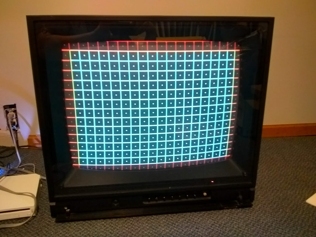
I've been pointed this way by some folks who were unsuccessful in trying to help me RGB mod my monitor. Thanks in advance for the help! I'm currently trying to convert an old "prosumer" monitor for arcade use. It's the Proton 602M, and in its day it was a very high-end monitor. I got this one from the original owner, who barely used it since the 1980s, and the tube and chassis are still in absolutely fantastic shape for their age. It apparently has been serviced for a recap at least once in its life, so it was very well cared for. This monitor also had a special power supply with drive and deflection circuits built separated from eachother, with a crazy-weirdo split flyback like nothing I've seen before. As you can see, the convergence and geometry are still pristine. Hence, why I'd love to build it into an arcade machine.
Note that this monitor has no OSD, no closed captioning, no PIP, nothing of that sort. Originally it came with composite input and TTL RGB input, and that's it. Much of the onboard logic is done with discrete transistors, but there are a handful of ICs whose datasheets I cannot seem to find because of age.
(the image below was generated with composite input)
Unfortunately I'm having issues with modding it for RGB, and I'm hoping some folks here could help or at least point me in the right direction. When I have my signals hooked up, it looks like this:

Right now I have a Neo Geo MV1C mobo hooked up to it, and the RGB signals are attenuated with 240 ohm resistors, and the sync is attenuated with a 1k resistor. I am currently inputting sync through the composite input jack, and RGB are connected to some convenient test points labeled TP-54R, G, and B. You can see them on these circuit diagrams.
Annotated Circuit Diagram.Red and Green highlights indicate RGB input test points, yellow indicates various sync injection points I tried. Note that only sync injection point 1, the composite input, had any effect at all. All other injection points seemed to produce no image at all.
Block Diagram
More circuit diagrams for daughter boards
Additional Photos: https://photos.app.goo.gl/cF9RUwfsmknwD5LK9
Note that this monitor has no OSD, no closed captioning, no PIP, nothing of that sort. Originally it came with composite input and TTL RGB input, and that's it. Much of the onboard logic is done with discrete transistors, but there are a handful of ICs whose datasheets I cannot seem to find because of age.
(the image below was generated with composite input)
Unfortunately I'm having issues with modding it for RGB, and I'm hoping some folks here could help or at least point me in the right direction. When I have my signals hooked up, it looks like this:
Right now I have a Neo Geo MV1C mobo hooked up to it, and the RGB signals are attenuated with 240 ohm resistors, and the sync is attenuated with a 1k resistor. I am currently inputting sync through the composite input jack, and RGB are connected to some convenient test points labeled TP-54R, G, and B. You can see them on these circuit diagrams.
Annotated Circuit Diagram.Red and Green highlights indicate RGB input test points, yellow indicates various sync injection points I tried. Note that only sync injection point 1, the composite input, had any effect at all. All other injection points seemed to produce no image at all.
Block Diagram
More circuit diagrams for daughter boards
Additional Photos: https://photos.app.goo.gl/cF9RUwfsmknwD5LK9