Glad it worked! I'll pick some up today then.
my wiring isn't very clean, but I think it's much cleaner than the one you showed me:p
I thought my case was a bit too big, but turns out it's going to be a very tight squeeze since I'm not housing the psu in there with it. No ntsc encoder though.
I was able to save a lot of space my having the jamma harness outside of the case with the wires through a little hole with a grommet. Almost all of my outputs are right beside the wires for the harness.
Also, right before I close it up I'm going to test EVERY connection with a multimeter. Call me paranoid, but I'm just too scared that something horrible might happen :p
I am building a supergun...
-
Gwyrgyn Blood
- Posts: 695
- Joined: Mon Mar 06, 2006 9:48 pm
I test all of my connections as I go, makes life a lot easier. I suggest you test your supergun with a cheapo PCB just in case something goes wrong. The only real dangerous thing though is probably the power connections.
The main thing I'm looking into is working more with PCBs like I did with my potentiometers. Now my question is... is it smart to start with a simple blank grid layout PCB and then use a trace pen to draw all the connections you need?
The main thing I'm looking into is working more with PCBs like I did with my potentiometers. Now my question is... is it smart to start with a simple blank grid layout PCB and then use a trace pen to draw all the connections you need?
-
KBZ
- Posts: 1257
- Joined: Sat Mar 26, 2005 4:47 am
I actually tested all my connections as I went along too :/
I'll be testing out a cheap mvs 2 slot with no cart plugged in.
I don't know much about making the traces, If you can hook up all the ports to the pcb then I bet you could get a very small and clean sg.
now, did you wire your potentiometer like in the variable resistor figure here?

I'll be testing out a cheap mvs 2 slot with no cart plugged in.
I don't know much about making the traces, If you can hook up all the ports to the pcb then I bet you could get a very small and clean sg.
now, did you wire your potentiometer like in the variable resistor figure here?
=/
-
Gwyrgyn Blood
- Posts: 695
- Joined: Mon Mar 06, 2006 9:48 pm
It's been probably 5-6 years since I last looked at any electrical diagrams so those things are totally lost on me sadly. Basically there are 3 pins on the Potentiometer... one is the input, the others are output. The Potentiometer dial controls how much of the input goes to each output... it's basically a signal splitter. Of course in this case, one output just needs to go to Ground.
I'm not sure really how specifically you have to wire the things up. The way I did... basically if look at the pins as a triangle like /\ ... the left pins I wired to ground, right pins to input, top pin to output.
But really, just test the pot with your multimeter and it should be really obvious... just tweak the dial around and you'll see how it works.
-
Gwyrgyn Blood
- Posts: 695
- Joined: Mon Mar 06, 2006 9:48 pm
Make doubly sure all of your video wires connect up properly. My video was screwed up at first but it was just the GND wire not being properly attached. If you haven't already, put one end of the multimeter in the Jamma Harness and the other on the pins of the video output to test them, as that will check the whole circuit. Also check the +5v of course, if that doesn't hit all the right pins, your TV might not accept any signal at all.
If you are concerned it might be your pots, you can just wire the signal output directly to the DB-25 and try that. Since the grid is white you only need to bother with one of the inputs to test.
Also now that I look at it the Volume Control layout is exactly how I wired up my Potentiometers.
Kind of hard to diagnose the problem without being there to test or see it though. But if you take pictures of the thing that might help.
-
Fighter17

- Banned User
- Posts: 2291
- Joined: Sun Feb 06, 2005 2:48 am
- Location: Inside a computer
- Contact:

-
ReKleSS

- Posts: 420
- Joined: Sat Sep 03, 2005 1:38 am
Not quite true. For most potentionmeter arrangements the outer two pins are at opposite ends of the resistive material and should have a constant resistance across them, regardless of the position of the wiper. The middle pin connects to the wiper and is your output value. The usual way to wire it up is to have one outer pin as input, the other opposite pin to ground, and your output from the middle.Gwyrgyn Blood wrote:Basically there are 3 pins on the Potentiometer... one is the input, the others are output. The Potentiometer dial controls how much of the input goes to each output... it's basically a signal splitter. Of course in this case, one output just needs to go to Ground.
Come to think of it, it could work as a signal splitter if you put the input to the middle pin and take your output at the end. Not the arrangement I would use, though.
弾もまたいで通る
-
iatneH

- Posts: 3202
- Joined: Tue Jan 25, 2005 11:09 pm
- Location: Vancouver, BC, Canada
Looks a lot like my latest gun so far, don't remember if I've already posted pics. But I guess "3 DB ports and a bundle of wires sticking out of a hole in a box" is a pretty standard SG formula? So, I don't know why you're having so much trouble up until now :p


PSU from a dead DVD player, not powerful enough for CPS-2 & ST-V. The small circuit board inside contains the audio attenuation circuit and power fuses.
This one did not cost me very much to build either, the PSU was taken out of the garbage, the pre-wired harness cost around $12, box around $8, and the remainder of the small electronic bits about $15 as a generous estimate. For the ultimate cheapo, combine with my $8 hacked PS1 RGB encoder to play on a S-video television, and Sega Genesis pads at $10 each. Though obviously the construction is a far cry from a $300 Sigma.
I am also planning to update that RGB encoder in coming weeks, this time actually hacksaw the IC out so I can enclose it in a much smaller pocket-sized box. Don't know if I will buy a new PS1 for it, maybe if I can get one for $10 or less.
-
KBZ
- Posts: 1257
- Joined: Sat Mar 26, 2005 4:47 am
so I think it was the dc psu. Tested with another SG and the 2 slot seems to work.
Changed psu with an AT psu and tested the 2 slot without a cart and got this message...
apparently I need to replace one of the two CXK5814 chips on the mobo.
Anyway I tried with Ibara and it boots up just fine. But there's no sound.
I had RCA L and R wired to Speaker + and RCA Ground wired to Jamma Ground.
but apparently that will only give me a bit of sound and I should have RCA Ground wired to Speaker -
Changed psu with an AT psu and tested the 2 slot without a cart and got this message...
Code: Select all
Video ram error

Address write Read

000080000 5555 FF55Anyway I tried with Ibara and it boots up just fine. But there's no sound.
I had RCA L and R wired to Speaker + and RCA Ground wired to Jamma Ground.
but apparently that will only give me a bit of sound and I should have RCA Ground wired to Speaker -
=/
-
Gwyrgyn Blood
- Posts: 695
- Joined: Mon Mar 06, 2006 9:48 pm
RCA Ground shouldn't be wired to Speaker -, the only time you need Speaker - is if you are wiring directly to speakers.Kingbuzzo wrote: Anyway I tried with Ibara and it boots up just fine. But there's no sound.
I had RCA L and R wired to Speaker + and RCA Ground wired to Jamma Ground.
but apparently that will only give me a bit of sound and I should have RCA Ground wired to Speaker -
I had a problem where I couldn't get RCA sound output when I had both RCA jacks wired from the 10/M, and I don't remember why. Try just running audio to one speaker and get that to work first, just to eliminate chances of there being some other problem.
Second, you might try turning the thing on, then unplugging and plugging the audio cable back in. For some reason my earphones (which run through a Mono RCA > 1/8" jack converter) only work when I do that. Who knows what's up with that, probably dumb earphones though.
And the most obvious thing is to make sure you've adjusted the volume pot on the PCB and made sure your TV has some volume too. :I
Also I don't remember if you put in an audio attenuation circuit or not, but you might or might not have any luck with audio using one of those with Ibara.
-
Gwyrgyn Blood
- Posts: 695
- Joined: Mon Mar 06, 2006 9:48 pm
-
KBZ
- Posts: 1257
- Joined: Sat Mar 26, 2005 4:47 am


-
iatneH
- Posts: 3202
- Joined: Tue Jan 25, 2005 11:09 pm
- Location: Vancouver, BC, Canada
-
MattC
- Posts: 13
- Joined: Fri Nov 03, 2006 8:11 am
- Location: East Prospect, PA
- Contact:
I have some old PC power supplies and I wonder what is the minimum to use a Neo Geo Mobo, I only have a one slot one? I already have an XRGB-2 and MVS setup with controllers and some spare 400watt pc ATX power supplies.Kingbuzzo wrote:
this schematic has saved my life too
http://www.gamesx.com/arcade/cheapjamma.htm
the difference between my supergun and what almost everyone else is making, is that mine has no ntsc encoder so you can use the composite, svideo, or component on your tv. I'm using an actual rgb monitor. So my supergun is probably only costing me around $30 maybe.
Good luck in your Supergun though.
-
iatneH
- Posts: 3202
- Joined: Tue Jan 25, 2005 11:09 pm
- Location: Vancouver, BC, Canada
Consolized Ibara / dedicated SH3 supergun
Hey, going to hijack your thread Kingbuzzo. Though if enough people are interested I can ask a mod to split this away...
I just finished making my standalone Ibara supergun this morning. Preparing port holes in the case took around 5 hours (I did it mostly using only a Swiss knife, and a tiny bit of Dremeling), and the wiring took me another 6 hours or so. Making superguns is tedious work!
This is a non-permanent consolized Ibara, meaning I can swap out the PCB for any other SH3 board. But due to the PCB and harness being contained inside the unit, it is basically dedicated to only SH3 games. Not that I have any other SH3 boards. But the point of this was that I still think setting up my superguns is complicated and messy, so I wanted to make something as close to plug-and-play as possible. I think I have achieved this, as the only things I need to plug in are an AC cable, A/V cables, and controllers.
Power supply and power switch are from a DVD player, same one as in my earlier post. The video encoder is a JROK v3.1 S-video/composite encoder. I have included a switch which directs the RGBS signals to only one of the internal JROK or RGB output port, so it is still possible for me to hook up to a RGB monitor or an external JROK v4.1 component encoder without any signal loss due to splitting. Controller ports are NeoGeo standard as usual.
Unlike my earlier guns, everything is securely bolted down so I can shake it around and things inside will not move, and should be quite safe for transport inside a backpack.
The entire unit measures about 30cm x 20 cm x 10 cm. So it is quite large, but given that there is practically nothing that needs to be attached externally including the PCB, I think it is alright.
I think that is all for features..... time for pictures! I sort of did take progress pictures this time.

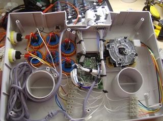
Ibara PCB fastened to the top case.

All port holes and mounting holes have been drilled out of the bottom case. Some of the circular holes still needed to be reamed larger.

The PSU, power fuse board, and JROK will be raised off the bottom and mounted on pillars.

Just trying on for size...

Almost finished wiring. The controller ports still need to be wired, but at this point I was able to do an audio/video check, and after fixing my incorrectly wired audio, I was able to continue on to the last step...
(This is the fourth supergun I have made, and I swear the audio gets me every time.)

Everything is completely wired up. Time to put the two pieces together...


Front of the unit with two NeoGeo controller ports, coin button, service & test buttons. Back of the unit has S-video/composite/audio jacks, RGB output port and RGB/NTSC switch. Also seen are the power switch and AC input socket.

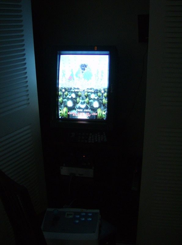
It's so easy (to set up...)!!! The game itself is so hard I want to cry...
How's that, KB? It's hard to believe you were sitting on Ibara for so long without a working supergun. I could barely wait to get this finished ASAP!
edit: got a clearer action shot :]
edit2: It does work with other boards but it's ugly.

I just finished making my standalone Ibara supergun this morning. Preparing port holes in the case took around 5 hours (I did it mostly using only a Swiss knife, and a tiny bit of Dremeling), and the wiring took me another 6 hours or so. Making superguns is tedious work!
This is a non-permanent consolized Ibara, meaning I can swap out the PCB for any other SH3 board. But due to the PCB and harness being contained inside the unit, it is basically dedicated to only SH3 games. Not that I have any other SH3 boards. But the point of this was that I still think setting up my superguns is complicated and messy, so I wanted to make something as close to plug-and-play as possible. I think I have achieved this, as the only things I need to plug in are an AC cable, A/V cables, and controllers.
Power supply and power switch are from a DVD player, same one as in my earlier post. The video encoder is a JROK v3.1 S-video/composite encoder. I have included a switch which directs the RGBS signals to only one of the internal JROK or RGB output port, so it is still possible for me to hook up to a RGB monitor or an external JROK v4.1 component encoder without any signal loss due to splitting. Controller ports are NeoGeo standard as usual.
Unlike my earlier guns, everything is securely bolted down so I can shake it around and things inside will not move, and should be quite safe for transport inside a backpack.
The entire unit measures about 30cm x 20 cm x 10 cm. So it is quite large, but given that there is practically nothing that needs to be attached externally including the PCB, I think it is alright.
I think that is all for features..... time for pictures! I sort of did take progress pictures this time.

Ibara PCB fastened to the top case.

All port holes and mounting holes have been drilled out of the bottom case. Some of the circular holes still needed to be reamed larger.

The PSU, power fuse board, and JROK will be raised off the bottom and mounted on pillars.

Just trying on for size...

Almost finished wiring. The controller ports still need to be wired, but at this point I was able to do an audio/video check, and after fixing my incorrectly wired audio, I was able to continue on to the last step...
(This is the fourth supergun I have made, and I swear the audio gets me every time.)

Everything is completely wired up. Time to put the two pieces together...


Front of the unit with two NeoGeo controller ports, coin button, service & test buttons. Back of the unit has S-video/composite/audio jacks, RGB output port and RGB/NTSC switch. Also seen are the power switch and AC input socket.

It's so easy (to set up...)!!! The game itself is so hard I want to cry...
How's that, KB? It's hard to believe you were sitting on Ibara for so long without a working supergun. I could barely wait to get this finished ASAP!
edit: got a clearer action shot :]
edit2: It does work with other boards but it's ugly.

Last edited by iatneH on Mon Feb 04, 2008 5:08 am, edited 2 times in total.
-
overkill55

- Posts: 196
- Joined: Tue Jul 10, 2007 7:13 pm
-
iatneH
- Posts: 3202
- Joined: Tue Jan 25, 2005 11:09 pm
- Location: Vancouver, BC, Canada
Thanks man, did you finally get any PCBs to use with your gun? This one is definitely nicer than the one I gave you 
The problem with compatibility here is purely physical. Electronically, I think this one should be compatible with almost any PCB, but physically it's not since the JAMMA harness is inside. I did not drill any holes through which I can pull the harness outside (and the wires are too short anyway), so the PCB has to stay inside. As far as I know, only SH3 PCBs are small enough to fit inside this box. As you can see in the first picture, the footprint of the PCB already covers a large portion of the interior.
I guess maybe I could run another PCB on it without the top cover, since the wires on the harness are just long enough for me to take the cover off without damaging anything.
I'm working on putting a more powerful power supply into my third supergun, so actually if you want my SG#1 which is also enclosed inside a metal box and fully cable-compatible with the one you have, then maybe we can work something out...
-
overkill55
- Posts: 196
- Joined: Tue Jul 10, 2007 7:13 pm
Oh ok, I see your point about the size. I may just take you up on your offer as well, shoot me a PM if you decide to.
I was thinking about making a wooden enclosure for the one I have now so that the ports can be mounted and such
I was thinking about making a wooden enclosure for the one I have now so that the ports can be mounted and such
People I have dealt with successfully: bleem (x2), spazicon, sven666, sparky, iatneH, Dragon1952, kozo, Ghegs
-
KBZ
- Posts: 1257
- Joined: Sat Mar 26, 2005 4:47 am
ok, I finally did it. Having some troubles with my camera, so I'll get some close up pictures later.
I used the same case as iatneh's ibara standalone, but sanded off the off green texture.
Using a Jrok 3.1, and an Arcade PSU. Silly me forgot to wire 2p select, -5 volt, and was too lazy to add rgb regulators but oh well. I can always fix that later.


and I finished properly wiring my modded agetec stick so i can use it with sg, adapters for ps2, ss, usb, as well as dc natively.
phew! I thought I'd never be done. Thanks for the help everyone.
I used the same case as iatneh's ibara standalone, but sanded off the off green texture.
Using a Jrok 3.1, and an Arcade PSU. Silly me forgot to wire 2p select, -5 volt, and was too lazy to add rgb regulators but oh well. I can always fix that later.
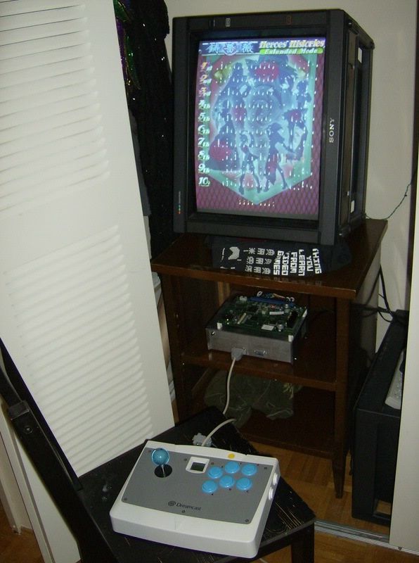
and I finished properly wiring my modded agetec stick so i can use it with sg, adapters for ps2, ss, usb, as well as dc natively.
phew! I thought I'd never be done. Thanks for the help everyone.
Last edited by KBZ on Sun Jul 27, 2008 8:27 pm, edited 1 time in total.
=/
-
iatneH
- Posts: 3202
- Joined: Tue Jan 25, 2005 11:09 pm
- Location: Vancouver, BC, Canada
Vely nice, finally! Look at the time since the last post, exactly 6 months. If you want to sell this gun, you have to charge half a year's salary, just so newbies know the work that goes into building ;) Well, it's not technically difficult work, just very tedious. I still think the worst part is just making mounting holes in the case.
Also, I got a little pushbutton with built-in LED from Lee's, I'm thinking of replacing my coin switch with it. But I'm even too lazy to ream the existing hole larger to fit the new switch -___________________-;;;
Ready for shmupmeet soon!
Also, I got a little pushbutton with built-in LED from Lee's, I'm thinking of replacing my coin switch with it. But I'm even too lazy to ream the existing hole larger to fit the new switch -___________________-;;;
Ready for shmupmeet soon!