turns out i was just an idiot and the equipment on my test bench wasn't using a combined Csync. works perfectly now.jefftherobot wrote: ↑Wed Aug 28, 2024 1:29 amYou're correct,demonpoodle wrote: ↑Tue Aug 27, 2024 8:52 pm everything is 60hz. I feel like it just has to be something simple thats being overlooked.
Am I correct in my understanding that, you set the tv to the composite input, plug the sync into the existing RCA jack for said input, then toggle the blanking pin switch to your injected RGB input to display the image? and it still reads the sync from the composite line?
or is there something else that needed to be done on the sync line that I'm missing?
What is your setup? You running a console? Have you tested it on another TV?
TV RGB mod thread
-
demonpoodle

- Posts: 5
- Joined: Fri Jun 24, 2011 4:58 pm
Re: TV RGB mod thread
You must be quick and smooth like an orange.
-
rick_z
- Posts: 1
- Joined: Thu Mar 12, 2020 2:14 pm
Re: TV RGB mod thread
Hello helloplasticbugs wrote: ↑Sun Jul 21, 2019 6:49 am I picked up a tiny 9" trinitron (Sony KV-8AD10) at my local thrift shop for $10 and would love to RGB mod it. It has the old-style green OSD text. I found the schematic and it looks like the OSD chip's RGB output pretty much goes directly into the neck board without passing through the jungle chip. I couldn't find the exact schematic for the Sanyo Jungle IC in this TV, but the chip that looks pretty much identical to the one in my set doesn't have RGB inputs.
Only the green output from the OSD/CPU chip is getting sent pretty much directly to the neckboard -- it's connected to a resistor (220 Ohm) and 47p capacitor to ground. Then it goes through a 10uh inductor coil and another 22uh inductor coil, through a transistor and then it meets up with the green video signal on the neckboard.
The green OSD signal is labeled CHR here:
It looks like the RGB output is ~4.5V TTL from the OSD chip based on the Sanyo IC's datasheet.
TV schematic is here.
Is this a lost cause for an easy mod since there's no intercepting of the OSD signal between the OSD chip and the jungle chip?
Edit: I'm going to try to source the transistors and inductors for my red and blue RGB signals to match the green signal and see if that works.


Does it worked out, was this tv set RGB mudded ?
-
Eddie-samma
- Posts: 1
- Joined: Sat Nov 09, 2024 1:59 am
Re: TV RGB mod thread
Hello, new to posting here but long time lurker. I'm attempting to determine the schematic for what I need to mux an rca colortrack plus. I have the service manual downloaded and it seems the color lines don't have inline resistors. We'll not where I had expected. It comes from the micom then through a divider then a pnp transistor and only a capcitor inline after the transistor. Any help would be greatly appreciated.
The model of the crt is 26634SF
The model of the crt is 26634SF
-
realm
- Posts: 26
- Joined: Sat Dec 04, 2021 5:01 am
Re: TV RGB mod thread
Hello everyone,
I'm currently working on an RGB MUX mod for my older JVC D-Series AV-32D800. I successfully completed the mod but ran into an issue with screen brightness when using RGB.
I wasn't able to find the service manual for my exact model but the AV-36D201 has a similar chassis. I followed the MUX mod write up for that model on Sunthar's website. My model is the AV-32D800, it has PIP but the AV-36D201 does not, everything else looks to be the same as my chassis.
The issue I'm having is with the PIP board. When it's plugged into the main board the RGB is very dim. When I remove the board the RGB brightness looks perfect. I'm assuming the PIP board adds a load to the OSD MUX circuit and my resistor values are calculated for a circuit without the boards load based on the write up I followed.
I tried swapping out the 75R terminating resistors to 150R, this improved the brightness but not significantly. I think I need to lower the RGB line resistors from 390R to something lower but I don't want to damage anything.
What would be the best solution here? Should I just remove the PIP board and have perfect RGB brightness? Or should I try a lower resistor value for the RGB lines?
Thanks
-
KPackratt2k
- Posts: 281
- Joined: Sun Apr 04, 2021 11:02 pm
- Location: Seattle, WA, USA
Re: TV RGB mod thread
I would remove the PIP board from the TV, it makes no sense to keep it installed if you don't plan on using that feature. For most TVs with a PIP feature, you have to remove the board responsible for it when RGB modding since you'll be tapping into the RGB lines that were used by the PIP board. With analog TV broadcasts no longer existing, I doubt you'll be using PIP anyway.
Store the PIP board somewhere in case you decide to revert the TV back to stock condition in the future.
Store the PIP board somewhere in case you decide to revert the TV back to stock condition in the future.
-
realm
- Posts: 26
- Joined: Sat Dec 04, 2021 5:01 am
Re: TV RGB mod thread
Hey thanks for your suggestions. I think that's what I'll do, I'm never using PIP. Another issue I just notice, the OSD does not work when using component input. I have to do some more investigation as to why, it works fine over RGB. Most likely something to do with the PIP board being removed.KPackratt2k wrote: ↑Mon Nov 11, 2024 12:34 am I would remove the PIP board from the TV, it makes no sense to keep it installed if you don't plan on using that feature. For most TVs with a PIP feature, you have to remove the board responsible for it when RGB modding since you'll be tapping into the RGB lines that were used by the PIP board. With analog TV broadcasts no longer existing, I doubt you'll be using PIP anyway.
Store the PIP board somewhere in case you decide to revert the TV back to stock condition in the future.
Spoiler
I plugged the PIP board back in and the OSD over component works fine. I think the right solution for this would be to change the RGB resistor values
-
realm
- Posts: 26
- Joined: Sat Dec 04, 2021 5:01 am
Re: TV RGB mod thread
Hello everyone,
I did some more research on other JVC RGB MUX mods and found a video on youtube for the AV-36850 which uses a similar MICOM. At first his mux circuit was based on 0.5Vpp but it was too dim so he ended up going with a circuit based on 1Vpp and that solved the issue.
My stock OSD inline resistors are 2.2k with 330R stock grounding resistors. My current MUX circuit is based on 0.7Vpp with diodes and it's too dim so I think it needs a circuit based on 1Vpp but I'm running into a problem. I can't find a MUX resistor calculation table for 1Vpp. I can only find 0.7Vpp and 0.5Vpp. Is there anyone that can help me calculate the resistor values for a 1Vpp MUX circuit?
Thanks
-
patricksouza472
- Posts: 7
- Joined: Fri Sep 03, 2021 3:55 am
Re: TV RGB mod thread
Hey thanks! It's a Brazilian set by CCE, model HPS-1471, but it's based on a Chinese chassis called 34BI. It even had the cutout for a SCART socket and pins on the board even though we never had any SCART equipment here lolledoeye wrote: ↑Tue Oct 29, 2024 2:21 amMan that looks amazing! Good work! What is the model of the CRT?patricksouza472 wrote: ↑Mon Oct 14, 2024 7:09 pm Just finished my first successful RGB mod after failing with an LG
I had to change some jumpers, add 75ohm resistors (which I've salvaged from a dead CRT monitor) and enable RGB input on service menu. It uses a TDA9570H controller, which has unused RGB pins. 22nf caps on RGB pins (from factory). I'm quite happy with how it turned out, even though the picture quality isn't perfect, it's waaaay better than composite.
Shoutout to @tongshadow who first posted about a mod using the TDA9570H, he helped me during the process

-
VEGETA

- Posts: 486
- Joined: Mon May 31, 2021 10:40 am
Re: TV RGB mod thread
Hello,
I have SW-292M80 sony trinitron and it has component inputs that i am happy with. however, searching around i found that it has jungle chip which has rgb inputs of some sort.
here is the manual i found: https://filebin.net/1qmyjsa4j35dzpqw/so ... er.2.0.pdf
can i RGB mod this thing? how?
here are some pics from it: https://slow.pics/c/0RyivpcL
-
syboxez
- Posts: 99
- Joined: Sun Jul 24, 2016 4:33 am
Re: TV RGB mod thread
I just RGB mux modded my Toshiba CF19F22 (info, including service manual here), and I was attempting to slightly adjust VHold so that it can accept 50Hz signals; color doesn't matter since it's an RGB signal. Right now, it can accept ~53Hz-74Hz without rolling.
I can't find any way to adjust VHold in the CRT, and I was wondering if it is possible or if that circuitry is embedded inside the jungle ic.
I can't find any way to adjust VHold in the CRT, and I was wondering if it is possible or if that circuitry is embedded inside the jungle ic.
-
toastyev
- Posts: 1
- Joined: Wed Dec 11, 2024 2:23 am
Re: TV RGB mod thread
I have a weird issue with a component mod on my Magnavox 14MS2331. Everything works great except the green cutoff is aggressive only over component making many dark greys appear green. Colors are perfectly balanced over composite. Additionally white levels look great, it is just for dark colors where I have issue. There are no rgb cutoff settings in service menu, only white levels so I cannot compensate there. I used 0.1uF as detailed by others. Could there be issues with tolerance of coupling capacitors? Any ideas to get the green cutoff in line with the others over component? This has been very frustrating as everything looks great otherwise.
-
krimstah
- Posts: 20
- Joined: Fri Dec 28, 2018 8:51 am
Re: TV RGB mod thread
Hi Everyone,
I have a TEAC DVTV5190F is it possible to RGB mod this?
User Manual: https://archive.org/details/manualsbase ... 7/mode/2up
Service Manual: https://www.manualslib.com/manual/27562 ... -DVTV5190F
Picture of unit:
https://imgur.com/a/aRz8Scq#6cQjQ9S
I have a TEAC DVTV5190F is it possible to RGB mod this?
User Manual: https://archive.org/details/manualsbase ... 7/mode/2up
Service Manual: https://www.manualslib.com/manual/27562 ... -DVTV5190F
Picture of unit:
https://imgur.com/a/aRz8Scq#6cQjQ9S
-
Pikkon

- Posts: 129
- Joined: Tue May 26, 2015 6:25 am
- Location: Florida
Re: TV RGB mod thread
I had a similar problem,don't have the tv anymore but I think I added a resister to try and lower the green,you could try a pot and see how it looks.toastyev wrote: ↑Wed Dec 11, 2024 3:22 am I have a weird issue with a component mod on my Magnavox 14MS2331. Everything works great except the green cutoff is aggressive only over component making many dark greys appear green. Colors are perfectly balanced over composite. Additionally white levels look great, it is just for dark colors where I have issue. There are no rgb cutoff settings in service menu, only white levels so I cannot compensate there. I used 0.1uF as detailed by others. Could there be issues with tolerance of coupling capacitors? Any ideas to get the green cutoff in line with the others over component? This has been very frustrating as everything looks great otherwise.
Last edited by Pikkon on Mon Jan 06, 2025 12:53 am, edited 1 time in total.
-
B3AR_creative
- Posts: 3
- Joined: Sun Jan 05, 2025 4:47 pm
Re: TV RGB mod thread
Why Hello there.
I was wondering if you fine folk might be able to help me along my journey to mod a set that I'm hoping didn't cost me £60 to be a lost cause. It's pretty old, its an ITT Trimline CT2512 and only has an RF input. I've done my due diligence and managed to get hold of the schematics and I believe it does have a PAL Decoder Chip TDA3561. I'd really appreciate a bit of guidance as to next steps, if all just to give me a bit more confidence attempting it. I have gone through some sunthar, 8bit guy and MacroRetros tutorials but I'm getting lost in specifics for this set.


Thank you!
I was wondering if you fine folk might be able to help me along my journey to mod a set that I'm hoping didn't cost me £60 to be a lost cause. It's pretty old, its an ITT Trimline CT2512 and only has an RF input. I've done my due diligence and managed to get hold of the schematics and I believe it does have a PAL Decoder Chip TDA3561. I'd really appreciate a bit of guidance as to next steps, if all just to give me a bit more confidence attempting it. I have gone through some sunthar, 8bit guy and MacroRetros tutorials but I'm getting lost in specifics for this set.
Thank you!
-
vol.2

- Posts: 3292
- Joined: Mon Oct 31, 2016 3:13 pm
- Location: bmore
Re: TV RGB mod thread
Yes, it looks promising. From the datasheet:B3AR_creative wrote: ↑Sun Jan 05, 2025 5:16 pm Why Hello there.
I was wondering if you fine folk might be able to help me along my journey to mod a set that I'm hoping didn't cost me £60 to be a lost cause. It's pretty old, its an ITT Trimline CT2512 and only has an RF input. I've done my due diligence and managed to get hold of the schematics and I believe it does have a PAL Decoder Chip TDA3561. I'd really appreciate a bit of guidance as to next steps, if all just to give me a bit more confidence attempting it. I have gone through some sunthar, 8bit guy and MacroRetros tutorials but I'm getting lost in specifics for this set.
"13, 15, 17. Inputs for external RGB signalsThe external signals must be a.c.-coupled to the inputs viaa coupling capacitor of about 100 nF. Source impedanceshould not exceed 150Ω. The input signal required fora 5 V peak-to-peak output signal is 1 V peak-to-peak.At the RGB outputs the black level of the inserted signal isidentical to that of normal RGB signals. When these inputsare not used the coupling capacitors have to be connectedto the negative supply."
So one would assume that it would just take inserting the RGB signal into those pins with an series 100nf ceramic capacitor, and probable a 75ohm resistor to ground for termination.
The IC is from 1982, so I would doubt there is any concern about an EEPROM to set the input. My first attempt would probably just to do what the datasheet for the jungle IC says and see what happens. You will need to feed it composite sync or composite video as sync through the luminance input signal most likely, so in order to do that you need to look at the schematic and figure out where exactly the output of the IF section of the RF input is.
You need to do it this way because there are various sections of the circuit like the contrast and possibly automatic brightness or whatever that also need the sync signal to work, so you can't just bypass all that junk and stick luma into the jungle IC. There will be a point somewhere in the circuit that the whole RF circuit outputs luma and that will get split off to everything else. You need to cut the circuit off at that point and wire you composite video directly into the circuit, effectively removing the RF from the story
If you wanted to keep the RF, you'd have to mux it with a small circuit or put it on a switch.
It looks like the Luma comes in from the RF/IF section on that thick black line that says "Composite Colour Signal" and is then broken off for sync purposes, etc.
There appears to be a pin to select the external RGB input pins. Pin 9.
"9. Video-data switchingThe insertion circuit is activated by means of this input byan input pulse between 1 V and 2 V. In that condition, theinternal RGB signals are switched off and the insertedsignals are supplied to the output amplifiers. If only normaloperation is wanted this pin should be connected to thenegative supply. The switching times are very short(< 20 ns) to avoid coloured edges of the inserted signalson the screen"
-
krimstah
- Posts: 20
- Joined: Fri Dec 28, 2018 8:51 am
Re: TV RGB mod thread
Can anyone assist please?
krimstah wrote: ↑Sat Jan 04, 2025 9:39 pm Hi Everyone,
I have a TEAC DVTV5190F is it possible to RGB mod this?
User Manual: https://archive.org/details/manualsbase ... 7/mode/2up
Service Manual: https://www.manualslib.com/manual/27562 ... -DVTV5190F
Picture of unit:
https://imgur.com/a/aRz8Scq#6cQjQ9S
-
vol.2
- Posts: 3292
- Joined: Mon Oct 31, 2016 3:13 pm
- Location: bmore
Re: TV RGB mod thread
There is no full datasheet for the Jungle IC available online that I can find, just a block diagram from the TV. The Jungle IC has RGB inputs on Pins 46, 47 and 48, but it's not clear to me how sync is input in that case. There's an option in the service menu to turn on RGB mode in the IC, but without a full datasheet for the Jungle IC, I wouldn't know exactly how to wire it up. Typically there are three things you need to do at minimum to get RGB runningkrimstah wrote: ↑Wed Jan 08, 2025 8:36 am Can anyone assist please?
krimstah wrote: ↑Sat Jan 04, 2025 9:39 pm Hi Everyone,
I have a TEAC DVTV5190F is it possible to RGB mod this?
User Manual: https://archive.org/details/manualsbase ... 7/mode/2up
Service Manual: https://www.manualslib.com/manual/27562 ... -DVTV5190F
Picture of unit:
https://imgur.com/a/aRz8Scq#6cQjQ9S
1) place to insert RGB (okay done)
2)place to insert sync (not sure)
3) place to turn on RGB (not sure)
The sync might be muxed with one of the colors, or it might need to be passed through the composite signal path of the tv in order to feed the deflection pulses. It's also not clear to me what the voltage levels should be for the Jungle IC because no datasheet.
The way to turn it on could be the service menu, but you might also need to set a blanking pin somewhere. Or it's possible that the service menu is simply pulling the blanking pin high or low. Again, it's not clear what needs to be done.
To make matters more complicated, it's got an integrated DVD player, which will be fed to the jungle IC through composite or YUV, and that may be conflicting with any mods you want to do.
I would leave it alone. There's too big a risk you will brick it.
-
krimstah
- Posts: 20
- Joined: Fri Dec 28, 2018 8:51 am
Re: TV RGB mod thread
Thanks Mate ,
I have a picture of the chip if you know what it is, if you think it is still a no go I will follow your advice
https://imgur.com/a/OaT3Mli
I have a picture of the chip if you know what it is, if you think it is still a no go I will follow your advice
https://imgur.com/a/OaT3Mli
vol.2 wrote: ↑Wed Jan 08, 2025 3:53 pmThere is no full datasheet for the Jungle IC available online that I can find, just a block diagram from the TV. The Jungle IC has RGB inputs on Pins 46, 47 and 48, but it's not clear to me how sync is input in that case. There's an option in the service menu to turn on RGB mode in the IC, but without a full datasheet for the Jungle IC, I wouldn't know exactly how to wire it up. Typically there are three things you need to do at minimum to get RGB runningkrimstah wrote: ↑Wed Jan 08, 2025 8:36 am Can anyone assist please?
krimstah wrote: ↑Sat Jan 04, 2025 9:39 pm Hi Everyone,
I have a TEAC DVTV5190F is it possible to RGB mod this?
User Manual: https://archive.org/details/manualsbase ... 7/mode/2up
Service Manual: https://www.manualslib.com/manual/27562 ... -DVTV5190F
Picture of unit:
https://imgur.com/a/aRz8Scq#6cQjQ9S
1) place to insert RGB (okay done)
2)place to insert sync (not sure)
3) place to turn on RGB (not sure)
The sync might be muxed with one of the colors, or it might need to be passed through the composite signal path of the tv in order to feed the deflection pulses. It's also not clear to me what the voltage levels should be for the Jungle IC because no datasheet.
The way to turn it on could be the service menu, but you might also need to set a blanking pin somewhere. Or it's possible that the service menu is simply pulling the blanking pin high or low. Again, it's not clear what needs to be done.
To make matters more complicated, it's got an integrated DVD player, which will be fed to the jungle IC through composite or YUV, and that may be conflicting with any mods you want to do.
I would leave it alone. There's too big a risk you will brick it.
Last edited by krimstah on Thu Jan 09, 2025 8:41 am, edited 1 time in total.
-
vol.2
- Posts: 3292
- Joined: Mon Oct 31, 2016 3:13 pm
- Location: bmore
Re: TV RGB mod thread
Sorry, the picture doesn't really help at all. I can find a short form datasheet with the pinout, and they show the pins relevant to the application in the set's service manual, but what I would need to comfortably tell you it can be done is the full datasheet for the jungle IC. That would give the information that is necessary about how to enable the RGB and provide a path to modifying your existing circuit. The fact that it's also a DVD combo unit makes things especially difficult as there are some internal connections between the DVD portion and the TV portion that would need to be accounted for.krimstah wrote: ↑Thu Jan 09, 2025 8:40 am Thanks Mate ,
I have a picture of the chip if you know what it is, if you think it is still a no go I will follow your advice
https://imgur.com/a/OaT3Mli
The service manual does give op codes in the EEPROM for turning on the RGB (and Component Video), but because your specific set doesn't have that function by default, doing so without populating the rest of the circuit correctly first could very likely result in a black screen that you couldn't recover from without flashing a new EEPROM and swapping it out; not a trivial operation.
The problem with doing stuff like this on later sets is that they accomplished a lot of these functions electronically rather with switches or fixed voltages on pins. In older sets, inputs were selected by either flipping a physical switch or (permanently) by way of applying a specific voltage (or ground reference) to a specific pin on an IC. Once this process became automated, complex switching ICs were used to control these things so that higher end models could accomplish switching in user menus. That functionality is provided by storing the matrix of settings in non-volatile memory, which typically communicates with the jungle IC to facilitate switching. In a set that doesn't come with an input, they turn all that stuff off at the factory and flash the memory that way. Sometimes (not always) all of the functions that ever might be used for a whole range of TVs are included in every instance of the flashed ROM, regardless if those functions are available in the particular set or not. Your user manual specifically says which options can be changed and which shouldn't be changed. RGB and Component are in the "don't change" settings list.
-
MarkOZLAD
- Posts: 1040
- Joined: Thu May 18, 2017 12:39 pm
Re: TV RGB mod thread
In my experience when these sets have their INSS.W2 (BL) hard wired to 8V they are locked into Component mode.krimstah wrote: ↑Sat Jan 04, 2025 9:39 pm Hi Everyone,
I have a TEAC DVTV5190F is it possible to RGB mod this?
User Manual: https://archive.org/details/manualsbase ... 7/mode/2up
Service Manual: https://www.manualslib.com/manual/27562 ... -DVTV5190F
Picture of unit:
https://imgur.com/a/aRz8Scq#6cQjQ9S
I can't be sure of this, the set's service menu options in the manual show both Component and RGB settings enabled - quite confusing.
I'd be surprised if you can mod this set for RGB but I cannot rule it out.
___________________________________________________
MarkOZLAD
OSD/External RGB Mux Diagram
OSD/External RGB Mux Resistor Value Table 0.7Vp-p : 0.5Vp-p
"Imagine toggle switch OSD modding a TV in 2019" - maxtherabbit
MarkOZLAD
OSD/External RGB Mux Diagram
OSD/External RGB Mux Resistor Value Table 0.7Vp-p : 0.5Vp-p
"Imagine toggle switch OSD modding a TV in 2019" - maxtherabbit
-
krimstah
- Posts: 20
- Joined: Fri Dec 28, 2018 8:51 am
Re: TV RGB mod thread
Hi Mark and Vol2
I have found the Datasheet , If that still does not help I will leave the set intact.
https://pdfupload.io/docs/0e8be18b
Thanks
I have found the Datasheet , If that still does not help I will leave the set intact.
https://pdfupload.io/docs/0e8be18b
Thanks
MarkOZLAD wrote: ↑Thu Jan 09, 2025 11:11 pmIn my experience when these sets have their INSS.W2 (BL) hard wired to 8V they are locked into Component mode.krimstah wrote: ↑Sat Jan 04, 2025 9:39 pm Hi Everyone,
I have a TEAC DVTV5190F is it possible to RGB mod this?
User Manual: https://archive.org/details/manualsbase ... 7/mode/2up
Service Manual: https://www.manualslib.com/manual/27562 ... -DVTV5190F
Picture of unit:
https://imgur.com/a/aRz8Scq#6cQjQ9S
I can't be sure of this, the set's service menu options in the manual show both Component and RGB settings enabled - quite confusing.
I'd be surprised if you can mod this set for RGB but I cannot rule it out.
-
vol.2
- Posts: 3292
- Joined: Mon Oct 31, 2016 3:13 pm
- Location: bmore
Re: TV RGB mod thread
Wrong IC. That's the closed captioning chip that is used to decode and overlay text on the screen for people that have hearing impairment. The video IC is TDA9370PS/N2. There is a short form sheet out there I can find for it, but it only has the pinout and not the information on how it works. We would need the real full datasheet.krimstah wrote: ↑Fri Jan 10, 2025 9:25 am Hi Mark and Vol2
I have found the Datasheet , If that still does not help I will leave the set intact.
https://pdfupload.io/docs/0e8be18b
Thanks
-
Bard_the_Bowman
- Posts: 52
- Joined: Mon Apr 29, 2024 5:42 am
Re: TV RGB mod thread
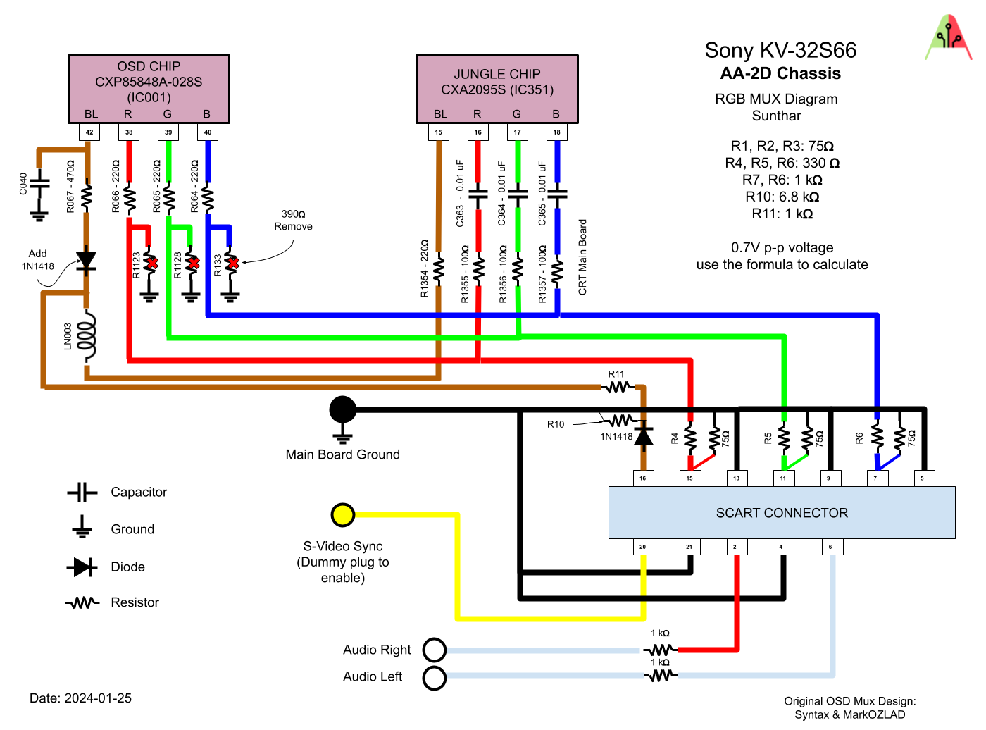
I just did an RGB and component mod to a Sony AA-2D set (KV35s42) and I'm getting this weird horizontal blurring of the OSD text. Does anyone know what could be causing it?
https://imgur.com/gallery/BtUGtgj
https://imgur.com/gallery/BtUGtgj
-
vol.2
- Posts: 3292
- Joined: Mon Oct 31, 2016 3:13 pm
- Location: bmore
Re: TV RGB mod thread
Assuming it for sure wasn't there before you did the mod, please post all the details of what you changed by way of a schematic with red lines tracing the changes, annotated with an explanation.Bard_the_Bowman wrote: ↑Sat Jan 11, 2025 9:05 pm I just did an RGB and component mod to a Sony AA-2D set (KV35s42) and I'm getting this weird horizontal blurring of the OSD text. Does anyone know what could be causing it?
https://imgur.com/gallery/BtUGtgj
It's obviously a product of whatever you did, so the only way for anyone to know is to help you retrace your steps and figure out what caused it.
Might be something like added (or altered) capacitance effecting the frequency response characteristics of the OSD video information.
-
Bard_the_Bowman
- Posts: 52
- Joined: Mon Apr 29, 2024 5:42 am
Re: TV RGB mod thread
Thanks. Turns out I was just being silly, I have the mux board installed on the case of the TV with a quick-connect cable to the board and I didn't have the mux board connected when I took the picture. Menu looks fine now that it's hooked up.vol.2 wrote: ↑Sun Jan 12, 2025 2:54 amAssuming it for sure wasn't there before you did the mod, please post all the details of what you changed by way of a schematic with red lines tracing the changes, annotated with an explanation.Bard_the_Bowman wrote: ↑Sat Jan 11, 2025 9:05 pm I just did an RGB and component mod to a Sony AA-2D set (KV35s42) and I'm getting this weird horizontal blurring of the OSD text. Does anyone know what could be causing it?
https://imgur.com/gallery/BtUGtgj
It's obviously a product of whatever you did, so the only way for anyone to know is to help you retrace your steps and figure out what caused it.
Might be something like added (or altered) capacitance effecting the frequency response characteristics of the OSD video information.
-
Bard_the_Bowman
- Posts: 52
- Joined: Mon Apr 29, 2024 5:42 am
Re: TV RGB mod thread
So now I have another problem. Everything is working, but the RGB input has terribly blown higlights. And I say highlights, as opposed to just too bright period, because the image overall is fine, but colors that are close to white, just become white, and bright scenes are completely washed out.
I used Sunthar's schematics here: https://sector.sunthar.com/assets/sony- ... qRBKNm.png
Checked and doublechecked everything. Basically identical to the diagram linked except I'm using BNC instead of SCART.
Is this something I can adjust with resistors or could it be I have something messed up in the service menu?
-
vol.2
- Posts: 3292
- Joined: Mon Oct 31, 2016 3:13 pm
- Location: bmore
Re: TV RGB mod thread
It's possible. What exactly did you change in the service menu?Bard_the_Bowman wrote: ↑Mon Jan 13, 2025 6:55 am Is this something I can adjust with resistors or could it be I have something messed up in the service menu?
-
Bard_the_Bowman
- Posts: 52
- Joined: Mon Apr 29, 2024 5:42 am
Re: TV RGB mod thread
Did some research and I’m 90% sure it’s an incorrect cable hooked up to my NTSC SNES. Evidently using a cable designed for PAL SNES will result in the blown whites I described. PAL SNES needs resistors to ground and NTSC uses coupling caps. Cable I bought on Amazon didn’t specify which it was and I’ll bet money when I take it apart tonight I’ll find it has resistors (or is just poorly made with a straight-through connection). If that’s the case I’ll just convert it and add capsvol.2 wrote: ↑Mon Jan 13, 2025 2:16 pmIt's possible. What exactly did you change in the service menu?Bard_the_Bowman wrote: ↑Mon Jan 13, 2025 6:55 am Is this something I can adjust with resistors or could it be I have something messed up in the service menu?
Last edited by Bard_the_Bowman on Mon Jan 13, 2025 6:23 pm, edited 1 time in total.
-
vol.2
- Posts: 3292
- Joined: Mon Oct 31, 2016 3:13 pm
- Location: bmore
Re: TV RGB mod thread
Crappy cables are a killer. I try to roll my own when possible.Bard_the_Bowman wrote: ↑Mon Jan 13, 2025 3:35 pmDid some research and I’m 90% sure it’s an incorrect cable hooked up to my SNES. Evidently using a cable designed for PAL snes will result in the blown whites I described. PAL SNES needs resistors to ground and NTSC uses coupling caps. Cable I bought on Amazon didn’t specify which it was and I’ll bet money when I take it apart tonight I’ll find it has resistors (or is just poorly made with a straight-through connection). If that’s the case I’ll just convert it and add capsvol.2 wrote: ↑Mon Jan 13, 2025 2:16 pmIt's possible. What exactly did you change in the service menu?Bard_the_Bowman wrote: ↑Mon Jan 13, 2025 6:55 am Is this something I can adjust with resistors or could it be I have something messed up in the service menu?
-
Bard_the_Bowman
- Posts: 52
- Joined: Mon Apr 29, 2024 5:42 am
Re: TV RGB mod thread
Oddly enough it's actually a pretty well-made cable. It's just that the listing was terribly vague/inaccurate about what specific systems it works with, and I'm pretty sure I'm going to have to modify it. I'll probably leave a negative review just based on the terrible description.vol.2 wrote: ↑Mon Jan 13, 2025 3:57 pmCrappy cables are a killer. I try to roll my own when possible.Bard_the_Bowman wrote: ↑Mon Jan 13, 2025 3:35 pmDid some research and I’m 90% sure it’s an incorrect cable hooked up to my SNES. Evidently using a cable designed for PAL snes will result in the blown whites I described. PAL SNES needs resistors to ground and NTSC uses coupling caps. Cable I bought on Amazon didn’t specify which it was and I’ll bet money when I take it apart tonight I’ll find it has resistors (or is just poorly made with a straight-through connection). If that’s the case I’ll just convert it and add caps
https://www.amazon.com/gp/product/B0C9P ... UTF8&psc=1 The cable, for anyone wondering.