TV RGB mod thread

The place for all discussion on gaming hardware
titan91
Posts: 96
Joined: Sun May 14, 2023 1:44 pm

Re: TV RGB mod thread

Post by titan91 »

Doing some initial recon on the Sony KV-20FS12. I opened it up, picture was a bit washed/bloomed out at first until I realized the funeral home I resurrected this from had the picture/contrast all the way up and brightness was high as well. After adjusting those I checked to confirm the focus was optimal from the factory (surprisingly).

This one has a small amount of dust on the CRT and chassis board, not obvious until you touch it. Picture is awesome. I'm guessing it only has a few hundred hours on it. The only signs of heat are from a single resistor on the neck board.
Spoiler
Image
Image
Image
Image
Image
I got some photos of the B board:
Spoiler
Image
Image
And the back of the A board:
Spoiler
Image
User avatar
vol.2
Posts: 2992
Joined: Mon Oct 31, 2016 3:13 pm
Location: bmore

Re: TV RGB mod thread

Post by vol.2 »

spikespiegel wrote: Sun Sep 08, 2024 1:39 am I spent many hours altering the values in the CHK1 options and had no luck at all. On the other hand, I did manage to get in the memory menu, but I have no idea what to change there and I don't dare to do that without any documentation. So, from this information, can you shed me a light? I really wanted to see this TV rgb modded, its image is fantastic.
No, I can't offer a way to "make it work." It's totally possible that it's not doable without both doing some hardware modifications around the IC and setting something in the memory. Sometimes setting a particular mode could necessitate pulling a pin on an IC up or down (or more than one pin) or something like that. Without the all the datasheets, I'm flying just as blind as you are. Even then, I probably wouldn't mess with it unless I was really sure I could do it without doing any EEPROM programming or anything like that, and there would have to be clear and obvious remarks about enabling RGB.
spikespiegel
Posts: 96
Joined: Wed Jun 16, 2021 12:52 am
Location: Mars

Re: TV RGB mod thread

Post by spikespiegel »

vol.2 wrote: Sun Sep 08, 2024 3:23 am
spikespiegel wrote: Sun Sep 08, 2024 1:39 am I spent many hours altering the values in the CHK1 options and had no luck at all. On the other hand, I did manage to get in the memory menu, but I have no idea what to change there and I don't dare to do that without any documentation. So, from this information, can you shed me a light? I really wanted to see this TV rgb modded, its image is fantastic.
No, I can't offer a way to "make it work." It's totally possible that it's not doable without both doing some hardware modifications around the IC and setting something in the memory. Sometimes setting a particular mode could necessitate pulling a pin on an IC up or down (or more than one pin) or something like that. Without the all the datasheets, I'm flying just as blind as you are. Even then, I probably wouldn't mess with it unless I was really sure I could do it without doing any EEPROM programming or anything like that, and there would have to be clear and obvious remarks about enabling RGB.

From the datasheet of the TDA935X/6X/8X PS/N2 series - TV signal processor-Teletext - decoder with embedded m-Controller:
58. The input of the vertical guard function can be connected to the black current measuring input (BLKIN) or to the beam
current limiting input (BCLIN). The switching between these modes is realised by means of the IVG bit in subaddress
2BH. When the black current input is chosen it should be noted that for a reliable operation of the protection system
and the black current stabilization system the end of the protection pulse during normal operation should not overlap
the measuring pulses (see also Fig.44). Therefore this pulse must end before line 14.
From another member with the same problem:
fandangos wrote:So I found this datasheet of the TDA9552H and it's identical to the tda9592h/n3/3/1502 pinout.

There's no publicly available datasheet for the tda9592h/n3/3/1502 that my panasonic has.

http://www.datasheetspdf.com/PDF/TDA9552H/870544/8

I'm starting to think that the TV when receiving 5+ volts to Pin 50 INSSW2, changes from YUV to composite because of a EEPROM bit somewhere.
I can enter the Service Menu and direct write values to the EEPROM.

The datasheet claims:
• A linear RGB/YUV/YPBPR input with fast blanking for
external RGB/YUV sources. The synchronisation circuit
can be connected to the incoming Y signal.

And:
RGB output circuit and black-current stabilization
In the RGB control circuit the signal is controlled on
contrast, brightness and saturation. The ICs have a linear
input for external RGB/YUV signals. Switching between
RGB and the YUV/YPRPB mode can be realised via the
YUV0/YUV1 bits in subaddress 2BH.

This means HEX address 02B which in my TV is 0 0.
That makes sense because the Jungle IC outputs RGB (at 2V).

I need to change it on the input side.


The thing is, is there any way to find out what BIT should I change to enable RGB instead of YUV?
There's a table that says:
Table 94 Enable vertical guard (RGB blanking) 0 and 1, inactive and active.

The Panasonic MS_TC-29FJ30L datahseet has all the values of the EEPROM but no indication of what they are for.

Please, any ideas?
And the Reply from MarkOzLad:
I've had a bit of a go at understanding the I2C communication in the TVs.

One thing I discovered that the addresses listed in the datasheets for the configuration bits do not directly relate to the EEPROM maps. Instead I believe you need to put an I2C device onto the TVs I2C bus and send I2C read and write commands to the chips using the addresses supplied (8A for write, 8B for read).

I haven't successfully managed to do this yet though I haven't spent a lot of time on it either. I was able to get a response from the TV but wasn't able to achieve anything constructive.
Is this info useful?
User avatar
vol.2
Posts: 2992
Joined: Mon Oct 31, 2016 3:13 pm
Location: bmore

Re: TV RGB mod thread

Post by vol.2 »

spikespiegel wrote: Sun Sep 08, 2024 4:16 am Is this info useful?
Only in that I don't have enough I2C experience to be of use. I've done some very basic I2C stuff for extremely specific hardware where I had instructions on what to do.

You might have some luck throwing all the information into an AI chat and see what the trash bots come up with. As it is, I'm a dead end on this one. MarkOzLad is already more knowledgeable than I in this.
spikespiegel
Posts: 96
Joined: Wed Jun 16, 2021 12:52 am
Location: Mars

Re: TV RGB mod thread

Post by spikespiegel »

vol.2 wrote: Sun Sep 08, 2024 4:54 pm
spikespiegel wrote: Sun Sep 08, 2024 4:16 am Is this info useful?
Only in that I don't have enough I2C experience to be of use. I've done some very basic I2C stuff for extremely specific hardware where I had instructions on what to do.

You might have some luck throwing all the information into an AI chat and see what the trash bots come up with. As it is, I'm a dead end on this one. MarkOzLad is already more knowledgeable than I in this.
@MarkOZLAD Can you give me a hand here please?
User avatar
Pikkon
Posts: 128
Joined: Tue May 26, 2015 6:25 am
Location: Florida

Re: TV RGB mod thread

Post by Pikkon »

spikespiegel wrote: Sun Sep 08, 2024 1:35 am
Pikkon wrote: Mon Jul 08, 2024 9:41 pm
spikespiegel wrote: Thu Jul 04, 2024 1:57 am I've rgb moded a Panasonic CRT TV, model TC-14A12, but I don't seem to be able to activate the blanking line.
That jungle IC look very similar to a Phillips I used to have,the chip is either Component or RGB and can't be changed in the service menu.

I did mod mine for component as that what it was set for but I had to enable it in the service menu.
Which circuit did you use to mod it to component video?
Just a standard circuit that uses 75ohm termination resisters and .1uf caps.
User avatar
gmipf
Posts: 25
Joined: Mon Jul 21, 2014 7:16 pm
Location: Germany

Re: TV RGB mod thread

Post by gmipf »

I wanted to ask whether my CRT is compatible for an RGB mod. The model is Sony KV-1435M3. I got it in Turkey. The TV has no inputs at all, besides RF. The "TV/Video" button on the remote doesn't switch the input.

Here are my photos: https://imgur.com/a/6AE8ze3

The service manual https://elektrotanya.com/sony_trinitron ... nload.html

IC001 on the service manual seem to have pins for RGB, the green line is used for the OSD. B and R is empty.

I wanted to use the RGB mux board gerbers by Sunthar, is that a good choice? Do I have any hope?

EDIT: Have found a higher quality scan of the circuit diagram, seems to be related with my model: https://i.imgur.com/YnJgZ5z.jpeg

There is another chip called Y.C-JUNGLE (IC301) with RGB pins.
alimadhi
Posts: 30
Joined: Sun Jan 26, 2014 12:53 pm

Re: TV RGB mod thread

Post by alimadhi »

Is this possible to mod to rgb

edit:
Image

Image
M61266
Image

M37160M8H
Image
Last edited by alimadhi on Wed Sep 11, 2024 7:31 pm, edited 1 time in total.
KPackratt2k
Posts: 266
Joined: Sun Apr 04, 2021 11:02 pm
Location: Seattle, WA, USA

Re: TV RGB mod thread

Post by KPackratt2k »

gmipf wrote: Mon Sep 09, 2024 7:09 pm I wanted to ask whether my CRT is compatible for an RGB mod. The model is Sony KV-1435M3. I got it in Turkey. The TV has no inputs at all, besides RF. The "TV/Video" button on the remote doesn't switch the input.

Here are my photos: https://imgur.com/a/6AE8ze3

The service manual https://elektrotanya.com/sony_trinitron ... nload.html

IC001 on the service manual seem to have pins for RGB, the green line is used for the OSD. B and R is empty.

I wanted to use the RGB mux board gerbers by Sunthar, is that a good choice? Do I have any hope?

EDIT: Have found a higher quality scan of the circuit diagram, seems to be related with my model: https://i.imgur.com/YnJgZ5z.jpeg

There is another chip called Y.C-JUNGLE (IC301) with RGB pins.
This set uses the CXA1213BS jungle chip which has no RGB inputs, therefore this set cannot be RGB modded without resorting to using an amplifier to run your RGB signals to the neckboard, which is a pretty difficult mod. It should be possible to mod it for Composite and S-Video as there are guides for adding those inputs to other sets with the same jungle chip.

viewtopic.php?t=65583
alimadhi wrote: Tue Sep 10, 2024 4:30 pm Is this possible to mod to rgb


https://iili.io/dUnrlZF.jpg
M61266
https://iili.io/dUnr1Cg.jpg

M37160M8H
https://iili.io/dUnrcj1.jpg
It depends, it looks like this set uses one of those jungle chips that can accept either 3-bit Digital RGB or Analog RGB depending on the setting on the microcontroller's code, so the chances of being able to modify it are 50/50. If you could provide the manufacturer and model number of this TV, we could search for a service manual to look at its RGB circuitry to verify if it can be modded.
bclark219
Posts: 3
Joined: Mon Sep 02, 2024 9:03 pm
Location: USA

Re: TV RGB mod thread

Post by bclark219 »

I trying to figure out the issues with this RCA F25442 I'm trying to RGB mod.
Jungle chip: SANYO LA7612A

I wired up a scart connector to my PS2 and have it running into a breadboard where I can adjust trimmer pots to adjust the RGB voltage. I got a picture on the screen but there is a weird shadow smear ghost effect to the right side of objects on the screen.
I tried disconnecting the OSD completely and it improved it slightly, I think. I tried adding diodes in line from the OSD and blanking lines and it turned the whole OSD red. It did not help the problem at either.

I'm also having trouble getting audio from the left speaker. I figured out sound only comes out the right speaker when I plug in an RCA jack (not connected to anything) in the front R audio IN. Plugging in the L audio IN messes up the picture on the screen and makes a loud buzzing noise.
Audio L+R in composite mode still works. I noticed the screen gets slightly brighter when you connect the audio jacks.

Image
Smeary shadow ghost effect next to objects.

Image
What happens when I plug in the left audio jack. It is not connected the anything. The right audio jack needs to be plugged in for sound to come out for some reason.

https://photos.app.goo.gl/9US4ypcBZvqpvd5TA

More Pictures \/
Spoiler
Image
Image
Image
Image
Image
User avatar
gmipf
Posts: 25
Joined: Mon Jul 21, 2014 7:16 pm
Location: Germany

Re: TV RGB mod thread

Post by gmipf »

KPackratt2k wrote: Wed Sep 11, 2024 12:57 am This set uses the CXA1213BS jungle chip which has no RGB inputs, therefore this set cannot be RGB modded without resorting to using an amplifier to run your RGB signals to the neckboard, which is a pretty difficult mod. It should be possible to mod it for Composite and S-Video as there are guides for adding those inputs to other sets with the same jungle chip.

viewtopic.php?t=65583
Thanks for the info!

I see the green OSD signal going directly to the neck, is that signal already amplified by the OSD controller IC? Do you have any reference or template how to do the RGB amp mod? Was it already done on one of these RF only Sony sets?
alimadhi
Posts: 30
Joined: Sun Jan 26, 2014 12:53 pm

Re: TV RGB mod thread

Post by alimadhi »

KPackratt2k wrote: Wed Sep 11, 2024 12:57 am
alimadhi wrote: Tue Sep 10, 2024 4:30 pm Is this possible to mod to rgb


https://iili.io/dUnrlZF.jpg
M61266
https://iili.io/dUnr1Cg.jpg

M37160M8H
https://iili.io/dUnrcj1.jpg
It depends, it looks like this set uses one of those jungle chips that can accept either 3-bit Digital RGB or Analog RGB depending on the setting on the microcontroller's code, so the chances of being able to modify it are 50/50. If you could provide the manufacturer and model number of this TV, we could search for a service manual to look at its RGB circuitry to verify if it can be modded.
thank you for reply
i found only this
the inpunt only one audio/video
Image
KPackratt2k
Posts: 266
Joined: Sun Apr 04, 2021 11:02 pm
Location: Seattle, WA, USA

Re: TV RGB mod thread

Post by KPackratt2k »

alimadhi wrote: Wed Sep 11, 2024 7:30 pm thank you for reply
i found only this
the inpunt only one audio/video
https://i.imghippo.com/files/WrvWC1726082449.jpg
Looks like this set is configured for Digital RGB, the lack of voltage divider resistors and coupling capacitors on the RGB lines gave it away. If you attempt to inject Analog RGB into it, you'll get an image with flat and missing colors. It may be possible to change the RGB mode bit to Analog through I2C hijacking, but this is diving into the advanced coding territory which I have no experience in. I've heard other people have attempted this on the same chip (or a very similar one) with mixed success. At this point, it would probably be easier to look for another CRT and hope its OSD circuitry is Analog (or better yet, look for a service manual for the next CRT you plan on buying to verify its circuit, provided the listing has a picture of the back with the model number provided).
gmipf wrote: Wed Sep 11, 2024 7:20 am I see the green OSD signal going directly to the neck, is that signal already amplified by the OSD controller IC? Do you have any reference or template how to do the RGB amp mod? Was it already done on one of these RF only Sony sets?
I haven't done an RGB neckboard mod successfully, so I can't provide much advise for it. I recall seeing an AliExpress listing for an amplifier board that is intended for this purpose, though I don't have the link handy ATM. I think someone posted it on the previous page of this thread. Be aware that there are significant risks to modding a CRT through this method as you're bypassing the protection features of the jungle chip, so there's a chance you may damage either your set or the device you connect to it in the event that something goes wrong.

As this is an RF only set, it would be beneficial to modify it for at least Composite video beforehand so that you have a convenient injection point for sync. Before you attempt to mod this set for any type of inputs, make sure it's not a hot chassis as many RF only TVs lack an isolation transformer and instead isolate the antenna input through an isolation block. If you see an isolation block between the tuner and the RF jack, then it's more than likely a hot chassis.
alimadhi
Posts: 30
Joined: Sun Jan 26, 2014 12:53 pm

Re: TV RGB mod thread

Post by alimadhi »

KPackratt2k wrote: Thu Sep 12, 2024 12:48 am
alimadhi wrote: Wed Sep 11, 2024 7:30 pm thank you for reply
i found only this
the inpunt only one audio/video
https://i.imghippo.com/files/WrvWC1726082449.jpg
Looks like this set is configured for Digital RGB, the lack of voltage divider resistors and coupling capacitors on the RGB lines gave it away. If you attempt to inject Analog RGB into it, you'll get an image with flat and missing colors. It may be possible to change the RGB mode bit to Analog through I2C hijacking, but this is diving into the advanced coding territory which I have no experience in. I've heard other people have attempted this on the same chip (or a very similar one) with mixed success. At this point, it would probably be easier to look for another CRT and hope its OSD circuitry is Analog (or better yet, look for a service manual for the next CRT you plan on buying to verify its circuit, provided the listing has a picture of the back with the model number provided).
as you said i have injected the RGB and its a digital mode :( :( :( :( :( :( :( :( :( :( :( :(
is there way to change the RGB mode to Analog ? i will be thankful

Image
User avatar
vol.2
Posts: 2992
Joined: Mon Oct 31, 2016 3:13 pm
Location: bmore

Re: TV RGB mod thread

Post by vol.2 »

KPackratt2k wrote: Thu Sep 12, 2024 12:48 am Looks like this set is configured for Digital RGB, the lack of voltage divider resistors and coupling capacitors on the RGB lines gave it away. If you attempt to inject Analog RGB into it, you'll get an image with flat and missing colors.
Wondering if maybe the signal could be restored using level shifters? Ever hear of anyone attempting that?
spikespiegel
Posts: 96
Joined: Wed Jun 16, 2021 12:52 am
Location: Mars

Re: TV RGB mod thread

Post by spikespiegel »

Pikkon wrote: Sun Sep 08, 2024 9:56 pm
spikespiegel wrote: Sun Sep 08, 2024 1:35 am
Pikkon wrote: Mon Jul 08, 2024 9:41 pm

That jungle IC look very similar to a Phillips I used to have,the chip is either Component or RGB and can't be changed in the service menu.

I did mod mine for component as that what it was set for but I had to enable it in the service menu.
Which circuit did you use to mod it to component video?
Just a standard circuit that uses 75ohm termination resisters and .1uf caps.
What about the c-sync, doesn't it have a c-sync? Because component video does not come with horizontal and vertical signal, only luma. Should I use the Y Luma for the c-sync?
Also, which values did you alter in the CHK options, in the service mode?

Edited: I managed to syncronize the image, by connecting the green wire to the composite video input, but now I have a grey scale image (black & white). I accessed the matrix menu and changed all color modes, did the same with the tv color modes, no can do, still black and white
spikespiegel
Posts: 96
Joined: Wed Jun 16, 2021 12:52 am
Location: Mars

Re: TV RGB mod thread

Post by spikespiegel »

Pikkon wrote: Sun Sep 08, 2024 9:56 pm
spikespiegel wrote: Sun Sep 08, 2024 1:35 am
Pikkon wrote: Mon Jul 08, 2024 9:41 pm

That jungle IC look very similar to a Phillips I used to have,the chip is either Component or RGB and can't be changed in the service menu.

I did mod mine for component as that what it was set for but I had to enable it in the service menu.
Which circuit did you use to mod it to component video?
Just a standard circuit that uses 75ohm termination resisters and .1uf caps.
It looks like that I've done everything just fine, but I need to know now how to enable Yuv (component video), how did you do that?
User avatar
Pikkon
Posts: 128
Joined: Tue May 26, 2015 6:25 am
Location: Florida

Re: TV RGB mod thread

Post by Pikkon »

What model do you have?

Basically you need to find a similar model that has component and copy the option bytes in the service menu to enable component.

That's what I did on the philips I modded,yours is a panasonic so I'm not to sure if the process is the same.
spikespiegel
Posts: 96
Joined: Wed Jun 16, 2021 12:52 am
Location: Mars

Re: TV RGB mod thread

Post by spikespiegel »

Pikkon wrote: Sat Sep 14, 2024 1:01 am What model do you have?

Basically you need to find a similar model that has component and copy the option bytes in the service menu to enable component.

That's what I did on the philips I modded,yours is a panasonic so I'm not to sure if the process is the same.
My TV is basically a philips, the firmware and the tube are from philips. Please paste here the option bytes that you've used, it could either be a photo taken from your phone.

Ps: It's panasonic using the chassis mx5z.
krimstah
Posts: 20
Joined: Fri Dec 28, 2018 8:51 am

Re: TV RGB mod thread

Post by krimstah »

Hi

Can anyone please assist me if I can rgb this crt, mine doesn't have scart but according to the manual below it can possibly go in the teletext section.

Lg Crt Television Rt 29Fb50Rb

https://usermanual.wiki/Lg/LgCrtTelevis ... .762447995

If I'm using the sunthur board what resistors/caps do I need to buy?

Picture of the chasis I took , https://imgur.com/a/2GyYP3j
User avatar
Pikkon
Posts: 128
Joined: Tue May 26, 2015 6:25 am
Location: Florida

Re: TV RGB mod thread

Post by Pikkon »

spikespiegel wrote: Sat Sep 14, 2024 1:13 am
Pikkon wrote: Sat Sep 14, 2024 1:01 am What model do you have?

Basically you need to find a similar model that has component and copy the option bytes in the service menu to enable component.

That's what I did on the philips I modded,yours is a panasonic so I'm not to sure if the process is the same.
My TV is basically a philips, the firmware and the tube are from philips. Please paste here the option bytes that you've used, it could either be a photo taken from your phone.

Ps: It's panasonic using the chassis mx5z.
I don't have the tv anymore but I should have the service manual,let me look then I'll post the option bytes.
spikespiegel
Posts: 96
Joined: Wed Jun 16, 2021 12:52 am
Location: Mars

Re: TV RGB mod thread

Post by spikespiegel »

Pikkon wrote: Sun Sep 15, 2024 9:59 pm
spikespiegel wrote: Sat Sep 14, 2024 1:13 am
Pikkon wrote: Sat Sep 14, 2024 1:01 am What model do you have?

Basically you need to find a similar model that has component and copy the option bytes in the service menu to enable component.

That's what I did on the philips I modded,yours is a panasonic so I'm not to sure if the process is the same.
My TV is basically a philips, the firmware and the tube are from philips. Please paste here the option bytes that you've used, it could either be a photo taken from your phone.

Ps: It's panasonic using the chassis mx5z.
I don't have the tv anymore but I should have the service manual,let me look then I'll post the option bytes.
Thank you, I'll be waiting.
User avatar
Pikkon
Posts: 128
Joined: Tue May 26, 2015 6:25 am
Location: Florida

Re: TV RGB mod thread

Post by Pikkon »

Try some of these,if I remember correctly OP5 is for video inputs.

Image
spikespiegel
Posts: 96
Joined: Wed Jun 16, 2021 12:52 am
Location: Mars

Re: TV RGB mod thread

Post by spikespiegel »

Pikkon wrote: Mon Sep 16, 2024 1:40 am Try some of these,if I remember correctly OP5 is for video inputs.

Image
Mine also have 7 options, but 2 numbers, it goes from 0 to 9 and then A to F.
User avatar
Pikkon
Posts: 128
Joined: Tue May 26, 2015 6:25 am
Location: Florida

Re: TV RGB mod thread

Post by Pikkon »

I see,they are a bit different.

This was the best I could find,think maybe one of these sets uses component.
https://elektrotanya.com/panasonic_tc-2 ... ad.html#dl
spikespiegel
Posts: 96
Joined: Wed Jun 16, 2021 12:52 am
Location: Mars

Re: TV RGB mod thread

Post by spikespiegel »

Pikkon wrote: Mon Sep 16, 2024 6:18 am I see,they are a bit different.

This was the best I could find,think maybe one of these sets uses component.
https://elektrotanya.com/panasonic_tc-2 ... ad.html#dl
Thank you for your effort in trying to help me, I tried that one already and I also downloaded other service manuals, it seems to me that the Option 5 is indeed the one that needs to be altered, because when comparing the models from that very service manual, I noticed that the ones with DVD Player In (ypbpr) are the only ones where Option 5 is "01". From yesterday to today I spent 3 hours altering the values in the option 5, only to find that I didn't connect the power source in the blanking line........
krimstah
Posts: 20
Joined: Fri Dec 28, 2018 8:51 am

Re: TV RGB mod thread

Post by krimstah »

help anyone?
krimstah wrote: Sun Sep 15, 2024 12:33 am Hi

Can anyone please assist me if I can rgb this crt, mine doesn't have scart but according to the manual below it can possibly go in the teletext section.

Lg Crt Television Rt 29Fb50Rb

https://usermanual.wiki/Lg/LgCrtTelevis ... .762447995

If I'm using the sunthur board what resistors/caps do I need to buy?

Picture of the chasis I took , https://imgur.com/a/2GyYP3j
DLK
Posts: 2
Joined: Wed Jul 31, 2024 12:36 am

RGB mod - tv flickering red

Post by DLK »

RGB mod is flickering red!

Here is what it’s doing and a bunch of photos of my work: https://imgur.com/gallery/M1FtiJL

I’m having issues with an rgb mod I’m doing on my Sharp 14VT10X1. It’s flashing lots of red particles everywhere when I input a rgb signal, and it’s very hard to make out the picture.

My inline RGB resistors are 4.7k, and using the chart, it says I need 690ohm resistors. “Next standard size up” the chart recommends is 750ohm, so I’ve used these on my RGB lines. 75ohm resistors then terminate to ground. My RGB wires themselves are connected to where the grounding resistors I removed were.

For blanking, my grounding resistor is 1.5k and the inline resistor is 2.2k, so I calculated that to enable blanking I’ll need 2.03v. To achieve this, I removed the grounding resistor (1.5k) and instead put two 1k resistors going to ground to halve my voltage, so blanking from scart (at 5v) sends 2.5v to enable blanking. I connected my blanking cable to the in-line resistor on the blanking line.

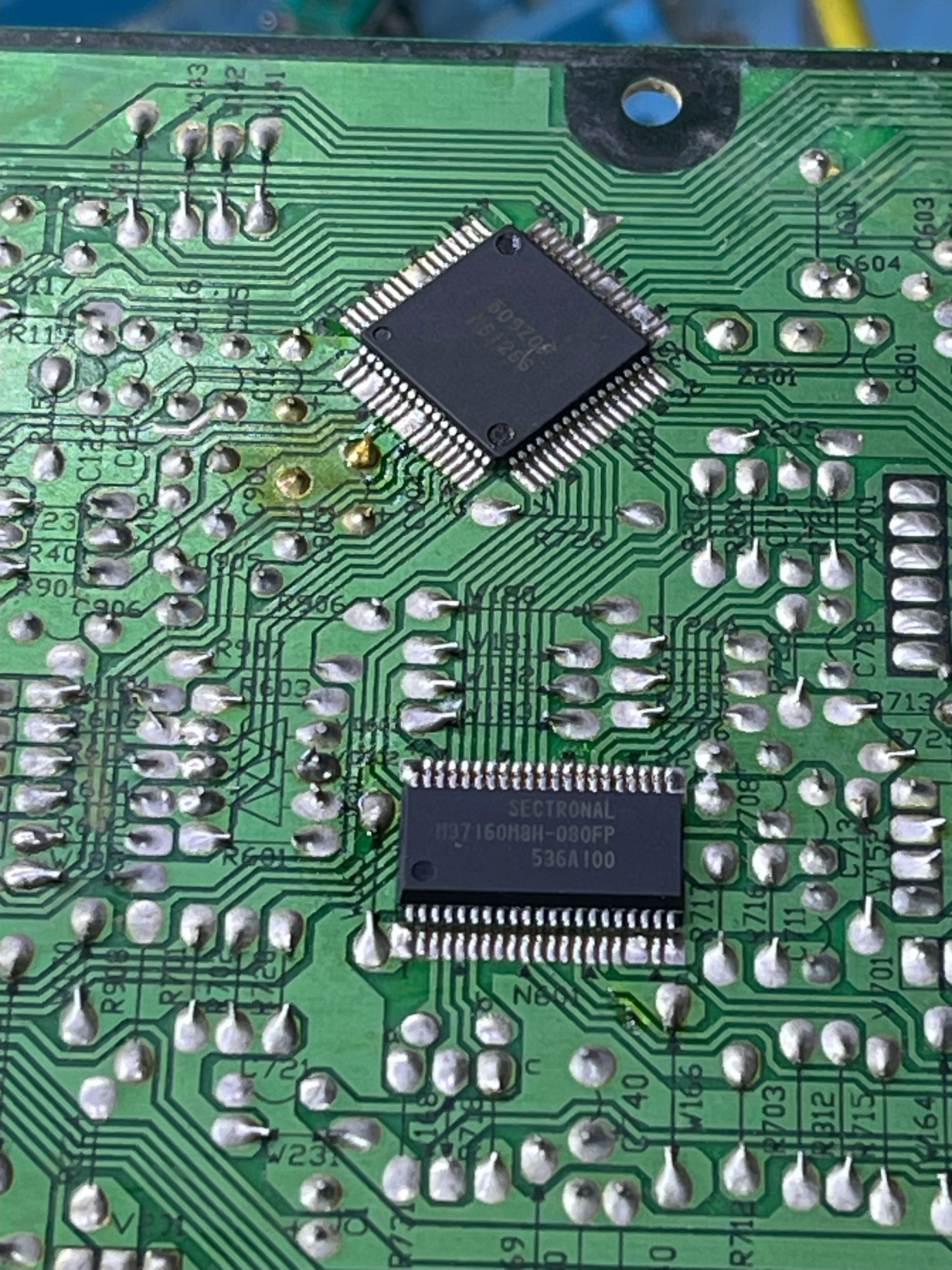
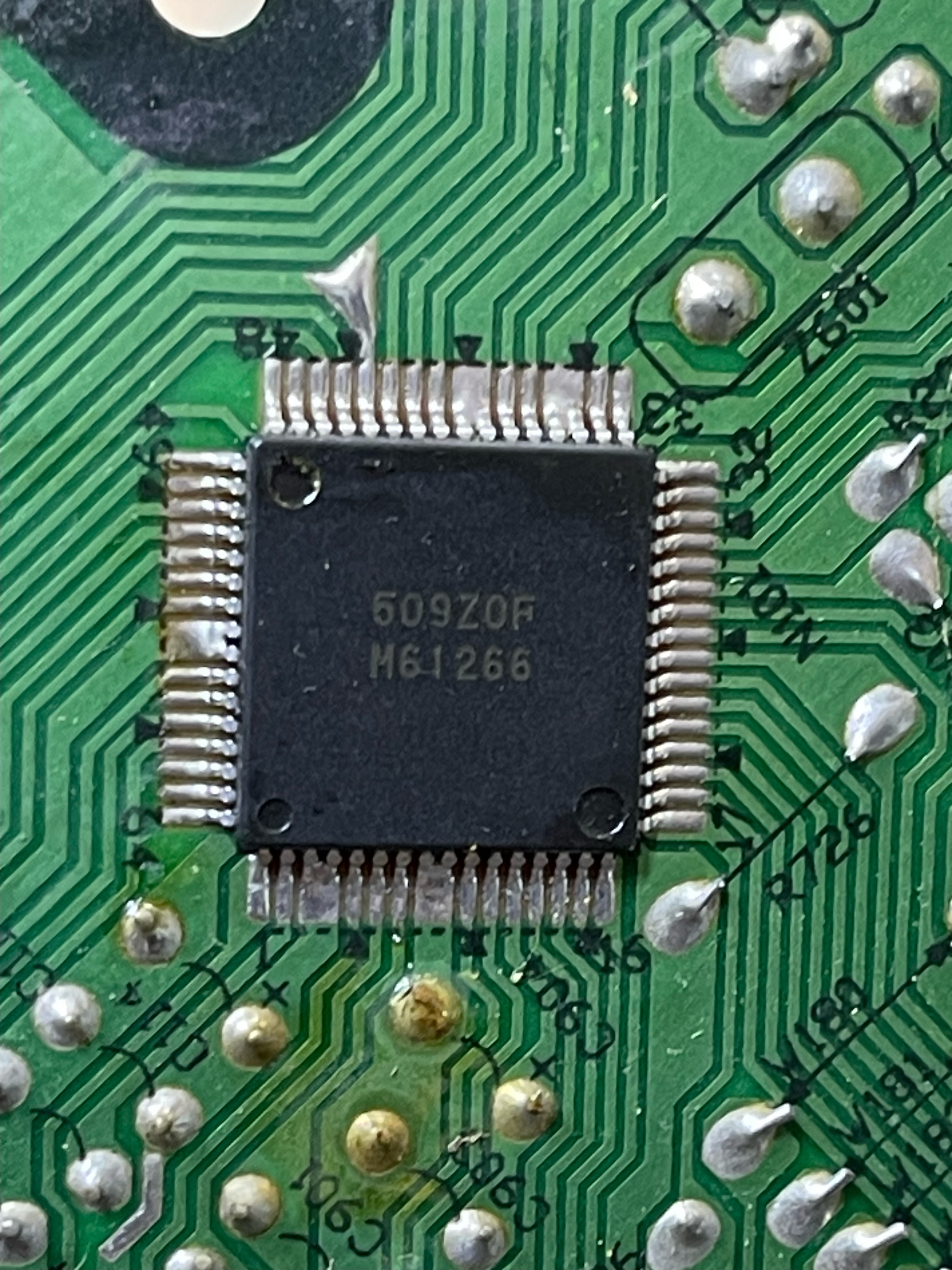
For sync, I’ve tried connecting it to pin 1 on IC201 (pictured) and also pin 6 on IC451, both with the same result.

In my photos is also a drawing I did when I was planning for the mod.

What can I do to fix this? I’m using a csync RGB scart cable with a pal GameCube, as well as a rgb modded n64, which is giving me the same result.

Here is the service manual if needed
https://www.manualslib.com/manual/24903 ... t10x1.html
spikespiegel
Posts: 96
Joined: Wed Jun 16, 2021 12:52 am
Location: Mars

Re: TV RGB mod thread

Post by spikespiegel »

Pikkon wrote: Mon Sep 16, 2024 6:18 am I see,they are a bit different.

This was the best I could find,think maybe one of these sets uses component.
https://elektrotanya.com/panasonic_tc-2 ... ad.html#dl
Mate, I've tested every single value in the Option 5 (twice, now with blanking enabled), now I'm almost half way through Option 6 and still didn't get any results. Am I missing something? I have the caps all set, except the green color, which I'm using as Sync and also connecting the green wire directly to the microcontroller. I have almost 5 volts of power coming from the tunner, I can't remember exactly how much, but it's pretty close to 5 volts and I heard 3.3v is enough, so... I don't know what I'm doing wrong. This project that I'm making is going to be fantastic and I want to post pictures here after I've finished.
User avatar
Pikkon
Posts: 128
Joined: Tue May 26, 2015 6:25 am
Location: Florida

Re: TV RGB mod thread

Post by Pikkon »

I do remember on mine,for the fast blanking there was 8v on that line by default,I just left it alone.

As for enabling component video it could very well be a different option but it's very different than a regular Philips's set.
Post Reply