I don’t think anyone addressed this, but in my opinion it’s a terrible idea: a transcoder shouldn’t need to be connected to wi-fi, as well as be incapable of outputting an interlaced signal. It also chroma subsamples to 4:2:2
GBS 8200/8220 CFW Project
-
kitty666cats

- Posts: 1359
- Joined: Tue Nov 05, 2019 2:03 am
- Location: Massachusetts, USA
Re: GBS 8200/8220 CFW Project
-
kitty666cats
- Posts: 1359
- Joined: Tue Nov 05, 2019 2:03 am
- Location: Massachusetts, USA
Re: GBS 8200/8220 CFW Project
https://www.ebay.com/itm/156201953166
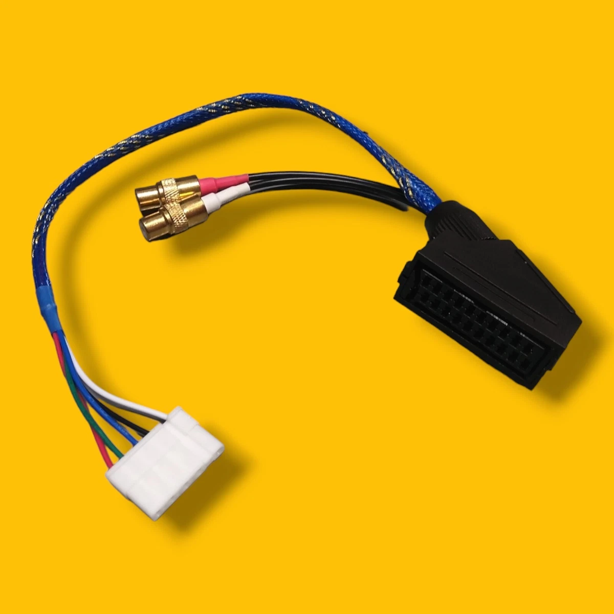
This looks like it could be of good use for any DIY folks who want an easy SCART input. I’m not 100% on what sync voltage/polarity (99.9% sure negative for the latter) the GBS molex input expects, but I’m sure my man No “Master of GBS” Affinity could weigh in with his opinions on if he thinks this would work.
This looks like it could be of good use for any DIY folks who want an easy SCART input. I’m not 100% on what sync voltage/polarity (99.9% sure negative for the latter) the GBS molex input expects, but I’m sure my man No “Master of GBS” Affinity could weigh in with his opinions on if he thinks this would work.
-
NoAffinity

- Posts: 1098
- Joined: Mon May 07, 2018 5:27 pm
- Location: Escondido, CA, USA
Re: GBS 8200/8220 CFW Project
Wow, i'm honored by such a prestigious nickname.kitty666cats wrote: ↑Sat May 25, 2024 8:24 pm https://www.ebay.com/itm/156201953166
This looks like it could be of good use for any DIY folks who want an easy SCART input. I’m not 100% on what sync voltage/polarity (99.9% sure negative for the latter) the GBS molex input expects, but I’m sure my man No “Master of GBS” Affinity could weigh in with his opinions on if he thinks this would work.
I'm assuming it should be 1vpp, with the 100ohm resistor between sync and ground. Basically, the cable should be pass through and the sync to ground resistor should be applied as recommended in order to bring console levels into tolerance for the GBS.
Looks like a cleaner version of what I cobbled together a few years ago, but for the 8p input.
Spoiler

-
strnadik
- Posts: 13
- Joined: Wed May 08, 2024 9:17 am
Re: GBS 8200/8220 CFW Project
Anyyy idea why this is happening? Soldered up a SCART to RGBS input to GBS-C, intercepted with an LM1881N sync stripper built accordingly.
Sidenote: There is a missing cap on the board but i bridged it. Possible cause? I dont know!


Sidenote: There is a missing cap on the board but i bridged it. Possible cause? I dont know!
-
Dailenth
- Posts: 5
- Joined: Thu Apr 18, 2024 9:39 pm
Re: GBS 8200/8220 CFW Project
Hello, I'm afraid none of the currently shipped chinese GBS-C prebuilts have updated firmware. You have to do it yourself. I don't recommend using the MicroUSB method, but use WiFi Flashing instead if you have a spare wifi "dongle" adaptor. I have using the term dongle by the way.Bassa-Bassa wrote: ↑Mon Apr 22, 2024 10:37 pmThanks for sharing. Isn't any of these prebuilt units sold with a properly updated code in 2024?Dailenth wrote: ↑Thu Apr 18, 2024 10:14 pm
The only problem with these open source forks is that they're never maintained, they release version 1.0 and just abandon the sourcecode. Thankfully the official firmware is fully compatible as expected, though you need to compile the code yourself, and follow the steps carefully.
You have to download the official gbsc-control-master.zip from github then follow this guide to flash it. Do exactly as it says or watch a youtube video on how to flash the firmware.
For OTA flash you need to access the ESP8266 wifi via "http://gbscontrol.local" or type the ip in your browser "192.168.4.1"
To access your gbscontrol via wifi you need to select the SSID gbscontrol and password "qqqqqqqq"
Once you access the control panel of your gbsc head to the last tab and select enable OTA and I highly recommend find and enable the "developer tools" because it will display the console to display any progress. DO NOT change anything inside developer tools.
It's hard to mess it up if you follow the guide step by step, I'm here to help for any more questions regarding updating the firmware.
Hope it helps
-
Bassa-Bassa
- Posts: 1714
- Joined: Tue Mar 12, 2019 5:18 pm
Re: GBS 8200/8220 CFW Project
Thanks, mate. I'm sure it'll help. Where can I check to know what exactly I'll be missing if I don't update? My interest in the device is 480p into 240p only.
-
emmeka
- Posts: 16
- Joined: Fri Jul 09, 2021 5:29 am
- Location: ON, Canada
Re: Original xbox wobbly image at 720p
There is no solution. As far as I can tell the GBS-C can't handle HD passthrough at all, it only really accepts SD inputs. I've tried a few times to get it to pass through HD resolutions from various consoles and a PC and it always has major issues. All 720p inputs (RGBHV, RGBS, or YPbPr) from RGBHV output have very shaky sync with very heavy jitter, and if you go into the debug menu and look at the console with a 720p input on it just reports "Sync High!" as an error. The situation for 1080i and 1080p is even worse: 1080i doesn't even hold sync at all for me, while 1080p has even worse sync jitter than 720p and seems to periodically lose sync. It's kind of unfortunate, if you need 720p support you're going to have to look at other scalers or find a way to route them around the GBS-C.CatMachete wrote: ↑Sun May 12, 2024 2:45 pm I’ve seen this issue reported a couple other times but I haven’t seen a solution. I’m using a 1.0 Xbox with cerbios and component cables. 480p games looks great but 720p looks all wobbly and loses sync constantly. If I use a vga to hdmi adapter the image stops wobbling but I still get a black screen every minute or so. I’ve done all the optional mods except replacing c11.
-
CatMachete
- Posts: 3
- Joined: Fri Jan 12, 2024 5:43 pm
How to fix vertical banding?
Edit: and my gbs board just kicked the bucket  i randomly get green lines or sparkles on the image or complete drop outs. Probably toasted something with my soldering iron
I get these annoying equally spaced lines all across my screen when I plug the vga output straight into my monitors, but using a vga to hdmi adapter does get rid of them.

It doesn't show very well in the picture (I don't have a capture card). I'm using a wii with component cables, but it also happens on my xbox. I've done all the mods except the copper tape but idk if that would help or not
I get these annoying equally spaced lines all across my screen when I plug the vga output straight into my monitors, but using a vga to hdmi adapter does get rid of them.
It doesn't show very well in the picture (I don't have a capture card). I'm using a wii with component cables, but it also happens on my xbox. I've done all the mods except the copper tape but idk if that would help or not
-
Freedy
- Posts: 29
- Joined: Wed Jul 31, 2019 8:56 am
Re: GBS 8200/8220 CFW Project
Hello, I am having problem with RGBs, trying to use a SNES with RGB bypass(configured with 39Ohm resistors on the output for PAL SNES scart cable compatibility) and DeJitter mod(borti's SuperCIC mod which has the deJitter integrated in it).
CSYNC ~300mV 75Ohm is used from dejitter mod, my scart cable does not have any additional resistors in the sync line.
I did not have a 100Ohm resistor, so I've put two 47Ohm resistor in series between gnd and sync pins on gbs.
The snes works on CRT with the same cable, but with GBS it seems there is something wrong with the sync, but I do not know what could it be.
Do you have any tips what should I check?
GBS-C finds the sync(with ot without the 2x47ohm resistors between the GBS's sync and ground pins) using a gamecube cable that is wired to use compositve video sync (although Gamecube cables do not have the same resistors for R, G, B lines)
EDIT:
R34 was a 900 something Ohm resisort, replaced it with a 75Ohm resisor, and removed the formerly added resistors. No change. Tried it with PS2 using a sync on luma scart cable, picture is very dark, (works fine with YPbPR)
EDIT2:
for the SNES, it was a grounding issue, for the ps2, I do not know yet why the picture is dark / low contrast, because the picture is dark with a factory(although third party) cable as well. maybe just a bad quality one, maybe I will check the grounding on these cables, too, but probably I will just use a YPbPR cable.
-
twone
- Posts: 1
- Joined: Sun Jun 30, 2024 7:16 pm
Re: GBS 8200/8220 CFW Project
Hey! Just received RetroScaler's GBS Control from AliExpress, this one:
https://www.aliexpress.com/item/1005005104643787.html
Can/should the 3 RGB pots be removed and bridged, or can they just be bridged without removing them? Should I just leave them alone?
https://www.aliexpress.com/item/1005005104643787.html
Can/should the 3 RGB pots be removed and bridged, or can they just be bridged without removing them? Should I just leave them alone?
-
locutus2000
- Posts: 1
- Joined: Mon Jul 01, 2024 8:27 am
Re: GBS 8200/8220 CFW Project
I might have the same issue with my SNES, I made a video: https://www.youtube.com/shorts/mW4r-1B-xUg did you have the same? Was it just that the cable wasn't grounded properly?Freedy wrote: ↑Mon Jun 17, 2024 2:57 pm Hello, I am having problem with RGBs, trying to use a SNES with RGB bypass(configured with 39Ohm resistors on the output for PAL SNES scart cable compatibility) and DeJitter mod(borti's SuperCIC mod which has the deJitter integrated in it).
CSYNC ~300mV 75Ohm is used from dejitter mod, my scart cable does not have any additional resistors in the sync line.
I did not have a 100Ohm resistor, so I've put two 47Ohm resistor in series between gnd and sync pins on gbs.
The snes works on CRT with the same cable, but with GBS it seems there is something wrong with the sync, but I do not know what could it be.
Do you have any tips what should I check?
GBS-C finds the sync(with ot without the 2x47ohm resistors between the GBS's sync and ground pins) using a gamecube cable that is wired to use compositve video sync (although Gamecube cables do not have the same resistors for R, G, B lines)
EDIT:
R34 was a 900 something Ohm resisort, replaced it with a 75Ohm resisor, and removed the formerly added resistors. No change. Tried it with PS2 using a sync on luma scart cable, picture is very dark, (works fine with YPbPR)
EDIT2:
for the SNES, it was a grounding issue, for the ps2, I do not know yet why the picture is dark / low contrast, because the picture is dark with a factory(although third party) cable as well. maybe just a bad quality one, maybe I will check the grounding on these cables, too, but probably I will just use a YPbPR cable.
Update: I found out I purchased a NTSC scart cable instead of a PAL one, I removed the 220uf caps inside and it already works. I've ordered 75 ohm resistors and I will wait for them to arrive to install them.
-
niark
- Posts: 7
- Joined: Thu Jul 04, 2024 2:02 pm
Re: GBS 8200/8220 CFW Project
Hello, I just bought myself a 4K morph and I would like to use my GBS C as a relay.
I see that there is a Through Pass option and then use it for this use case?
What would be the best way to use the GBS C with the morph?
thank you in advance for your help
I see that there is a Through Pass option and then use it for this use case?
What would be the best way to use the GBS C with the morph?
thank you in advance for your help
-
NoAffinity
- Posts: 1098
- Joined: Mon May 07, 2018 5:27 pm
- Location: Escondido, CA, USA
Re: GBS 8200/8220 CFW Project
What is the purpose of chaining the two devices, and what would the order be?
GBSC can theoretically do pass thru up to 1080p. It may struggle with anything over 720p, though, and I would expect it to pass through odd or CP resolutions like 1024x768, etc.
-
orange808

- Posts: 3921
- Joined: Sat Aug 20, 2016 5:43 am
Re: GBS 8200/8220 CFW Project
I assume the purpose is to feed analog sources into the Morph. The Morph is a "retro" video processor that is "designed" to scale video from analog sources with no analog input! (I plan to edit this post later if that changes! See! We all have plans! It's in my roadmap!)NoAffinity wrote: ↑Thu Jul 04, 2024 5:38 pmWhat is the purpose of chaining the two devices, and what would the order be?
As for using a GBS Control as an ADC, it's imperfect. The GBS Control project is a lovely inexpensive option for some consoles, but it's got a lot of limitations, idiosyncrasies, and oddities. There's also not much control over the sampling.
Will it work? Sorta. Sometimes.
I suppose the best ADC option is an OSSC Pro? That means buying an OSSC Pro and a Morph. That's expensive. You may as well just get a Retrotink4k. The RT4k also delivers multiple features in the firmware that you still can't get with the OSSC Pro and Morph combo.
We apologise for the inconvenience
-
niark
- Posts: 7
- Joined: Thu Jul 04, 2024 2:02 pm
Re: GBS 8200/8220 CFW Project
Yes it's good to make it an ADC. I want to use my gbs c that I have had for a few years rather than buying an ossc pro. I'll wait for the analog bridge. But I guess I'm not the only one in this situation and wonder what would be the best way to use it for this, especially in pass-throug mode
-
GlowInTheDarkDisco
- Posts: 2
- Joined: Sat Jul 06, 2024 7:08 pm
Re: GBS 8200/8220 CFW Project
I'm going to be building my own GBS-C but I'm a tad confused on the pros and cons of each GBS 8200 board revision. I'm able to buy a V4 which seems to be recommended but I've also come across V5.1 and V5.2 boards. Is there any reason to pick V4 or the V5+ ones?
Thanks!
Thanks!
-
kitty666cats
- Posts: 1359
- Joined: Tue Nov 05, 2019 2:03 am
- Location: Massachusetts, USA
Re: GBS 8200/8220 CFW Project
Chiming in a few posts late, but:
Another reason a GBS as an ADC bridge is definitely nottt a good idea (aside from the 4:2:2 chroma subsampling on the output) is that all the premade units with HDMI out just have disassembled super-cheapo VGA to HDMIs hardwired to the output. Lord knows how many varying chipsets are used across all those premade units, or how accurate some are compared to others.
Another reason a GBS as an ADC bridge is definitely nottt a good idea (aside from the 4:2:2 chroma subsampling on the output) is that all the premade units with HDMI out just have disassembled super-cheapo VGA to HDMIs hardwired to the output. Lord knows how many varying chipsets are used across all those premade units, or how accurate some are compared to others.
-
orange808
- Posts: 3921
- Joined: Sat Aug 20, 2016 5:43 am
Re: GBS 8200/8220 CFW Project
It's my understanding that the GBS Control oversampling sidesteps the 4:2:2 chroma issue by feeding redundant additional samples early in the processing pipeline. If the GBS Control didn't oversample, the results should look ghastly--much like feeding 240p directly into the DVDO iScan vp50pro without a line doubler.kitty666cats wrote: ↑Tue Jul 09, 2024 3:03 pm Chiming in a few posts late, but:
Another reason a GBS as an ADC bridge is definitely nottt a good idea (aside from the 4:2:2 chroma subsampling on the output) is that all the premade units with HDMI out just have disassembled super-cheapo VGA to HDMIs hardwired to the output. Lord knows how many varying chipsets are used across all those premade units, or how accurate some are compared to others.
One reason you might add the GBS Control to your video chain is the machine's approach to frame cadence. It doesn't use a proper frame lock. Instead, GBS Control uses it's own version of "free run" and (mostly) hides the tear line--and it's low lag. Most video processors are laggy when they attempt frame rate conversion. Additionally, motion looks better, because you don't get as many "studdering" frame pacing artifacts as you might find on many other machines (that use frame rate conversion). The benefit of the GBS Control (when it works) is no drop outs when the signal changes. Of course, some sources don't sync up and I've seen the tear line appear in a few long sessions due to drift.
We apologise for the inconvenience
-
kitty666cats
- Posts: 1359
- Joined: Tue Nov 05, 2019 2:03 am
- Location: Massachusetts, USA
Re: GBS 8200/8220 CFW Project
^ It’s incredibly “extra”, but I’ve used GBSC as a front end to my OSSC on passthrough, heh. I have a 1080p Panasonic plasma and the VGA input is *atrocious*. Not accepting the 1080p signal is whatever; even resolutions it DOES accept just look like complete and horrendous garbage. But GBSC on 1080p + OSSC on passthrough mode is aces.
I even had a happy accident where GBSC with 100% scanline strength combined with the OSSC’s vertical scanlines at 100% and Pre-ADC gain maxed out made a ridiculously good-looking “emulated CRT” look. Curiosly, if you made one single adjustment to those very specific OSSC settings, it looked like absolute dogshit, lol. I think I’ve posted pics of this phenomenon somewhere on this board before.
I even had a happy accident where GBSC with 100% scanline strength combined with the OSSC’s vertical scanlines at 100% and Pre-ADC gain maxed out made a ridiculously good-looking “emulated CRT” look. Curiosly, if you made one single adjustment to those very specific OSSC settings, it looked like absolute dogshit, lol. I think I’ve posted pics of this phenomenon somewhere on this board before.
-
GlowInTheDarkDisco
- Posts: 2
- Joined: Sat Jul 06, 2024 7:08 pm
Re: GBS 8200/8220 CFW Project
For the part where you're adding 10uf SMD Caps size-0805 on-top of each other, would it be better to just remove those SMD Components, and solder an electrolytic capacitor? Someone on the GIthub was suggesting a 100uf 25V, not sure if a 16V would be fine. They did some tests and even confirmed less picture noise:
https://github.com/ramapcsx2/gbs-control/issues/344
This person just used 16V ones:
https://github.com/ramapcsx2/gbs-control/issues/542
https://github.com/ramapcsx2/gbs-control/issues/344
This person just used 16V ones:
https://github.com/ramapcsx2/gbs-control/issues/542
-
Unseen

- Posts: 738
- Joined: Sun May 25, 2014 8:12 pm
- Contact:
Re: GBS 8200/8220 CFW Project
Electrolytic and ceramic capacitors have very different electrical characteristics, so the result could go either way.GlowInTheDarkDisco wrote: ↑Sat Jul 27, 2024 5:01 pm For the part where you're adding 10uf SMD Caps size-0805 on-top of each other, would it be better to just remove those SMD Components, and solder an electrolytic capacitor?
GCVideo releases: https://github.com/ikorb/gcvideo/releases
-
dntm
- Posts: 3
- Joined: Sat Sep 07, 2024 9:53 am
Re: GBS 8200/8220 CFW Project
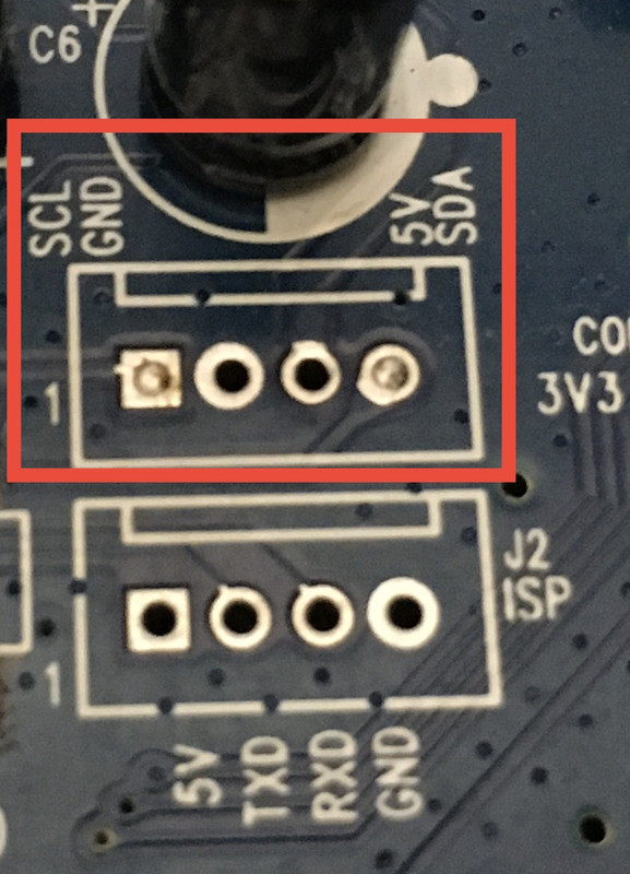
I also have a HD BOX PRO board with TV7025 and MTV230M chips, and it looks like the same structure as the GBS 8200. However, the modifications I made to the GBS 8200 do not work.naldin wrote: ↑Fri Aug 06, 2021 1:56 pmYes my IC is MTV230GMV too. For SCL and SDA look the picture, SCL pin 1 and SDA pin 4. My problem is with disable and debug pins, I need someone that have a GBS to check if this pins go to TVIA IC and if yes, which pins.Guile wrote:That's interesting, on my hd box pro the chip is MTV230GMV. Where did connect SDL and SCA? I see them on the board but I don't know if they work.naldin wrote:
I have the same board and tried used ESP8266 but doesn't work. I saw that this board have different mappings pins in MTV230M, the HD BOX Pro have:
Menu - Pin 25
Down - Pin 26
Up - Pin 27
I saw in picture below that GBS use pin 37, 35 and 34. I think that debug and P8 will have another pins. My question is the debug pin and P8 come from some TVIA pin?
Did you disable the hd box somehow like the gbs needs the jumper? I don't see a similar spot on the hd box.
Don't you only need to connect the single debug pin from that chip to the esp8266?
I think the keypoint is the Debug Pin, because without them you can't skip the original logic. The problem now is that I don't know which Debug Pin is applicable to the HD BOX PRO, or maybe even the HD BOX PRO doesn't have a debug function.
Last edited by dntm on Sat Sep 07, 2024 10:05 am, edited 1 time in total.
-
SMLMcKenzie
- Posts: 28
- Joined: Thu Oct 17, 2024 6:37 pm
Re: GBS 8200/8220 CFW Project
Is there any benefit to building your own DIY GBS C rather than buying an AliExpress one? I am confident in my soldering ability so that is not a problem.
-
NoAffinity
- Posts: 1098
- Joined: Mon May 07, 2018 5:27 pm
- Location: Escondido, CA, USA
Re: GBS 8200/8220 CFW Project
Cost, assuring it's done right and the components being installed are of the quality that you dictate. The challenge will be getting a gbs that is assured to be compatible with gbs control. You can usually communicate with sellers to determine what the date code/revision is (and that they aren't a yellow button model).SMLMcKenzie wrote: ↑Mon Oct 21, 2024 3:37 pm Is there any benefit to building your own DIY GBS C rather than buying an AliExpress one? I am confident in my soldering ability so that is not a problem.
-
MaRCer
- Posts: 11
- Joined: Tue Feb 13, 2024 7:08 pm
Re: GBS 8200/8220 CFW Project
1080p uses non-integer scaling, and if everything looks great with a 240p signal, then 480p already looks bad, artifacts appear in the form of lines and notches on the boundaries of objects. You can turn on 960p resolution, where there will be a normal 4x scale, but this is not the native resolution of my 1080p TV and it stretches and washes it. In 1080p, you can do 4x vertically, set the vertical scaling - vscale to 512, but you can't reduce the horizontal scaling, writes that the limit has been exceeded and the picture eventually turns out to be stretched horizontally - can something be done about it?
-
Iraito
- Posts: 134
- Joined: Sat Aug 24, 2019 8:59 am
Re: GBS 8200/8220 CFW Project
I bought this https://electron-shepherd.com/products/ ... 4R5cueLomt and installed it
Now i get a green output with vertical stripes showing the actual output, any idea of the issue?
Now i get a green output with vertical stripes showing the actual output, any idea of the issue?
-
Iraito
- Posts: 134
- Joined: Sat Aug 24, 2019 8:59 am
Re: GBS 8200/8220 CFW Project
An example of my issue

-
Gunstar

- Posts: 655
- Joined: Wed Apr 09, 2014 10:29 am
- Location: UK
-
Iraito
- Posts: 134
- Joined: Sat Aug 24, 2019 8:59 am
-
Gunstar
- Posts: 655
- Joined: Wed Apr 09, 2014 10:29 am
- Location: UK
Re: GBS 8200/8220 CFW Project
GBS doesn't like RGBHV* (would need a sync combiner) but it shouldn't be heavily messed up with RGBS over SCART hmm
Does your GBS have the 100 Ohm resistor mod mentioned here? in addition to the 100 ohm, adding a Sync stripper might help if you're SCART is wired for Luma or Composite sync.

*for downscaling, I think it will upscale 480p? in that case you need to disable the 100 ohm mod