Matt
TV RGB mod thread
-
Mrmatt3465
- Posts: 6
- Joined: Wed Aug 19, 2020 4:40 am
Re: TV RGB mod thread
So about that  I haven’t been able to find a schematic of a repair manual for this thing either. In order to troubleshoot it and do any repairs, I’ve been tediously looking at traces and following point to point where things lead. It’s very much in the dark but I’ve managed to repair some basic things like no power to the 27v bus or 25v bus by replacing blown diodes and current limiting resistors off the fly back. It’s probably a miracle i fixed anything at all considering most of the time I’m watching videos from guys in India fixing busted up CRT TVs
  I will however see if there are similar chips available that I can potentially get a data sheet for and then I’ll try and validate it on the board itself. I don’t own an oscilloscope, only a cheap DMM but it’s gotten me this far.
Matt
Matt
-
cyborc

- Posts: 308
- Joined: Wed Mar 25, 2009 6:26 am
- Location: USA
Re: TV RGB mod thread
what are the part numbers on the chips themselves? I've noticed on USA Sharp TVs, a lot of times they rebrand other chips with their own part numbers starting with "IX." often times it turns out to simply be a rebranded Toshiba or Sanyo jungle IC.Mrmatt3465 wrote:So about that
Matt
-
tacoguy64
- Posts: 558
- Joined: Tue Dec 30, 2014 12:42 am
Re: TV RGB mod thread
Still working on a JVC AV32D302, was given two weeks to try and work on it before throwing it away.
Last left off I was following the mod from Maxtherabbit on page 102 since it was the same mod. Just copy and paste with the only difference being the scart connector and use the mux method from MarkOzlad. I get a black screen when powering the system, but can see part of the game when i hit the menu button. It's been a while since I last worked on it but my question where how to wire the scart connector exactly, using Max's procedure and Mark's diagram.
Last left off I was following the mod from Maxtherabbit on page 102 since it was the same mod. Just copy and paste with the only difference being the scart connector and use the mux method from MarkOzlad. I get a black screen when powering the system, but can see part of the game when i hit the menu button. It's been a while since I last worked on it but my question where how to wire the scart connector exactly, using Max's procedure and Mark's diagram.
-
Mrmatt3465
- Posts: 6
- Joined: Wed Aug 19, 2020 4:40 am
Re: TV RGB mod thread
IX1736CE and X1078CE. That would make sense. The vertical IC I ordered, I found a website that said the compatible IC was an LA7830 [Sanyo?] yet the Sharp number was like X0640CE. Let me see if I can find anything now after omitting the X or IX.cyborc wrote: what are the part numbers on the chips themselves? I've noticed on USA Sharp TVs, a lot of times they rebrand other chips with their own part numbers starting with "IX." often times it turns out to simply be a rebranded Toshiba or Sanyo jungle IC.
Matt
-
MarkOZLAD
- Posts: 1040
- Joined: Thu May 18, 2017 12:39 pm
Re: TV RGB mod thread
IX1078CE is a TA8601BN equivalent.Mrmatt3465 wrote:IX1736CE and X1078CE. That would make sense. The vertical IC I ordered, I found a website that said the compatible IC was an LA7830 [Sanyo?] yet the Sharp number was like X0640CE. Let me see if I can find anything now after omitting the X or IX.cyborc wrote: what are the part numbers on the chips themselves? I've noticed on USA Sharp TVs, a lot of times they rebrand other chips with their own part numbers starting with "IX." often times it turns out to simply be a rebranded Toshiba or Sanyo jungle IC.
Matt
___________________________________________________
MarkOZLAD
OSD/External RGB Mux Diagram
OSD/External RGB Mux Resistor Value Table 0.7Vp-p : 0.5Vp-p
"Imagine toggle switch OSD modding a TV in 2019" - maxtherabbit
MarkOZLAD
OSD/External RGB Mux Diagram
OSD/External RGB Mux Resistor Value Table 0.7Vp-p : 0.5Vp-p
"Imagine toggle switch OSD modding a TV in 2019" - maxtherabbit
-
Osirus

- Posts: 218
- Joined: Tue Jun 16, 2020 8:51 pm
Re: TV RGB mod thread
If you see your injected RGB through the OSD text it sounds like your have your blanking voltage level wrong.tacoguy64 wrote:Still working on a JVC AV32D302, was given two weeks to try and work on it before throwing it away.
Last left off I was following the mod from Maxtherabbit on page 102 since it was the same mod. Just copy and paste with the only difference being the scart connector and use the mux method from MarkOzlad. I get a black screen when powering the system, but can see part of the game when i hit the menu button. It's been a while since I last worked on it but my question where how to wire the scart connector exactly, using Max's procedure and Mark's diagram.
-
Mrmatt3465
- Posts: 6
- Joined: Wed Aug 19, 2020 4:40 am
Re: TV RGB mod thread
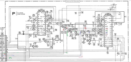
Thank you for this info! Using this, tonight I traced the circuit from the X1078CE to the Jungle IC IX1736CE and here is what I came up with:MarkOZLAD wrote:IX1078CE is a TA8601BN equivalent.

I used a web page style diagram maker since my hand drawn diagram was doo doo so hopefully this isn't horrendous to look at. I progressively got better at the diagram maker after using it for a bit.
I found that the blanking voltage leaving IC401 is 4.9V and is 8mV once it gets to pin 40 at the jungle IC IC3101. The RGB signals are 5.3V leaving IC401 and are 7.7mV once they enter IC3101. IC3102 is some strange looking IC thats kind of bubbly looking. Looks like maybe a chip with transistors on it and then the whole thing was covered in a heat shrink? Its marked Sharp Z0081CE. Based on observations from its traces, a set of traces led to the jungle, and the other set led to the neck board for color attenuation.
So my next few questions are as follows: Do I add up all the resistors in line between the IC401 and the Jungle [2530ohms?] and then use that as my "in-line resistor" which would lead me to need a 330-390ohm resistor on my RGB lines with 75ohm termination to ground injected at the Jungle IC IC3101 between R3230, R3228, and R3229? For the BLK line, should I find a 5V source and then give it a 1.3k resistor and feed it to the jungle after R3143? Since I'm doing this mod internal to the TV with the Super Famicom build in, I won't need a SCART connector or anything, so can I just snag the RGB and CSync signals straight from the pins of the Multi AV and then appropriately input them as above? Would I tag CSync with a 330-450ohm resistor [SNES CSync output is TTL] to the Composite Yellow jack and then use Video 1 as my input whenever I use the SFC? Finally, what is the use in using diodes on the RGB lines leaving the OSD chip?
I realize some of this is 100% unknown as I think I'm the only one to have attempted this. But if I get it working I'll gladly "dumb it down" for this thread so its easier for anyone else to attempt.
Thanks for your time.
Matt
-
hotdogs_stuff
- Posts: 2
- Joined: Thu Dec 10, 2020 5:55 pm
Re: TV RGB mod thread
i have this exact same trinitron, I will try to attach the jungle chip. I am not an electrical novice (i can read a schematic but the television terminology is new to me) and i have modded several of my consoles myself. i wanted to RGB mod this television which was manufactured in the US in 1996. if a component (ypbpr) mod is possible i would prefer that as i have already purchased HDretrovision cables for all my consoles (which is not a big deal to replace them with scart, but if the component mod is possible it is preferred).maxtherabbit wrote:has anyone ever tried YPbPr modding a 90s curved trinitron?
I was looking at one service manual for the kv-32s22, which uses the CXA2025AS Y/C/J, and it appears to take YUV at the correct levels from the PiP board... seems like a component mod for that jungle chip would be a breeze
my questions are:
1- if the mod is possible for this TV, which inputs on the jungle chip would i use. being new to the terminology I can't make sense of the pins and my schematic for my Sony Wega (which does have component inputs) uses completely different terminology for the pins.
2- if the component mod is not possible can someone please point me to some reference resources for the RGB mod? I am not sure if the scart input needs to run to the jungle chip's inputs or outputs, and exactly how to set up the capacitors and resistors. the TV is still useful to me because it has s-video so i'd hate to blow it up because i didn't fully comprehend what i was trying to do.
thanks in advance.
 IMG_8026 by hotdog stuff, on Flickr
-
retromaniak
- Posts: 45
- Joined: Wed Dec 26, 2018 9:51 am
Re: TV RGB mod thread
Hi, i have a question. How step by step install RGB mod into this TV? I'm don't understand analog electronic (i can read schematic picture but that's all) I have only RGB picture on this tv... Sorry for my terrible english and thanks for responce.
This is TV Service Manuał
https://drive.google.com/file/d/1S0s3Rk ... p=drivesdk
And this is chroma decoder datasheet
https://drive.google.com/file/d/1Muiwen ... p=drivesdk
P.S. optionally, instead of RGB mod, I also thought about installing component (if it would be easier to implement)
This is TV Service Manuał
https://drive.google.com/file/d/1S0s3Rk ... p=drivesdk
And this is chroma decoder datasheet
https://drive.google.com/file/d/1Muiwen ... p=drivesdk
P.S. optionally, instead of RGB mod, I also thought about installing component (if it would be easier to implement)
-
vol.2

- Posts: 3292
- Joined: Mon Oct 31, 2016 3:13 pm
- Location: bmore
Re: TV RGB mod thread
I think that IC only accepts composite. If I had to guess, composite input is pin 14 on IC7901. It shows some kind of a composite input in the schematic where it shows VIDEO IN VIDEO out. If your set doesn't have that (it would probably be a small headphone type plug hole on that kind of portable set) then you could definitely add it somehow. Problem is the schematic is not very helpful and the datasheet is unavailable. If it was me, I would give up on that set and try a different one.retromaniak wrote:optionally, instead of RGB mod, I also thought about installing component (if it would be easier to implement)
-
retromaniak
- Posts: 45
- Joined: Wed Dec 26, 2018 9:51 am
Re: TV RGB mod thread
It's true, but I heard that you can still make a mod ...vol.2 wrote:I think that IC only accepts composite.
-
vol.2
- Posts: 3292
- Joined: Mon Oct 31, 2016 3:13 pm
- Location: bmore
Re: TV RGB mod thread
You would have to work out how to build a new output stage. You couldn't use the IC that's in there. It would be a monumental task. IMHO, that set isn't worth the trouble. On top of that, the schematic sucks and there aren't any datasheets for the ICs available. I would recommend finding a new one.retromaniak wrote:It's true, but I heard that you can still make a mod ...vol.2 wrote:I think that IC only accepts composite.
-
retromaniak
- Posts: 45
- Joined: Wed Dec 26, 2018 9:51 am
Re: TV RGB mod thread
Ok, thanks for responce.
-
ektroy
- Posts: 2
- Joined: Sun Dec 13, 2020 10:51 am
Re: TV RGB mod thread
Hello everyone long time lurker first time poster, decided to plunge into modding my trinitron I had in my garage looked through a lot of pages doing research and was wondering if anyone has had any luck with this tv?
Tv: Kv-27v55
Service Manual: https://elektrotanya.com/sony_kv-27v55. ... nload.html
https://elektrotanya.com/sony_kv-27v55_ ... nload.html
Jungle CXA1465AS datasheet: https://www.alldatasheet.com/datasheet- ... 465AS.html
Tv: Kv-27v55
Service Manual: https://elektrotanya.com/sony_kv-27v55. ... nload.html
https://elektrotanya.com/sony_kv-27v55_ ... nload.html
Jungle CXA1465AS datasheet: https://www.alldatasheet.com/datasheet- ... 465AS.html
-
ektroy
- Posts: 2
- Joined: Sun Dec 13, 2020 10:51 am
Re: TV RGB mod thread
So after waiting for my post to approve I did some more research, on the CXA1465AS there are:
Ys 15
A R IN 16
A G IN 17
A B IN 18
Based off of another post I seen I could pull 16 17 18 Inject there and run 4.5V to Ys via 1k/1k voltage divider from Vcc 2 in which case that input could be blocked by the i2c. How can i tell if its blocked? Pull 16-18 and apply 4.5V to Ys and see If I get an input?
Also I found these pins but they appear to be digital? Can I use a digtal input if the analog is blocked?
OSD BLK 9
D B IN 10
D B IN 11
D B IN 12
-
hotdogs_stuff
- Posts: 2
- Joined: Thu Dec 10, 2020 5:55 pm
Re: TV RGB mod thread
I have this same TV, and I was very curious about your post. I am new to RGB TV modding, so i don't understand all the terms YET, but i am learning. I spent a lot of time pouring over the wiring diagrams and found it does have a signal that converts video from the video switcher to ypbpr video (through a series of transistors and resistors right out of the PIP chip, and there is a signal wire (pip blanking wire) there for PIP, but I am ASSUMING that the "pip" in the chips name stands for Picture in picture, and if that is the case then according to the owners manual that signal would only be displayed in a 1/9th or 1/16th portion of the screen.maxtherabbit wrote:has anyone ever tried YPbPr modding a 90s curved trinitron?
I was looking at one service manual for the kv-32s22, which uses the CXA2025AS Y/C/J, and it appears to take YUV at the correct levels from the PiP board... seems like a component mod for that jungle chip would be a breeze
ended up being the slightly older version of the chassis that uses the CXA2025S - it does have PiP and still takes analog YUV on the same pins, but it doesn't have the EY-SW register to worry about
it also has an analog RGB OSD, so I guess I can bang out both inputs
I'll post back whenever I get around to it, probably be a while
I imagine you could probably run your ypbpr signal through a chip like LMH1251 (texas instruments) inside the TV on a PCB board and use that RGB signal to over-ride the On Screen Display of the RGB. at least then you could still use component cables. there are a couple sections of the board that look like they function the same as the LMH1251 chip (for instance the area of transistors around the PIP, and the tuning micom) and one of them (around the micom chip) may actually convert "video 1" into RGB, but i wouldn't altering your board enough to use those areas of the boad to convert your signal. with out permanently altering the TV i think your only options are RGB from the OSD or component to a LMH1251 chip and then into the OSD RGB lines.
 ypbpr converter off pip by hotdog stuff, on Flickr
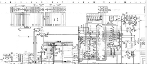 pip to av board by hotdog stuff, on Flickr
 jungle chip by hotdog stuff, on Flickr
-
cartoonhead
- Posts: 2
- Joined: Wed Dec 23, 2020 4:44 am
Re: TV RGB mod thread
I've just gotten a free jvc_av-27430 which has an amazing picture, and I'd like to RGB mod it but I don't quite know where to begin. Think I've found the microcomp chip... Can anyone take a peek at the schematic?
It's here: http://www.cartoonmonkey.com/adrian/jvc_av-27430.pdf
Cheers
It's here: http://www.cartoonmonkey.com/adrian/jvc_av-27430.pdf
Cheers
-
dipslet
- Posts: 1
- Joined: Thu Dec 24, 2020 3:11 am
Re: TV RGB mod thread
Hello my friends) Sorry for my English. I have a problem with mod my Sony KV-G14M1 Trinitron. Chassic BG-1S. I find this "famous" CN106 connector (model without teletext module) and soldered into this connector. RGB signal throught 0.1 ceramic cap and 75 Ohm resistor terminated on ground. In BLK hole, i put 3.3v from voltage regulator LM2931. Burned on TV, i see a picture from composite, when i turned on DPT switch, i seen a black screen (may be OSD ??) and nothing. Okay, i replaced 3.3v regulator on 7805 5v, but nothing changes. Help me please!
-
Cooperd9
- Posts: 37
- Joined: Fri Aug 28, 2020 8:12 pm
Re: TV RGB mod thread
I'm planning out an rgb mod for a KV32S65 trinitron I picked out today, I'm planning on trying out the OSD mux method on this but I'm having a bit of trouble. Does anyone know how to calculate the values for the resistors on the SCART RGB signals? My tv uses 0.7Vp2p rgb signals but has smaller OSD in-line resistor values that aren't included in the table. Specifically, the resistors on the RGB lines are 100 Ohms according the service manual, which I sanity checked with my multimeter after seeing that the smallest resistor listed in the tables is 620ohms, but still got 100 ohms for the resistors. (also, the in-line resistors and capacitors are all SMDs, so getting all of this to fit will be tricky but I should be able to manage, although I might have to use some axial resistors of the same value)
In case anyone needs the relevant portion of the service manual, here is the jungle IC
https://imgur.com/a/Tw72k1c

Edit: also, does anyone have any advice on some kind of quick connect/disconnect system for my Scart connector? It looks like I will have to mount it into the rear half of the TV case and it would be impractical to solder the signal wires when it is mounted into the case or to mount it while it is wired up to the pcb. I have some spare header pins and header sockets so I could probably solder ribbon cables onto those but I don't know if it would cause interference or other problems.
In case anyone needs the relevant portion of the service manual, here is the jungle IC
https://imgur.com/a/Tw72k1c
Edit: also, does anyone have any advice on some kind of quick connect/disconnect system for my Scart connector? It looks like I will have to mount it into the rear half of the TV case and it would be impractical to solder the signal wires when it is mounted into the case or to mount it while it is wired up to the pcb. I have some spare header pins and header sockets so I could probably solder ribbon cables onto those but I don't know if it would cause interference or other problems.
-
Cooperd9
- Posts: 37
- Joined: Fri Aug 28, 2020 8:12 pm
Re: TV RGB mod thread
That jungle ic does take an rgb input, so it should be suitable for an rgb mod as long as it uses analog rgb (some use digital rgb signals that only support a few shades) the blanking pin is pin 17, labeled YS, which seems to be a common descriptor for blanking. The RGB inputs that you should be sending your signals from the scart connection to are pins 18, 19, and 20 (rin is r input etc.) how exactly you wire it up will depend on whether you use the mux method or the older lifted pins method that isn't reccomend.hotdogs_stuff wrote:i have this exact same trinitron, I will try to attach the jungle chip. I am not an electrical novice (i can read a schematic but the television terminology is new to me) and i have modded several of my consoles myself. i wanted to RGB mod this television which was manufactured in the US in 1996. if a component (ypbpr) mod is possible i would prefer that as i have already purchased HDretrovision cables for all my consoles (which is not a big deal to replace them with scart, but if the component mod is possible it is preferred).maxtherabbit wrote:has anyone ever tried YPbPr modding a 90s curved trinitron?
I was looking at one service manual for the kv-32s22, which uses the CXA2025AS Y/C/J, and it appears to take YUV at the correct levels from the PiP board... seems like a component mod for that jungle chip would be a breeze
my questions are:
1- if the mod is possible for this TV, which inputs on the jungle chip would i use. being new to the terminology I can't make sense of the pins and my schematic for my Sony Wega (which does have component inputs) uses completely different terminology for the pins.
2- if the component mod is not possible can someone please point me to some reference resources for the RGB mod? I am not sure if the scart input needs to run to the jungle chip's inputs or outputs, and exactly how to set up the capacitors and resistors. the TV is still useful to me because it has s-video so i'd hate to blow it up because i didn't fully comprehend what i was trying to do.
thanks in advance.
Edit: I fixed some goofy autocorrect from earlier, I shouldn't have tried to post from my phone at 1:00AM. Also did a bit more digging on the component mod options.
As for your component mod question, I haven't seen much about doing a component mod, but if you do want to look into it, your jungle does have YUV inputs. I couldn't find a datasheet for your jungle, but I am working on a similar trinitron with a similar jungle chip, and I could find its data sheet. You should easily be able to find a data sheet for a CXA2095S very easily, and its pinout is similar. On my jungle IC, YUV SW switches between Y/C and YUV input on the jungle, so you would need to tie it high, then EYIN takes the Y signal, ERYIN takes the R-Y, and EBYIN takes the B-Y signal. I don't know a ton about how component video works and there seem to be a bunch of different abbreviations for the same thing, but I think Y corresponds to the green RCA connector, R-Y corresponds to the red (video) connector, and B-Y corresponds to the blue connector, but you are probably going to need to use some resistors and capacitors to attenuate the signals properly, and that is well beyond my knowledge. Also, you can't tell what the target peak-peak voltage for your jungle IC would be without a data sheet, so you are probably going to need to use potentiometers instead of resistors and do a lot of experimenting there. Maybe someone else knows what you need to do better than I do.
-
Osirus
- Posts: 218
- Joined: Tue Jun 16, 2020 8:51 pm
Re: TV RGB mod thread
No, you cannot use digital RGB inputs for a mod. The quickest way to check if your analog inputs are disabled is to put the TV on the TV input (static) and apply voltage to Ys 15. If the screen goes solid black when you do then the mod will probably work.ektroy wrote:So after waiting for my post to approve I did some more research, on the CXA1465AS there are:
Ys 15
A R IN 16
A G IN 17
A B IN 18
Based off of another post I seen I could pull 16 17 18 Inject there and run 4.5V to Ys via 1k/1k voltage divider from Vcc 2 in which case that input could be blocked by the i2c. How can i tell if its blocked? Pull 16-18 and apply 4.5V to Ys and see If I get an input?
Also I found these pins but they appear to be digital? Can I use a digtal input if the analog is blocked?
OSD BLK 9
D B IN 10
D B IN 11
D B IN 12
Edit: Yours looks like those inputs are used for Closed Captioning so they may be enabled. I found a better service manual for it: https://elektrotanya.com/sony_kv-27v55_ ... ad.html#dl
Last edited by Osirus on Thu Dec 31, 2020 3:11 pm, edited 1 time in total.
-
Osirus
- Posts: 218
- Joined: Tue Jun 16, 2020 8:51 pm
Re: TV RGB mod thread
AA-2D chassis. Very common and done numerous times in this thread. I did it a couple of months ago here: viewtopic.php?f=6&t=56155&p=1429634&hil ... 6#p1429634Cooperd9 wrote:I'm planning out an rgb mod for a KV32S65 trinitron I picked out today, I'm planning on trying out the OSD mux method on this but I'm having a bit of trouble. Does anyone know how to calculate the values for the resistors on the SCART RGB signals? My tv uses 0.7Vp2p rgb signals but has smaller OSD in-line resistor values that aren't included in the table. Specifically, the resistors on the RGB lines are 100 Ohms according the service manual, which I sanity checked with my multimeter after seeing that the smallest resistor listed in the tables is 620ohms, but still got 100 ohms for the resistors. (also, the in-line resistors and capacitors are all SMDs, so getting all of this to fit will be tricky but I should be able to manage, although I might have to use some axial resistors of the same value)
You're looking at the wrong resistors. R1123, R1128, and R133 are the grounding resistors to remove, they are on the output of the Digital-Analog conversion circuit for the OSD.
-
Cooperd9
- Posts: 37
- Joined: Fri Aug 28, 2020 8:12 pm
Re: TV RGB mod thread
Thanks for replying, IDK why I didn't think to check the chassis number, but that should help a lot. Now I just need to order resistors in the right sizes and figure out where I want to mount my scart connector. I guess I will be reporting back when I get the parts, but shipping has been extremely slow lately.
-
fixxer2525
- Posts: 1
- Joined: Sun Jan 03, 2021 12:52 am
Re: TV RGB mod thread
I know this is an old thread, but I was wondering KnuckleheadFlow would it be possible to buy one of your rgb mod pcbs to "officially" mod my television. I did it the standard way for the most part since I was uncertain if I need to add resistors or capacitors to the scart socket I added. Any information you could give me would be great and you can contact me here or my email which is [email protected]. Thank-you in advance.
-
tongshadow
- Posts: 693
- Joined: Sat Jan 07, 2017 5:11 pm
Re: TV RGB mod thread
I'm aware this is a very generic question regarding the mod, but let's say if the schematic shows 22nF capacitors in series should be used for the RGB lines, would it still better to use 100nF capacitors instead? Every tutorial/schematic I see uses 100nF capacitors.
Have any of you used such values instead of what the original schematic asks?
Have any of you used such values instead of what the original schematic asks?
-
Osirus
- Posts: 218
- Joined: Tue Jun 16, 2020 8:51 pm
Re: TV RGB mod thread
When injecting into an existing OSD circuit I've always just kept whatever existing caps there are in place. I use 100nF if adding my own (such as injecting into unused RGB inputs on the jungle, etc.).tongshadow wrote:I'm aware this is a very generic question regarding the mod, but let's say if the schematic shows 22nF capacitors in series should be used for the RGB lines, would it still better to use 100nF capacitors instead? Every tutorial/schematic I see uses 100nF capacitors.
Have any of you used such values instead of what the original schematic asks?
-
tongshadow
- Posts: 693
- Joined: Sat Jan 07, 2017 5:11 pm
Re: TV RGB mod thread
Im getting massive color bleeding to the right and it looks rather blurry on my mod. The manual has 22nF caps in series for a similar model that supports component and uses the same chip, so maybe 100nf would be more ideal for RGB?
-
kitty666cats

- Posts: 1359
- Joined: Tue Nov 05, 2019 2:03 am
- Location: Massachusetts, USA
Re: TV RGB mod thread
[quote="Osirus"]No, you cannot use digital RGB inputs for a mod./quote]
You can on certain TVs / monitors at least, my buddy has modded some fancy high end 80s consumer CRTs with digital RGB inputs and made then switchable between analog RGB and digital/CGA/RGBI/whatever folks want to call 'em! Obviously a much more involved process than re-routing some Jungle IC, though...
You can on certain TVs / monitors at least, my buddy has modded some fancy high end 80s consumer CRTs with digital RGB inputs and made then switchable between analog RGB and digital/CGA/RGBI/whatever folks want to call 'em! Obviously a much more involved process than re-routing some Jungle IC, though...
-
chrisrik
- Posts: 5
- Joined: Mon Jan 04, 2021 12:10 am
Re: TV RGB mod thread
Hi,
I am not an expert in electronics by any means, but I have been reading through the required steps to do the OSD Mux mod for a trinitron with a BA-5D chassis. I recently acquired a trinitron TV and after reading the threads on this forum, thought I would do the mod to mine. As it turns out my model (2004 KV-27FS100L) has a BA6 chassis, which in looking at the service manual is different than the BA-5D. Does anyone know where I can find a guide to modding this chassis? Or if not the area on the A board that I should be looking at to piece together how to do this mod for this chassis?
Here is a clip of the board that I thought would at least tell part of the story. Any help is appreciated...it seems like this is a great forum with a bunch of knowledgeable helpful people.
-
Cooperd9
- Posts: 37
- Joined: Fri Aug 28, 2020 8:12 pm
Re: TV RGB mod thread
I'm having what appears to be sync issues on this KV32S65. I have pin 19 of the scart connector wired directly to the luma pin (no ground termination or other resistors) of the tv's s-video input. The R, G, and B signals have 35 ohm terminations to ground and 330 ohm inline resistors. Does anyone know why I would be getting this scrolling effect?
https://imgur.com/MmFoZdn

https://imgur.com/MmFoZdn