

Im not a TV guru, but looks like u cant leave OSD because of this IC(But i can be wrong)laikmike wrote:Theres no way i can get OSD with rgb?obr wrote: Here:
https://imgur.com/vclr9UN
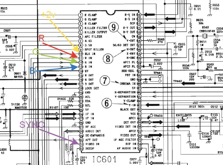
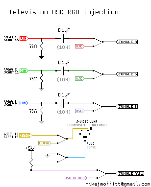
You need to cut those lines, also you will need put here also some caps and terminate this input to ground with 75 ohm
Should be good, but you will lose all OSD and TV features
about the others tv features i dont mind about it, also which cap do I have to use?
thanks for your replys BTW
This jungle doesn't have any RGB inputs, only outputs.laikmike wrote:Directly to tube is to the pcb behind the tube?obr wrote:I guess(not sure) that jungle and controller are combined in this IC. You can try to connect RGB lines directly to tube (before amps ofcourse)laikmike wrote:Hello everyone!, hope you can help me with my TV, I want to make the RGB MOD, but i was checking the diagram of my TV (Panasonic CT-F2128S) in the IC601 chip does not have RGB IN just RGB OUT and I dont know if i can perform the mod on this TV also i think is converting RGB to YUV but Idk...
Hope you can help me
i will add a photo
edit: I dont know if the IC601 is the jungle chip
edit2: here are the diagramshttps://diagramas.diagramasde.com/otros ... is_gl1.pdf
abispac wrote:Hey guys, new guy here i came from the boyac forums looking for help. I got one small 13 inch tv Zanyo, with jungle chip LA7674 and tuning control LSC420142. I think i understand the most , but i just wanted to post here just to make sure i dont screw up. So my question is, based on the schematic, i should solder my rgb cables on jungle 15,16,17 or 18,19,20? i know the 5v i should solder them to -Y in 21, right? And since this particular tv does not have those rca video entrances, should i get the vsync from the tuning chip at 25,24? thanks for any help.
So this jungle chip CANT take RGB MOD?MarkOZLAD wrote:This jungle doesn't have any RGB inputs, only outputs.
I would think it to be possible when reading the datasheet, but it seems to need some looking into, because the way its written on how it works looks a bit confusing to me... If I am not completely off, B should be offset 1.5V for the blanking to occur...MarkOZLAD wrote:abispac wrote:Hey guys, new guy here i came from the boyac forums looking for help. I got one small 13 inch tv Zanyo, with jungle chip LA7674 and tuning control LSC420142. I think i understand the most , but i just wanted to post here just to make sure i dont screw up. So my question is, based on the schematic, i should solder my rgb cables on jungle 15,16,17 or 18,19,20? i know the 5v i should solder them to -Y in 21, right? And since this particular tv does not have those rca video entrances, should i get the vsync from the tuning chip at 25,24? thanks for any help.
I can't be sure because I've never encountered this jungle but it looks like it is designed mainly for OSD purposes only. The Blue in is also the blanking signal. I don't think it will be moddable (via Jungle GB injection) but happy to be proven wrong. 15, 16 and 17 are the inputs.
Unless you figure out if the YUV inputs can be changed to RGB instead (by I2C communication) by finding the datasheet or something, then seemingly no. You can of course install an internal RGB->YUV transcoder...laikmike wrote:So this jungle chip CANT take RGB MOD?MarkOZLAD wrote:This jungle doesn't have any RGB inputs, only outputs.

Hey that was me. I actually don't mind doing SCARTS. Joe wanted BNCs because he's setup to route his audio through a sound system and wanted to have BNCs. The customer is always right!maxtherabbit wrote:Hey the game sack video used the mux! And BNCs to boot! No switch garbage and no heinous SCART plug
Nice job. My only critique would be to say the RGB wires were excessively long.suprcrackers wrote:Hey that was me. I actually don't mind doing SCARTS. Joe wanted BNCs because he's setup to route his audio through a sound system and wanted to have BNCs. The customer is always right!maxtherabbit wrote:Hey the game sack video used the mux! And BNCs to boot! No switch garbage and no heinous SCART plug
The cable was that way because of the BNC panel mount connectors I had on hand. They were orientated in a way where they had to be mounted in the front and locked into place with a nut in the back. So that means I had to mount the connectors to the back of the set, then solder on the wires. Unlike say a scart where I could just cut the hole and the screw locations, push the scart which is already soldered through the hole from the back side and screw it in from the front. All of this could have been helped if I had some connectors on me which would have allowed me to just rejoin the cable together once I had the BNCs mounted, but this was a last second kind of deal. I live in a part of South Dakota which is about 10 hours away from Denver. I was there because my son gets treatment for his liver disease every six months at Colorado Children's hospital. I forgot my connectors at home along with my step bit of all things. Luckily Joe has some drill bits which worked in a pinch.maxtherabbit wrote:Nice job. My only critique would be to say the RGB wires were excessively long.suprcrackers wrote:Hey that was me. I actually don't mind doing SCARTS. Joe wanted BNCs because he's setup to route his audio through a sound system and wanted to have BNCs. The customer is always right!maxtherabbit wrote:Hey the game sack video used the mux! And BNCs to boot! No switch garbage and no heinous SCART plug
I hate SCART hard, but BNC, RCA or VGA are all cool


It's a common misconception that the pins need 0.5V, it needs *at least* 0.5V to switch. However that voltage will vary some, and it could be it works when you're in the middle position and thus the input is floating (which is a bad thing). Instead put a 10K pulldown resistor on it, and then only switch 5V in, so you don't have any undefined states, either it's pulled to GND by the 10K resistor, or you have 5V on it.F-Bomb wrote:I'm not sure if this'll come out in order, as I haven't seen my original post go up yet.
Anyway...
I seem to have had success with the NEC FS68v80. After reading a few of the posts, and watching a couple of video's on youtube. I saw how important it seems to ground all 'ground' pins on the scart plug.
I also got inspired by MarkOZLAD's external MUX and ran s-video and audio from the AV1 sockets into the Sync pins and audio pins respectively on the scart plug. This solved both the no audio and Luma sync issues I was having before.
Now the thing I can't explain. According to the Toshiba TB1227BN data sheet, pin 22 needs 0.5v to activate RGB mode. So as I stated in the past post I used a 2 throw switch to change from ground to 0.5v.
It says linear RGB input so pretty sure it's not digital. Also you can simply create a DC offset to your signal to obtain the switch voltage. There are many ways to do this depending on your requirements, with the simplest being a voltage divider with your signal coming in "in the middle" to using an om-amp to sum voltages.SlightlyObsessed wrote:I’m in the exact same boat as (at least) two other posters on the thread. The jungle IC I’m looking at has blue and blanking on the same input.
The chip is the same mentioned by abispac above which is a LA7674. It also resembles an earlier post by thedudeabides (page 94) with a LA7672.
https://www.audiolabga.com/pdf/LA7674.pdf
I’m unable to tell if the IC is digital only and how to supply blanking and blue to the same pin (pin17).
I corrected the image on Panasonic using the service menu of the TV, I could not tear it apartobr wrote:Could you please show a picture of wrong geometry?Surfovod wrote:Hello.
I have a TV Panasonic TC-2155R, with a chassis MX-3C http://gaf.kz/tv/AN.PDF, a video processor AN5192K http://gaf.kz/tv/MX.pdf.
I want to connect a 60-in-1 Chinese gaming board for vertical games.
Connected according to the picture. I picked up all the necessary resistances and ceramic capacitors. The colors are very good, bright, they delight me, but there is one problem - the geometry of the picture is broken (the image is shifted). I read the whole topic, I realized that the reason for this is a comb filter. It is recommended to connect directly to the luma S-video, but I do not have such an input, only composite (AB). I tried to connect directly to Y-in (43) and CHROMA-in (48) there is no effect, I even tried to connect to the contacts of vertical and horizontal synchronization (45,46) (the geometry is not straightened). I would configure the geometry through the service menu, but the original remote is lost, I don’t know how to enter the service menu without it.
I am in despair, ready to throw the TV into the abyss.
Please tell me how to get around this comb filter? are there any methods?
Or maybe it is possible to enter the service menu without the original remote?
I would be grateful for any help

Thanks skum that gives me hope. Requirements would be to send the standard voltage (with 75ohm termination) on the blue line for video termination including both the blue signal and the required blanking (pulled high I think, using 5v from the board somewhere). I somewhat follow you on how to achieve this but likely need a diagram or reference on how to build that circuit. I can read up more tomorrow, and it’s probably simple but so far I’m not seeing how I’d setup the voltage divider (or an op amp) to achieve a solution. If you have an idea how to build it or can give me more direction let me know and I’ll give it a shot and report back.skum wrote:It says linear RGB input so pretty sure it's not digital. Also you can simply create a DC offset to your signal to obtain the switch voltage. There are many ways to do this depending on your requirements, with the simplest being a voltage divider with your signal coming in "in the middle" to using an om-amp to sum voltages.SlightlyObsessed wrote:I’m in the exact same boat as (at least) two other posters on the thread. The jungle IC I’m looking at has blue and blanking on the same input.
The chip is the same mentioned by abispac above which is a LA7674. It also resembles an earlier post by thedudeabides (page 94) with a LA7672.
https://www.audiolabga.com/pdf/LA7674.pdf
I’m unable to tell if the IC is digital only and how to supply blanking and blue to the same pin (pin17).
This is what I currently have installed.skum wrote:It's a common misconception that the pins need 0.5V, it needs *at least* 0.5V to switch. However that voltage will vary some, and it could be it works when you're in the middle position and thus the input is floating (which is a bad thing). Instead put a 10K pulldown resistor on it, and then only switch 5V in, so you don't have any undefined states, either it's pulled to GND by the 10K resistor, or you have 5V on it.F-Bomb wrote:I'm not sure if this'll come out in order, as I haven't seen my original post go up yet.
Anyway...
I seem to have had success with the NEC FS68v80. After reading a few of the posts, and watching a couple of video's on youtube. I saw how important it seems to ground all 'ground' pins on the scart plug.
I also got inspired by MarkOZLAD's external MUX and ran s-video and audio from the AV1 sockets into the Sync pins and audio pins respectively on the scart plug. This solved both the no audio and Luma sync issues I was having before.
Now the thing I can't explain. According to the Toshiba TB1227BN data sheet, pin 22 needs 0.5v to activate RGB mode. So as I stated in the past post I used a 2 throw switch to change from ground to 0.5v.


The original R313 10K is most likely just a current limiter (wise) so inject before that. Is R319 populated? Otherwise that's where I'd put a 10K in (the value is not that important, it's simply to avoid drawing too much current when 5V is injected). So between R313 and R319 (which if not there, add a resistor to the pads) is where your switch should simply inject 5V, basically what your drawing shows. At least that's how I'd try it if I was doing itF-Bomb wrote: Or do I just need to change 0.5v to 5v?
You can see the wiring on the third picture of my original post.
The two resistors near the black cable are the voltage divider. I can remove them. Where the 75ohm resistor goes into the board is 5v so I can put the grey wire in there.
The resistor where the black wire is attached is R313 10Kohm. I should be able to put that back into the hole where the Brown wire is.
Let me know if this is correct and I'll make the change and let you know how it goes.
They actually show an example of the circuit in the datasheet you link to on page 5. You can see they use a simple voltage divider approach, the question is then what voltage to apply at the BLANKING-IN resistor (the 2.7k). Most likely this should be 3V or higher, which will then result (at 3V) with an added voltage of ~1.8V, which I guess should be enough for blanking if the threshold is maximum 1.1V (if I read the datasheet correct).SlightlyObsessed wrote:Thanks skum that gives me hope. Requirements would be to send the standard voltage (with 75ohm termination) on the blue line for video termination including both the blue signal and the required blanking (pulled high I think, using 5v from the board somewhere). I somewhat follow you on how to achieve this but likely need a diagram or reference on how to build that circuit. I can read up more tomorrow, and it’s probably simple but so far I’m not seeing how I’d setup the voltage divider (or an op amp) to achieve a solution. If you have an idea how to build it or can give me more direction let me know and I’ll give it a shot and report back.skum wrote:It says linear RGB input so pretty sure it's not digital. Also you can simply create a DC offset to your signal to obtain the switch voltage. There are many ways to do this depending on your requirements, with the simplest being a voltage divider with your signal coming in "in the middle" to using an om-amp to sum voltages.SlightlyObsessed wrote:I’m in the exact same boat as (at least) two other posters on the thread. The jungle IC I’m looking at has blue and blanking on the same input.
The chip is the same mentioned by abispac above which is a LA7674. It also resembles an earlier post by thedudeabides (page 94) with a LA7672.
https://www.audiolabga.com/pdf/LA7674.pdf
I’m unable to tell if the IC is digital only and how to supply blanking and blue to the same pin (pin17).
Thanks!
Here’s their example you reference:skum wrote: They actually show an example of the circuit in the datasheet you link to on page 5. You can see they use a simple voltage divider approach, the question is then what voltage to apply at the BLANKING-IN resistor (the 2.7k). Most likely this should be 3V or higher, which will then result (at 3V) with an added voltage of ~1.8V, which I guess should be enough for blanking if the threshold is maximum 1.1V (if I read the datasheet correct).


Yeah something like that. But I haven't done any calculations as to how it would play out. I am however unsure if your inputs needs to be offset already, as I really dont know how to read these RGB - Y out DC (3-5V) numbers... Before applying any video, I'd definitely see if I could get it blanking first...SlightlyObsessed wrote:...huge pictures...
Lol sorry about the Uuge pics. I fussed with them for quite a while.skum wrote:Yeah something like that. But I haven't done any calculations as to how it would play out. I am however unsure if your inputs needs to be offset already, as I really dont know how to read these RGB - Y out DC (3-5V) numbers... Before applying any video, I'd definitely see if I could get it blanking first...SlightlyObsessed wrote:...huge pictures...
