Passive what?evilsim wrote:The passive HDMI-to-VGA adapter (the ones for like $5 on ebay)
TV RGB mod thread
-
buttersoft

- Posts: 377
- Joined: Sun Jul 24, 2016 7:49 am
Re: TV RGB mod thread
-
evilsim

- Posts: 50
- Joined: Sat Jan 16, 2016 11:03 am
Re: TV RGB mod thread
i mean, by comparison, the passive vs the active (if thats even the right word to use)buttersoft wrote:Passive what?evilsim wrote:The passive HDMI-to-VGA adapter (the ones for like $5 on ebay)

the latter active works much better for me, the passive one switches my monitor off all the time (eg between me opening Mario Odyssey from the Switch menu, to the game actually opening, the monitor turns off then back on with passive device)
edit: OK my bad on the wording. I didnt think HDMI could be passively output to analogue, well the same way that DVI can anyway. Either way, the more expensive ones are worth it.
Last edited by evilsim on Mon Nov 13, 2017 1:27 am, edited 1 time in total.
-
buttersoft
- Posts: 377
- Joined: Sun Jul 24, 2016 7:49 am
Re: TV RGB mod thread
It's not possible to passively convert HDMI to analog, is it? I submit that both adapters are active, but one is much better than the other 
-
viletim
- Posts: 565
- Joined: Mon Aug 07, 2006 6:44 am
- Location: Sydney, Australia
- Contact:
Re: TV RGB mod thread
I recently realised that I had a TV with a TDA8374A video processor fitted. I used it as a reference to make this Television Bus Manipulator. Maybe it's useful to a few people here. It can apply logic and/or masks to the register writes to the video processor.MarkOZLAD wrote:
I think the better solution is to start hacking into the I2C serial communications on the sets so we can change the bits that allow RGB insertion/force RGB mode/switch inputs. I’ve done some investigation into this but haven’t spent enough time/had the right equipment to get it working thus far. Plenty of the sets have serial ports (look for SDA and SDL on your schematics)
I am thinking of using an arduino and the wire library as my next effort.
Anyone here have experience with I2C comms with (or without) CRTs?
This is just a small project I made in a day. It's only had basic testing. No guarantees.
-
MarkOZLAD
- Posts: 1040
- Joined: Thu May 18, 2017 12:39 pm
Re: TV RGB mod thread
Awesome. When life settles down I’ll check it out. Was hoping someone else had done it!viletim wrote:I recently realised that I had a TV with a TDA8374A video processor fitted. I used it as a reference to make this Television Bus Manipulator. Maybe it's useful to a few people here. It can apply logic and/or masks to the register writes to the video processor.MarkOZLAD wrote:
I think the better solution is to start hacking into the I2C serial communications on the sets so we can change the bits that allow RGB insertion/force RGB mode/switch inputs. I’ve done some investigation into this but haven’t spent enough time/had the right equipment to get it working thus far. Plenty of the sets have serial ports (look for SDA and SDL on your schematics)
I am thinking of using an arduino and the wire library as my next effort.
Anyone here have experience with I2C comms with (or without) CRTs?
This is just a small project I made in a day. It's only had basic testing. No guarantees.
___________________________________________________
MarkOZLAD
OSD/External RGB Mux Diagram
OSD/External RGB Mux Resistor Value Table 0.7Vp-p : 0.5Vp-p
"Imagine toggle switch OSD modding a TV in 2019" - maxtherabbit
MarkOZLAD
OSD/External RGB Mux Diagram
OSD/External RGB Mux Resistor Value Table 0.7Vp-p : 0.5Vp-p
"Imagine toggle switch OSD modding a TV in 2019" - maxtherabbit
-
buttersoft
- Posts: 377
- Joined: Sun Jul 24, 2016 7:49 am
Re: TV RGB mod thread
Cheers, Tim. Thank you for sharing. I'm still hoping to mod that set you directed me towards the EEPROM of about a year ago. MarkOZLAD and i had worked out a few things, but we ran up against a wall - time in his case, smarts in mine.viletim wrote: I recently realised that I had a TV with a TDA8374A video processor fitted. I used it as a reference to make this Television Bus Manipulator. Maybe it's useful to a few people here. It can apply logic and/or masks to the register writes to the video processor.
This is just a small project I made in a day. It's only had basic testing. No guarantees.
-
fandangos
- Posts: 144
- Joined: Tue Sep 18, 2012 3:48 am
Re: TV RGB mod thread
Found a Philips DWide TV, a 32 inches SD widescreen tv.
After a few tries RGB worked.


But I need some help here.
This TV only has a single RGB input for CC-Teletext, OSD menu and now injected RGB.
So while I'm pulling fast blanking high I can't see the menu or the channels number or anything.
How do you guys manage the switching? I have lifted the IC pins but they are really fragile and I'm afraid they might break.
I wondered about cutting some traces but it's also too small.
The resistors and caps on those lines are all SMD. I'm considering removing those resistors, putting the pins back and soldering in each end of the resistors place wires to go to the switch.
Does anyone have a better idea for this?
After a few tries RGB worked.
But I need some help here.
This TV only has a single RGB input for CC-Teletext, OSD menu and now injected RGB.
So while I'm pulling fast blanking high I can't see the menu or the channels number or anything.
How do you guys manage the switching? I have lifted the IC pins but they are really fragile and I'm afraid they might break.
I wondered about cutting some traces but it's also too small.
The resistors and caps on those lines are all SMD. I'm considering removing those resistors, putting the pins back and soldering in each end of the resistors place wires to go to the switch.
Does anyone have a better idea for this?
CapivaraGamer
http://capivaragamer.com.br
http://capivaragamer.com.br
-
mikejmoffitt

- Posts: 629
- Joined: Fri Jan 08, 2016 7:26 am
- Location: Tokyo, Japan
Re: TV RGB mod thread
In the OP I made a diagram showing how to do a switched OSD injection.
For the YSW signal, if you are using SCART, you might be able to create this logic:
YSW <= OSD_YSW || SCART_5V
You can look into analogue signal switches to use the OSD_YSW to switch between your injected RGB and the original OSD RGB.
For the YSW signal, if you are using SCART, you might be able to create this logic:
YSW <= OSD_YSW || SCART_5V
You can look into analogue signal switches to use the OSD_YSW to switch between your injected RGB and the original OSD RGB.

-
Syntax

- Posts: 1827
- Joined: Wed Aug 09, 2017 12:10 am
- Location: Australia
Re: TV RGB mod thread
If you turn RGB blanking off but keep the console on and turn the OSD menu on does the game show in the menu area only?fandangos wrote:Found a Philips DWide TV, a 32 inches SD widescreen tv.
But I need some help here.
This TV only has a single RGB input for CC-Teletext, OSD menu and now injected RGB.
So while I'm pulling fast blanking high I can't see the menu or the channels number or anything.
How do you guys manage the switching? I have lifted the IC pins but they are really fragile and I'm afraid they might break.
I wondered about cutting some traces but it's also too small.
The resistors and caps on those lines are all SMD. I'm considering removing those resistors, putting the pins back and soldering in each end of the resistors place wires to go to the switch.
Does anyone have a better idea for this?
-
fandangos
- Posts: 144
- Joined: Tue Sep 18, 2012 3:48 am
Re: TV RGB mod thread
I lifted the blanking pin, the same goes for all the R G B pins.Syntax wrote:If you turn RGB blanking off but keep the console on and turn the OSD menu on does the game show in the menu area only?fandangos wrote:Found a Philips DWide TV, a 32 inches SD widescreen tv.
But I need some help here.
This TV only has a single RGB input for CC-Teletext, OSD menu and now injected RGB.
So while I'm pulling fast blanking high I can't see the menu or the channels number or anything.
How do you guys manage the switching? I have lifted the IC pins but they are really fragile and I'm afraid they might break.
I wondered about cutting some traces but it's also too small.
The resistors and caps on those lines are all SMD. I'm considering removing those resistors, putting the pins back and soldering in each end of the resistors place wires to go to the switch.
Does anyone have a better idea for this?
So, with blanking off the screen is completely black.
I don't have a 4 pole switch at the moment here, I plan to buy it tomorrow.
But if I would guess, if I put the blanking pin back, press menu, and leave the console on, I would get video on the entire screen just like normal blanking with a 10k pot.
According to my tests using a 10k pot from 0-2.95v black screen, 3v-5v blanking.
But I guess you asked this because there might be a better way to switch RGB lines?
CapivaraGamer
http://capivaragamer.com.br
http://capivaragamer.com.br
-
nakedarthur

- Posts: 218
- Joined: Tue Jul 21, 2015 8:20 pm
Re: TV RGB mod thread
Bumping this up again. I thought it was my Super Nintendo causing this behavior, but I've since gotten a SNES Mini with Voultars RGB amp and I'm still experiencing it on my KV-27S42. I posted a pic over in the other SNES thread that showing off some other examples, which Voultar has identified as a clamping issue. I'm using 75ohm termination and 0.1uF caps into the jungle as recommended..nakedarthur wrote:Everything has been working great on my modded KV-27S42 since I switched over to S-video for the sync. It's so sharp I started noticing jailbars on my Genesis for the first time and had to do some modding to get rid of them. I have noticed a small thing on my SNES lately though. I'm not sure what the proper term is, but it looks like streaking. In the Zelda BS examples below, the HUD in the overworld is fine with full black background, but when it's on a lighter gray in the dungeons you can notice streaks on the right side of the white box. I can live it with since it's pretty minor, but was interested to know what could be causing that. Is it the SNES, scart cable, my RGB mod, etc? I haven't really noticed it on any other systems, but it seems to only happen in certain instances like this so it might not be too common to see.


-
cloudstrifer
- Posts: 12
- Joined: Wed Jul 13, 2016 4:48 pm
Re: TV RGB mod thread
Hi, I'm using pins
29 Blanking > 5v from board STD BY 5v
30, 31, 32 RGB
10 GND
Sync from Svideo Y
Got a full black screen

@cruzlink2
How can i use 4, 8 for sync?

29 Blanking > 5v from board STD BY 5v
30, 31, 32 RGB
10 GND
Sync from Svideo Y
Got a full black screen
@cruzlink2
How can i use 4, 8 for sync?
-
Syntax
- Posts: 1827
- Joined: Wed Aug 09, 2017 12:10 am
- Location: Australia
Re: TV RGB mod thread
Make sure s videos PHYSICAL make or break connection is activated if you use that sync method.
@nakedarthur can you try adding 1k resistors inline on the rgb lines
Order.
Jungle, 100n caps, inline 1k, 75ohm terminations.
I'm at work but if you link the pdf I'll look at lunch for you.
@nakedarthur can you try adding 1k resistors inline on the rgb lines
Order.
Jungle, 100n caps, inline 1k, 75ohm terminations.
I'm at work but if you link the pdf I'll look at lunch for you.
-
nakedarthur
- Posts: 218
- Joined: Tue Jul 21, 2015 8:20 pm
Re: TV RGB mod thread
Yea sure, you can check out the manual for it here. I'm not sure if I have any 1k on hand, but I can order a few to try out.Syntax wrote:Make sure s videos PHYSICAL make or break connection is activated if you use that sync method.
@nakedarthur can you try adding 1k resistors inline on the rgb lines
Order.
Jungle, 100n caps, inline 1k, 75ohm terminations.
I'm at work but if you link the pdf I'll look at lunch for you.
-
mikejmoffitt
- Posts: 629
- Joined: Fri Jan 08, 2016 7:26 am
- Location: Tokyo, Japan
Re: TV RGB mod thread
If this was a clamping issue, I would expect it to show up for the duration of a whole line. The way it trails off like this makes me think otherwise. With my KV-27S42, with the same game, and the same SNES chipset, I didn't have this effect.nakedarthur wrote:Bumping this up again. I thought it was my Super Nintendo causing this behavior, but I've since gotten a SNES Mini with Voultars RGB amp and I'm still experiencing it on my KV-27S42. I posted a pic over in the other SNES thread that showing off some other examples, which Voultar has identified as a clamping issue. I'm using 75ohm termination and 0.1uF caps into the jungle as recommended..nakedarthur wrote:Everything has been working great on my modded KV-27S42 since I switched over to S-video for the sync. It's so sharp I started noticing jailbars on my Genesis for the first time and had to do some modding to get rid of them. I have noticed a small thing on my SNES lately though. I'm not sure what the proper term is, but it looks like streaking. In the Zelda BS examples below, the HUD in the overworld is fine with full black background, but when it's on a lighter gray in the dungeons you can notice streaks on the right side of the white box. I can live it with since it's pretty minor, but was interested to know what could be causing that. Is it the SNES, scart cable, my RGB mod, etc? I haven't really noticed it on any other systems, but it seems to only happen in certain instances like this so it might not be too common to see.
-
nakedarthur
- Posts: 218
- Joined: Tue Jul 21, 2015 8:20 pm
Re: TV RGB mod thread
Well shit, haha. The only thing I have in the chain is a gscartsw, so I guess I'll try bypassing that next just to be sure. I'm assuming you're also using CSYNC on luma? I've tried 2 different consoles though so I know for sure it's not the console. The cable is a standard retro_console_accessories one, not totally sure what's inside it..mikejmoffitt wrote:If this was a clamping issue, I would expect it to show up for the duration of a whole line. The way it trails off like this makes me think otherwise. With my KV-27S42, with the same game, and the same SNES chipset, I didn't have this effect.
-
mikejmoffitt
- Posts: 629
- Joined: Fri Jan 08, 2016 7:26 am
- Location: Tokyo, Japan
Re: TV RGB mod thread
I just ran straight composite sync, no luma or composite. That should not have an effect on the image like that, though.
-
cloudstrifer
- Posts: 12
- Joined: Wed Jul 13, 2016 4:48 pm
Re: TV RGB mod thread
Hi!
When i put 5v on CXA2135S pin 29 i got a full black screen and no signal of image.
My noob question, when blanking is active, screen will be blank or black?
Thank you!
When i put 5v on CXA2135S pin 29 i got a full black screen and no signal of image.
My noob question, when blanking is active, screen will be blank or black?
Thank you!
-
Syntax
- Posts: 1827
- Joined: Wed Aug 09, 2017 12:10 am
- Location: Australia
Re: TV RGB mod thread
If you want help you should link the Jungle pdf instead of just giving us the model number.cloudstrifer wrote:Hi!
When i put 5v on CXA2135S pin 29 i got a full black screen and no signal of image.
My noob question, when blanking is active, screen will be blank or black?
Thank you!
-
evilsim
- Posts: 50
- Joined: Sat Jan 16, 2016 11:03 am
Re: TV RGB mod thread
I've picked up TX-51PS72A Panasonic 20" TV, really nice tube, even with just composite video. Has teletext etc but its all built into the IC, so no real easy RGB injection that way..
I grabbed the manual https://drive.google.com/open?id=1YIaue ... 8YJdo8MeTW and the jungle datasheet https://drive.google.com/open?id=1V2txf ... vsgVJze4Dp and stared at them for a while..
Tried this;
Pins 45-48, input switcher on 45, then RGB, no fast blanking
interesting potential fast blanking pins which didnt help either - 8 YUV/TV AV, 10 - AV/TV/OTHER, neither granted me a RGB picture using a potentiometer from GND to 5v
The only way I can get an RGB picture is again to solder RGB to the neck (A8 or L8 pin header), at which time I have a really nice looking picture, but the top half is perfect, while the bottom half is in the YUV colour space ! just like the other Panasonic I recently worked on.. I would like to try Tim's i2c manipulator but i dont think I have the know-how to make that work.
This TDA9367 is giving me some grief. I am open to suggestion..
-
cloudstrifer
- Posts: 12
- Joined: Wed Jul 13, 2016 4:48 pm
Re: TV RGB mod thread
@Syntax
Ok!
https://www.electronica-pt.com/esquema/ ... 15b-23330/
After spend some time reading this thread I have a 90% success.
I have to scroll image to right and correct the bright or blue, service mode??? maybe.
Someone notice vertical lines? I don't if it happens because it is a big TV, i will try snes, PS1 and PS2.
Pictures HERE! Click to see it bigger.


 Pictures HERE! Click to see it bigger.
Ok!
https://www.electronica-pt.com/esquema/ ... 15b-23330/
After spend some time reading this thread I have a 90% success.
I have to scroll image to right and correct the bright or blue, service mode??? maybe.
Someone notice vertical lines? I don't if it happens because it is a big TV, i will try snes, PS1 and PS2.
Pictures HERE! Click to see it bigger.
Spoiler
-
mikejmoffitt
- Posts: 629
- Joined: Fri Jan 08, 2016 7:26 am
- Location: Tokyo, Japan
-
fandangos
- Posts: 144
- Joined: Tue Sep 18, 2012 3:48 am
Re: TV RGB mod thread
I need some feedback to understand how caps affect the RGB lines.
Capacitors are like filters, right? The "bigger" the cap more energy it stores for a few miliseconds and dischard, is that right?
So a 0.1uF cap will inject more energy into the TV RGB pins compared to a 22nF one?
So if I'm already using 75ohms terminated resistors, and I can't adjust brightness besides the service menu and I don't want to mess with the other inputs and part of the image isn't showing. I believe this might be called clipping?
When some levels of blacks are too dark, could this be a too low capacitor not giving enough energy on the RGB line?
Does anything that I'm saying makes any sense?
CapivaraGamer
http://capivaragamer.com.br
http://capivaragamer.com.br
-
buttersoft
- Posts: 377
- Joined: Sun Jul 24, 2016 7:49 am
Re: TV RGB mod thread
I hate the TDA chips, they're a pain to work with.evilsim wrote:This TDA9367 is giving me some grief. I am open to suggestion..
-
cargo

- Posts: 22
- Joined: Mon Nov 13, 2017 12:48 pm
Re: TV RGB mod thread
Hi guys:
I have a KV27s22 triniton and was wondering if it could be modded for RGB. It's a 27 incher with composite inputs. According to the service manual this is a simpler version of more expensive models that carried s-video ports. The s-video traces are on the main board but it's missing 3 or 4 tiny ceramic capacitors placed on seriously cramped spaces underneath the board.
The kv27s22 uses the cxa2025as jungle chip (click for bigger image):

The following I found on the jungle chip specs (link to pdf):


Main board schematics of the TV:

So what do you guys think? Can this TV be modded for RGB? The pins that need to be lifted on the jungle chip are located right next to that row of red caps you see on the picture. Anyway thank you for your time.
I have a KV27s22 triniton and was wondering if it could be modded for RGB. It's a 27 incher with composite inputs. According to the service manual this is a simpler version of more expensive models that carried s-video ports. The s-video traces are on the main board but it's missing 3 or 4 tiny ceramic capacitors placed on seriously cramped spaces underneath the board.
The kv27s22 uses the cxa2025as jungle chip (click for bigger image):
The following I found on the jungle chip specs (link to pdf):
Main board schematics of the TV:
So what do you guys think? Can this TV be modded for RGB? The pins that need to be lifted on the jungle chip are located right next to that row of red caps you see on the picture. Anyway thank you for your time.
-
rx7turbo233

- Posts: 40
- Joined: Wed Sep 20, 2017 3:59 am
Re: TV RGB mod thread
Imodding a sharp 19c140 tv and I'm having a issue I have the picture all hooked up I also did it to a sharp 27c240 and did the same thing the blacks I'm running it thru a Sega Genesis and I can't get the road to show on this game test I blanking the wire to 9 volts have all the wires hooked up but if u out on composite and install it back with composite out of the set it works but with he red green and blue hooked up it it show it and once I take it off it still shows composite I'm under the impression of you too then both out it shouldbshown
-
rx7turbo233
- Posts: 40
- Joined: Wed Sep 20, 2017 3:59 am
Re: TV RGB mod thread
The jungle ic closest to it is this one. Linked. http://pdf1.alldatasheet.com/datasheet- ... 6843N.html
-
viletim
- Posts: 565
- Joined: Mon Aug 07, 2006 6:44 am
- Location: Sydney, Australia
- Contact:
Re: TV RGB mod thread
evilsim,
The TDA9367 has the microcontroller built in. If it's software has not turned on the RGB input (and from your experiments it seems like it has not) then you're out of luck. There's nothing that can be done because there's no way to modify the internal software or intercept the communication between the microcontroller and jungle IC.
The TDA9367 has the microcontroller built in. If it's software has not turned on the RGB input (and from your experiments it seems like it has not) then you're out of luck. There's nothing that can be done because there's no way to modify the internal software or intercept the communication between the microcontroller and jungle IC.
TDA is just the prefix for Philips parts. They are not significantly different from other brands. Being able to disable the RGB inputs over the I2C bus is a pretty standard feature to all jungle ICs that have I2C bus support. It's the microcontroller software that actually has control.buttersoft wrote:I hate the TDA chips, they're a pain to work with.evilsim wrote:This TDA9367 is giving me some grief. I am open to suggestion..
-
viletim
- Posts: 565
- Joined: Mon Aug 07, 2006 6:44 am
- Location: Sydney, Australia
- Contact:
Re: TV RGB mod thread
I don't understand most of that, but if this IC is a LA76818 connecting such a high voltage to the fast blanking input may have damaged something. The switching threshold is 1.4V and the maximum is 5V.rx7turbo233 wrote:Imodding a sharp 19c140 tv and I'm having a issue I have the picture all hooked up I also did it to a sharp 27c240 and did the same thing the blacks I'm running it thru a Sega Genesis and I can't get the road to show on this game test I blanking the wire to 9 volts have all the wires hooked up but if u out on composite and install it back with composite out of the set it works but with he red green and blue hooked up it it show it and once I take it off it still shows composite I'm under the impression of you too then both out it shouldbshown
The RGB input is being used for the OSD. You can disconnect this or use a mechanical swich between your new RGB input and the OSD. If you use a switch, place it between the series coupling capacitors and the rest of the circuit, not between the IC and the capacitors. The R, G, B, inputs are labelled, th YS is fast blanking. Between 1V and 3V to enable. You can use a resistor divider of 4.7k and 1k to make 1.6V from the 9V power supply for the YS. Add termination resistors and you're done.cargo wrote:Hi guys:
I have a KV27s22 triniton and was wondering if it could be modded for RGB. It's a 27 incher with composite inputs. According to the service manual this is a simpler version of more expensive models that carried s-video ports. The s-video traces are on the main board but it's missing 3 or 4 tiny ceramic capacitors placed on seriously cramped spaces underneath the board.
The kv27s22 uses the cxa2025as jungle chip (click for bigger image):
The OSD on your TV is using 10n coupling caps. You should do the same. Also don't put a resistor in series with the coupling cap on a video input unless you have a good reason. It significantly reduces the internal clamp circuit's performance.nakedarthur wrote:Yea sure, you can check out the manual for it here. I'm not sure if I have any 1k on hand, but I can order a few to try out.Syntax wrote:Make sure s videos PHYSICAL make or break connection is activated if you use that sync method.
@nakedarthur can you try adding 1k resistors inline on the rgb lines
Order.
Jungle, 100n caps, inline 1k, 75ohm terminations.
I'm at work but if you link the pdf I'll look at lunch for you.
The size of the coupling capacitor (usually 1u, 100n, 10n) is decided by the properties of the IC (the input bias current and clamp current). Find the best value form another RGB input, the datasheet, or another schematic that uses the same IC.fandangos wrote:I need some feedback to understand how caps affect the RGB lines.
Capacitors are like filters, right? The "bigger" the cap more energy it stores for a few miliseconds and dischard, is that right?
So a 0.1uF cap will inject more energy into the TV RGB pins compared to a 22nF one?
So if I'm already using 75ohms terminated resistors, and I can't adjust brightness besides the service menu and I don't want to mess with the other inputs and part of the image isn't showing. I believe this might be called clipping?
When some levels of blacks are too dark, could this be a too low capacitor not giving enough energy on the RGB line?
Does anything that I'm saying makes any sense?
From your description it sounds like the RGB input you are using either doesn't have a clamp circuit (digital only) or the clamp circuit has been switched off by the microcontroller (the LA76818 has such a clamp off feature for example).
-
viletim
- Posts: 565
- Joined: Mon Aug 07, 2006 6:44 am
- Location: Sydney, Australia
- Contact:
Re: TV RGB mod thread
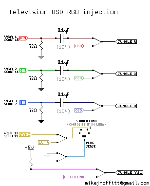
mikejmoffitt wrote:In the OP I made a diagram showing how to do a switched OSD injection.
For the YSW signal, if you are using SCART, you might be able to create this logic:
YSW <= OSD_YSW || SCART_5V
You can look into analogue signal switches to use the OSD_YSW to switch between your injected RGB and the original OSD RGB.
mikejmoffitt wrote: With no second RGB / teletext input; injecting using OSD lines:
* Snip-snap the internal OSD RGB signals going into the jungle mixer
* Inject your RGB there instead, with 75 ohm resistors to ground and then a ~0.1uF capacitor in series to the RGB input
* Pull the jungle mixer blanking pin out of circuit, and tie it high (nearby jungle VCC, usually 3.3~5V) to make it always blanking (always showing RGB)
* Put your composite sync signal into an available luma input (or composite if that's all you have)
* Put that noise on a switch so you can change it back and forth
* Enjoy RGB
I found a low cost TV design that fudges the OSD and SCART input together like this. I think it's the best implementation I've seen. Here's the manual http://etim.net.au/temp/forum/DAEWOO%20 ... V%20SM.pdf (see page 64 of the PDF)
You need to have a resistor in series with the RGB signals. This is because the new termination resistors (75 ohm) in parallel with the RGB video source (75 ohm) makes a load of 37.5 ohms on the RGB input from the OSD signal's point of view. This Daewoo TV puts 150 ohm resistors in series which lifts the load on the OSD signal. Too little or no series resistance = high loading (attenuation) of the OSD, too much series resistance = poor clamp performance. It's a compromise. 150 ohms looks like a good choice to me. The other important part is the RGB OSD signals must each have diodes in series. This way they are effectively out of the circuit when it's off. This prevents loading of the RGB input. An emitter follower + diode OR circuit combines the fast blanking from SCART with the fast blanking of the OSD.