VGA to RGsB: Sync Signal Problems

The place for all discussion on gaming hardware
Post Reply
SamIAm
Posts: 475
Joined: Thu Mar 03, 2005 1:09 am

VGA to RGsB: Sync Signal Problems

Post by SamIAm »

I want to convert VGA to RGsB without changing sync polarity at the source. Yes, I know that that complicates things greatly, but I need to be able to connect old Japanese PCs which don't have the option to do that.

But why RGsB? First, allow me to introduce the AV Multi input.

Image


This only exists on certain Japanese Sony TVs built from the late 90s to the mid-2000s, and it is an RGB input. In fact, it is exactly the same as the AV-out port on a Playstation console, and the only cable ever released for it has the same male head on both ends. This input can even alternate between RGB and YUV - clearly to accommodate the forced YUV DVD playback of a PS2.

The cool thing is, with a hacked cable, it's perfectly possible to use it as a general console RGB port. I've been doing just that for years.

Now, as you may know, the PS2 outputs RGsB whenever it goes above 240p/480i, and the AV Multi input goes right along with that. While it's happy to accept either c-sync or composite sync through its composite line for any 240p/480i source I've thrown at it, it will not accept it for 480p and above. It has to be RGsB.

Right off the bat, I can tell you that I've connected all the lines and gotten a stable picture from 640x480 VGA coming from my laptop. It should be possible to make this work. The only problem is that there is a low-end green tint across the whole screen. Interestingly, white is still white, but black and anything that would have a low green value is tinted. I would like to fix this.

I've done three main things in my attempt to mix VGA sync signals with green.


1. Mix the signals as-is into green (with resistors)


This wasn't what I tried first, but surprisingly, it works. With potentiometers, I have seen how dialing up the resistance on the sync lines causes the amount of green tint to lessen. However, by the time I get to the point that black becomes black, the picture destabilizes.


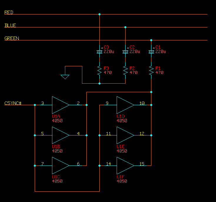
2. Use the circuit on this page to get "c-sync"

Image

The 4070 is a simple XOR gate IC package.

This works, too, but with the same green tint problem.

I could be wrong, but I think the problem with this sync conversion is that it doesn't actually make the positive VGA pulses negative; it makes them inverted positive. On another forum, a guy posted some interesting oscilloscope shots from this very circuit that illustrate this.

Straight VGA H-sync:

Image


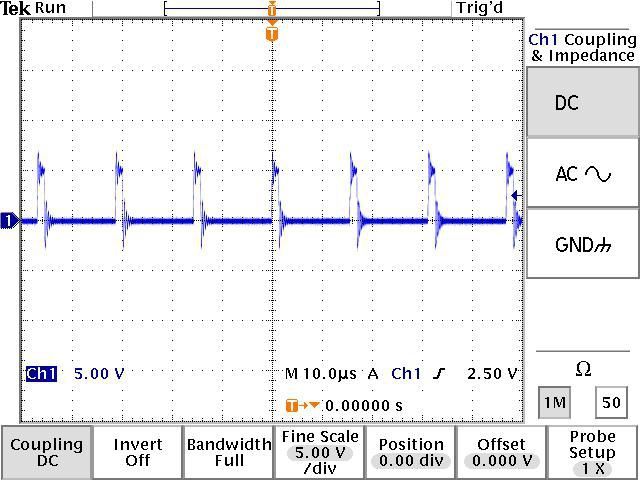
VGA H-sync put through the 4070 as shown above:

Image


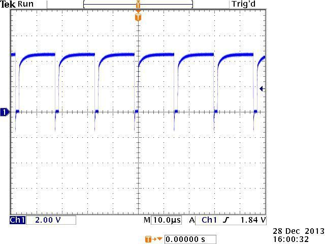
Assuming that PS2 RGsB uses true negative pulses for sync (I wish I had an oscilloscope!), it's easy to see why this wouldn't be what I want.

Why it is that both straight VGA positive sync and this inverted sync cause a similar green tint, I would love to know.

By the way, I also tried putting this into an RGB-YUV converter with the sync on its own line going in, but that simply produced an overall grey tint.

Makes sense.


3. Put VGA sync into an op-amp to generate truly negative pulses.


This did not work at all.

However, I am not an experienced electronics designer, and I might have done something stupid.

What I tried was pretty simple. I connected -5V power to a 741 op-amp, grounded the positive power input and the non-inverting input, and connected the combined VGA sync to the inverting input. Theoretically, that should have resulted in any level of positive pulse on the sync lines producing a -5V negative pulse through the output. I attenuated this with a resistor going into the green signal, which should have also kept the green color information from leaking out.

Again, without an oscilloscope, I can't see what is really happening. With a multimeter, I could verify that putting a constant positive charge on the op-amp's inverting input did result in a negative charge on the output, but that's all.

Interestingly, when I dialed down the resistance going into green, I could see that the entire (scrambled) picture on the screen would tint purple. This would suggest that either the op-amp is very leaky, or that it's constantly outputting negative voltage and actively sucking up the green. It could be that what this needs is a different configuration to make it so it only trips the negative voltage when it should.


4. Tried this circuit from a Japanese website

It's basically #2 but with a transistor in the mix. The green tint remained, and the picture became slightly less stable.

On that page, you can see that that guy there actually had a problem with a purple tint. I have no idea why we are having different results, but it probably has to do with our sources.

Could my laptop be the problem? I've tried two laptops actually, with identical results. Hmm...


So, gents, what do you think? "Buy an Extron", you might say, but where is the adventure in that? I just know I'm a couple of cheap parts away from converting this sync like it needs to be, and if I can pull it off, it would be super-triumphant. Not to mention, I'm in Japan, and that complicates things when trying to get a proper professional converter.

Any ideas? Comments? Thoughts?
Last edited by SamIAm on Sun Nov 27, 2016 9:05 am, edited 6 times in total.
User avatar
Guspaz
Posts: 3242
Joined: Tue Oct 06, 2015 7:37 pm
Location: Montréal, Canada

Re: VGA to RGsB: Sync Signal Problems

Post by Guspaz »

You could use a sync converter. I've got an Extron SC210 that can accept different sync inputs and convert them to different sync outputs. It accepts RGBS, RGsB, RsGsBs, and RGBHV as input. It can output RGBS, RGsB, or RGBHV.

There is one restriction: even though it can handle RGsB, for RGBS it requires clean csync, so you would want to run the input through a sync stripper if using consoels with sync-on-composite or sync-on-luma.

Output sync type can either be detected automatically based on output impedance (three output cables means RGsB, four output cables means RGBS, five output cables means RGBHV), or overridden via dip switches. I believe that a convenient way to switch between RGBS and RGsB would be to connect the csync output to a simple 2:1 BNC switch box like this:

https://www.monoprice.com/product?p_id=1375

With the input sync connected to the switch input, switch output A connected to the display, and switch output B disconnected. That way, setting the switch to position A would cause the SC210 to trigger RGBS, and switch position B would trigger RGsB.

Of course, this is all probably overkill, and the SC210 and its cabling is kind of bulky. It does have the added benefit, however, of stabilizing problematic or out-of-spec sync signals.
SamIAm
Posts: 475
Joined: Thu Mar 03, 2005 1:09 am

Re: VGA to RGsB: Sync Signal Problems

Post by SamIAm »

If I could ship an Extron to Japan for cheap, or if I could find an acceptable local substitute, I would. As it stands, though, buying a couple more 100 yen parts from the local electronics shop would be much easier on the ol' budget. :mrgreen:
User avatar
Unseen
Posts: 738
Joined: Sun May 25, 2014 8:12 pm
Contact:

Re: VGA to RGsB: Sync Signal Problems

Post by Unseen »

SamIAm wrote:I could be wrong, but I think the problem with this sync conversion is that it doesn't actually make the positive VGA pulses negative; it makes them inverted positive.
VGA sync lines are TTL, i.e. the signals are always between 0 and 5V. What you call "inverted positive" is what is meant by "negative sync" - the leading edge of the sync pulse is a negative edge, also known as a falling edge. If you send voltages negative relative to the ground pin over the sync lines, you might damage the circuit in the monitor.
SamIAm
Posts: 475
Joined: Thu Mar 03, 2005 1:09 am

Re: VGA to RGsB: Sync Signal Problems

Post by SamIAm »

Well, if I'm wrong, I'm wrong, and I'll be glad to know that, but my googling told me that NTSC sync pulses were actually negative.

https://www.maximintegrated.com/en/app- ... vp/id/1184

This says the standard is -286mV.

Like this, from another site:

Image
(EDIT: Found a better pic)

If you google oscilloscope shots, it looks like the sync pulses are in true negative range, too.

Just to be clear, this is a TV, and not some kind of computer monitor that only accepts "inverted positive" negative sync on the green line or anything. Given that the PS2's RGsB and YUV can instantly switch between each other on the same lines, I'm willing to bet that this AV Multi input is looking for sync on the green line very similar to what you would see in a typical luminance signal.

And just to be extra sure, I just now booted a PS2 game in progressive 480p mode through this input, and it worked fine.
User avatar
Fudoh
Posts: 13044
Joined: Mon Mar 06, 2006 3:29 am
Location: Germany
Contact:

Re: VGA to RGsB: Sync Signal Problems

Post by Fudoh »

And just to be extra sure, I just now booted a PS2 game in progressive 480p mode through this input, and it worked fine.
and this works with the PS2 set to either YPbPr or RGB in the config menu ?
SamIAm
Posts: 475
Joined: Thu Mar 03, 2005 1:09 am

Re: VGA to RGsB: Sync Signal Problems

Post by SamIAm »

Fudoh wrote:
And just to be extra sure, I just now booted a PS2 game in progressive 480p mode through this input, and it worked fine.
and this works with the PS2 set to either YPbPr or RGB in the config menu ?
Affirmative.

Although you do have to press a button on the TV remote to get it to change modes. If you don't, you get the screwy colors you would normally expect from mixing up RGB and YUV.

The modes are simply displayed as "AV Multi RGB" and "AV Multi Component".

EDIT: This is the VMC-AVM250, the only official cable ever released for the this input.

Image
User avatar
Unseen
Posts: 738
Joined: Sun May 25, 2014 8:12 pm
Contact:

Re: VGA to RGsB: Sync Signal Problems

Post by Unseen »

SamIAm wrote:Well, if I'm wrong, I'm wrong, and I'll be glad to know that, but my googling told me that NTSC sync pulses were actually negative.
Yes, for NTSC. The V+H-Sync to CSync circuit you found is for VGA and similar computer video standards though. IIRC with sync-on-green they commonly use 0V for the sync tip and a 0.3V black level offset for the green video signal.

It's not that clear for NTSC video either though - these signals are almost always AC-coupled, so the display needs to clamp the signal to some reference point internally anyway and the net result is that feeding in a signal with blanking at 0V and -286mV sync tips or a signal with 0V sync tips and blanking at 286mV gives the same picture.
And just to be extra sure, I just now booted a PS2 game in progressive 480p mode through this input, and it worked fine.
Maybe you should just connect a scope while doing this and check that the actual output of the PS2 looks like? I wouldn't be surprised if it's sync tip at 0V and blanking at about 300mV, because that can be generated without a negative supply voltage.
ahaddow
Posts: 36
Joined: Thu Oct 20, 2016 12:13 am

Re: VGA to RGsB: Sync Signal Problems

Post by ahaddow »

I have nothing helpful to contribute other than the fact that I use the VMC-AVM250 and AV multi input on my 27" Wega for PS2 and it does indeed do 480i RGB and 480p YPbPr. It's really helpful having the button on the remote to switch between these modes as well.

Good to know there are others here who live in Japan, SamIAm. I've been here a few years and just started putting together my retro set up recently. I'm down in Nagasaki for what it's worth. How about you?
SamIAm
Posts: 475
Joined: Thu Mar 03, 2005 1:09 am

Re: VGA to RGsB: Sync Signal Problems

Post by SamIAm »

Unseen wrote:Yes, for NTSC. The V+H-Sync to CSync circuit you found is for VGA and similar computer video standards though. IIRC with sync-on-green they commonly use 0V for the sync tip and a 0.3V black level offset for the green video signal.

It's not that clear for NTSC video either though - these signals are almost always AC-coupled, so the display needs to clamp the signal to some reference point internally anyway and the net result is that feeding in a signal with blanking at 0V and -286mV sync tips or a signal with 0V sync tips and blanking at 286mV gives the same picture.
This has all been quite the journey for me.

When I started messing with this a couple of weeks ago, I didn't know much about logic gates. I just looked for a circuit that would change VGA sync to something TV compatible, and followed whatever I found.

Unless I'm mistaken, "C-sync" is supposed to mean the pure form of TV sync. If that's true, then that schematic is misleading. There are others very much like it that claim to output "C-sync" as well. However, I wouldn't be surprised if it actually did work on TVs with a separate line for sync, perhaps with just a resistor to bring the voltage down from the +5V that the 4070 outputs.

I also didn't know about VGA "negative sync" actually being inverted positive and not real negative voltage until just now.

My theory about why the green tint exists, then, is that my laptops are actually outputting VGA negative sync. When I take sync off and look at the scrambled picture, the green tint is gone. When I put it back on and the picture stabilizes, the tint is uniform, and this would make sense if the sync voltage was always "on" except for when it needs to...you know...sync.

This would also explain why I get the same green tint from putting VGA sync through the 4070 as I do just directly slapping it on, and possibly why my op amp idea didn't work at all.
Maybe you should just connect a scope while doing this and check that the actual output of the PS2 looks like? I wouldn't be surprised if it's sync tip at 0V and blanking at about 300mV, because that can be generated without a negative supply voltage.
Like I said above, I don't have an oscilloscope. Maybe I should get one, but before I invest, I wanted to see if anyone here has fought a battle like this before.

What you say about blanking at 300mV makes sense, but note that the red and blue colors all look completely balanced. If the TV were blanking all of the signals at 300mV, I would expect them to be off.

My best guess at the moment is that the blanking is at 0V and I need to generate true negative sync pulses. I think I should just be able to put that "C-sync" circuit back in place, but not put 5V on the final gate (pin 12), and thereby get VGA positive sync to feed into the op amp.

I suppose it's possible that the TV is expecting the green line only to blank at 300mV, but I can test that later.

If someone can google an image of luminance from a console being put through an oscilloscope, I'd love to see it. I can't find anything yet.
ahaddow wrote:I have nothing helpful to contribute other than the fact that I use the VMC-AVM250 and AV multi input on my 27" Wega for PS2 and it does indeed do 480i RGB and 480p YPbPr. It's really helpful having the button on the remote to switch between these modes as well.

Good to know there are others here who live in Japan, SamIAm. I've been here a few years and just started putting together my retro set up recently. I'm down in Nagasaki for what it's worth. How about you?
That AV Multi port is the funniest thing. It's on literally dozens of Japanese consumer Sony TVs from the period, but I'm willing to bet that 99% of people didn't really even know what it was. That cable is quite uncommon as a result.

You ought to try making an adapter cable and connecting that input up to Euro-SCART or Japanese RGB21, then running all of your consoles through it. I've tried SNES, Genesis, Saturn, Dreamcast, MSX, a modded Duo, and a PS1 through this, and they all work.

I'm in Fukuoka city, by the way. You should swing by the Mandarake before their retro game supply dwindles down much further.
User avatar
buttersoft
Posts: 377
Joined: Sun Jul 24, 2016 7:49 am

Re: VGA to RGsB: Sync Signal Problems

Post by buttersoft »

There's another circuit you might try here - https://web.archive.org/web/20070403130 ... ync_r.html
You might even try the steps below with it, if you have a problem.

This next option probably isn't so great but...ATM, if you put your DC meter on the green output you're feeding to the set, or even on the C-sync you've mixed up, what does it show? ~4.7V? Or anything above about 1V? If so, what happens if you put a cap in the sync circuit right before it mixes with green, +ve leg toward the source? I'm not sure about the value you'd want, so try low first (0.1uF) and go up from there. By the time you hit about 100uF, if nothing has changed nothing is going to. Same if the first attempts at low values don't give a picture at all.

I say it's not so great as while it might minimise the DC voltage from the sync line, it's not going to push it negative. It might reduce the problem but I don't think it will fix it. The attrition will probably be too great. Still, it might be worth a shot. The Green video information isn't moving down the line at the same time as the sync, they're separate in time, one after the other, so lowering the DC 'average' the set is seeing might help. Might help the edges of those curves drop faster.

For another option, most sets are pretty generous about what they'll take for composite sync. Your set included, because it *is* finding sync without difficulty. Might be the AC coupling, but either way it works. I realise sync has to be on the green line here, hence the voltage issue AFAIC but for VGA-to-RGBS I've used a simple 1K resistor in the H-sync line, and anything from 1- to about 3.3K in the vertical line. Then just merge the two. Again, you could try the caps above if you have to. (I've used other methods too, like Eviltim's VGA to Jamma Sync circuit, but this one works fine, if you tune the resistor for the V-sync line to minimise interlaced flicker. Not that you need to do that here, but use of diodes might help.) For me, I find different vintages of PVMs like their sync slightly differently, and the best way is to go with a sync circuit you know works on one, and just start adding/removing components like resistors, caps, diodes, to try and lower/modify the voltages where you think you have trouble. You can do some basic calcs, but without knowing the limits of the set you're working with there's often no point. The voltages are low, and if you're playing with a line designed to handle sync you're fine. Just make sure you don't feed +5V to somewhere you shouldn't.

Lastly, you could invest in a Radeon HD card that will output composite sync, and try that mixed in. I'm not sure if all cards still do C-sync though. Or even what level they output C-sync at.

And BTW, Composite sync is just combined H- and V-sync. There are no levels specified for it, when used as a generic term. Different products required different levels, though all consumer TV's worked the same way. That circuit isn't built to deliver C-sync to a consumer TV though :)

EDIT: I reckon you're right about your circuit working with a separate sync line. That wouldn't do anything to the black levels, hence no problem. There'd be a wide range of resistance values it would be happy with too, I'd say.
Last edited by buttersoft on Mon Nov 28, 2016 4:29 am, edited 5 times in total.
ahaddow
Posts: 36
Joined: Thu Oct 20, 2016 12:13 am

Re: VGA to RGsB: Sync Signal Problems

Post by ahaddow »

SamIAm wrote:
That AV Multi port is the funniest thing. It's on literally dozens of Japanese consumer Sony TVs from the period, but I'm willing to bet that 99% of people didn't really even know what it was. That cable is quite uncommon as a result.

You ought to try making an adapter cable and connecting that input up to Euro-SCART or Japanese RGB21, then running all of your consoles through it. I've tried SNES, Genesis, Saturn, Dreamcast, MSX, a modded Duo, and a PS1 through this, and they all work.

I'm in Fukuoka city, by the way. You should swing by the Mandarake before their retro game supply dwindles down much further.
Fukuoka! Wow, you are really close. Yeah I have been up to that Mandarake before but before I really started digging into retro stuff.
I managed to get my AV Multi Cable on Amazon.co.jp used for under 2000 yen, shipped and in box. I was planning to get the AV-Multi -> JP21 adapter and then running my SFC and such through there but I recently scored a PVM-1454Q on Yahoo Auctions for....11 yen. The thing looks better than it has any right to at that price. It needs some tweaking, the image is shifted far to the right but....for 11 yen I am blown away by the relatively good condition this thing is in.
Anyway, so I think I might just do BNC-JP21 on the PVM for SNES and other 15hz stuff, and maybe keep PS2 and PS1 on the AV Multi for now. That could change if I have to move outside of Kyushu though since the 27" Wega is quite a beast...

But anyway, good to know you are close by! Maybe we can help each other out some day.

Hope you get your sync issue resolved.
viletim
Posts: 565
Joined: Mon Aug 07, 2006 6:44 am
Location: Sydney, Australia
Contact:

Re: VGA to RGsB: Sync Signal Problems

Post by viletim »

SamIAm,

Try this.

Image

It only works with direct coupled video (VGA is fine). The output from a CMOS CD4070 is gutless. If you are limited to 1980s tech then you can use a CD4050 (CDxxxx, HEFxxxx, MC14xxxx) to increase drive current. You can use the output of your XOR gate circuit directly if you replace the 4070 with something modern.

Perhaps try without the green video connected first, just red/green. If sync drops when green is connected decrease R1 value. R1 = R2 = R3 because you need to load all three equally to avoid a slight green attenuation.

C1 might be backwards. Use your multimeter to find out.
SamIAm
Posts: 475
Joined: Thu Mar 03, 2005 1:09 am

Re: VGA to RGsB: Sync Signal Problems

Post by SamIAm »

Thank you!

I'll investigate more soon.

Would a 7486 be a better choice over the 4070?
User avatar
buttersoft
Posts: 377
Joined: Sun Jul 24, 2016 7:49 am

Re: VGA to RGsB: Sync Signal Problems

Post by buttersoft »

Thanks for posting, Tim. I would 100% recommend going with what you said above what I said - you actually know what you're doing!
Post Reply