

However, I'm not sure where the blanking signal is. Also, my Micon RGB outs aren't labeled as OSD. Can anyone point me in the right direction? Is this TV not a good candidate? Any help would be greatly appreciated.
Thanks
Mike

roush97 wrote:I've been reading about this RGB mod for a couple weeks now. I'm good with electronics and soldering, but have never messed with a CRT. I could use a little guidance. I'm attempting to add RGB to a JVC AV-27230. My Micon and Jungle IC chips seem nearly identical to KnuckleheadFlow's chips.
However, I'm not sure where the blanking signal is. Also, my Micon RGB outs aren't labeled as OSD. Can anyone point me in the right direction? Is this TV not a good candidate? Any help would be greatly appreciated.
Thanks
Mike

Oh that's nice. I'm worried about my own CRT lust leading to hoarding, but I guess I've got nothing on that.suprcrackers wrote:Houston, I think we have a problem.
If there's diodes behind the point where you add the 5v, they'll keep the electricity from flowing back that way. I had diodes, so I left the original blanking signal intact. It lets a faint ghost of the osd show so I can at least see the volume, input, etc. without having to switch back. It certainly doesn't hurt to disconnect the blanking line though.roush97 wrote: Original blanking signal
Are those terminating resistors before the capacitors? That is this:knohbody wrote: ...wired in the R, G, and B lines with a 0.1 decoupling capacitor and terminated them with a 75 ohm resistor to ground.
Code: Select all
Console RGB out}--------[TV plug]------| C |-----{RGB jungle ic in
                                    |
                                 75 ohm
                                    |
                                   gnd
In the data sheet or the service manual? I don't see anything like that in the data sheet, but maybe there's something in the service manual I missed. Fairly certain my ground is good, I'll give it another check when I get home. I appreciate the second set of eyes.roush97 wrote:knohbody...
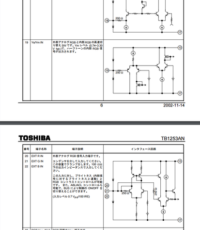
I looked at your data sheet and saw a .1 volt for the RGB pins in. I'm not sure what that means, I'm new to this. Mine were at .7. I will say this though, I had problems for 2 days with my first attempt. Problem ended up being a weak ground.
Dear lord. What do you plan on doing with these when you are done with them?suprcrackers wrote:Houston, I think we have a problem.
Dang, I was hoping it'd be something simple like that.knohbody wrote: KnuckleheadFlow, I do indeed have the resistors before the decoupling caps like in your diagram. My wording may have been a bit off.
Roush97, did you isolate your inputs from the resistors that are already on the OSD? If not, that's probably why your picture is dim.roush97 wrote:Also, my RGB lines from OSD have 4.7 k resistors inline and 1.5 k resistors to ground. Would setting up my RGB input similar to this help?
I forgot to mention, I'm using an ntsc SNES with a scart connector for testing. I have tried that with and without the 220uf caps.
Man that's an annoying service manual to read. On PDF pages 28 and 29 I see pins 61, 62 and 63 on the microprocessor, labeled IC101, sending RGB to 10, 11 and 12 on IC301, which I presume is the jungle IC, on PDF page 13. I don't see any capacitors though and the voltages on those input pins, 0.1v, unfortunately has meant digital RGB in the cases I've seen so far.texaspowtapa wrote:any hope about getting rgb out of this set?
http://www.electronica-pt.com/esquema/f ... down/1623/
roush97 wrote:Knohbody, yes, I did. The .1uf caps were the last thing inline to my jungle IC on the RGB lines. I desoldered those, replaced with 6 wires (3 in from OSD and 3 out to jungle IC. On the 4PDT switch, I soldered .1uf caps inline on each RGB to jungle IC. That way my OSD and my RGB input can both utilize the caps. I have 75 ohm terminations on my RGB lines (terminated to ground on my SCART connector). I also switched my original fast blanking signal (ys) and 5v with the 4PDT switch. It works great except that it is a little dim and shifted to the left a little. Hopefully someone can tell me how to fix it.
Knohbody, I did try switching the component input, but will have to look into game mode. I was also thinking I may need an RGB amp. I have also read about putting a potentiometer on the H AFC input of the Jungle IC to adjust the shift to the left. I will have to play with it some more. Thank you for all your help.knohbody wrote:roush97 wrote:Knohbody, yes, I did. The .1uf caps were the last thing inline to my jungle IC on the RGB lines. I desoldered those, replaced with 6 wires (3 in from OSD and 3 out to jungle IC. On the 4PDT switch, I soldered .1uf caps inline on each RGB to jungle IC. That way my OSD and my RGB input can both utilize the caps. I have 75 ohm terminations on my RGB lines (terminated to ground on my SCART connector). I also switched my original fast blanking signal (ys) and 5v with the 4PDT switch. It works great except that it is a little dim and shifted to the left a little. Hopefully someone can tell me how to fix it.
So, looked at the user manual for that tv ( http://pdfstream.manualsonline.com/3/3f ... cbe32b.pdf ) and saw that there's an option for switching one of the inputs from component to composite.
Might give that a shot and see if it's been changed to component. Also on the spec page for this tv on the jvc site, it says there's a game mode. Some older sets referred to the AV inputs up front as game, but it could also be similar to the newer models where it disables signal post processing. Might try digging through the menus to see if one of those clears up the shift to the left. As for the dimness, maybe a small rgb amp is in order? I'm not sure, just throwing that out there.
I was able to find another small tv for my project that had a more suitable jungle ic. SNES, ps1 and 2 look great. Genesis and master system look horrible, but I think my cable is to blame. Tv is a 13 inch Orion tv1331.
You have the same jungle IC as both my Toshiba and JVC, you most likely do not need an RGB amp. From what I gather, it's needless and only over-complicates the setup, at best.roush97 wrote: .I was also thinking I may need an RGB amp.
