Hello!
My trusty old Sony KVM-1400U has just stopped working. Initally the vertical retrace collapsed, then horizontal seemed to go, then some smoke out of the vents on the back and a burning smell. This was last week, I just tried again and there is no high voltage at all I dont think, I can't hear it, and there's no scan on the screen at all.
I'm experienced with eletronic design and repair, but TV's are not an area I know much about at all.
Any advice on where to start? It feels like this is an "oh, the xxx has failed" situation...
CRT TV Repair
-
mrchief
- Posts: 24
- Joined: Wed Jun 25, 2025 2:42 pm
Re: CRT TV Repair
Start by checking flyback for burn marks.
-
retrogizmo
- Posts: 32
- Joined: Thu Jun 29, 2017 10:29 am
Re: CRT TV Repair
I had a look over the board, I cant see any obvious burn marks. It's pretty grimy around this area. I blew all the dust out a week or two ago looking for an issue with intermittent sync, but this area is a bit "sticky".
The sync trace had actually worn through the resist where the pcb mounts in the case, but didn't appear to be broken, however after attempting to tidy and flow some solder over this trace the sync issue largely resolved. Not sure if my cleaning out the dust caused any issue, seems unlikely, but the timing is coincidental.

The sync trace had actually worn through the resist where the pcb mounts in the case, but didn't appear to be broken, however after attempting to tidy and flow some solder over this trace the sync issue largely resolved. Not sure if my cleaning out the dust caused any issue, seems unlikely, but the timing is coincidental.
-
MKL
- Posts: 453
- Joined: Wed Feb 02, 2005 9:33 pm
- Location: Pordenone, Italy
Re: CRT TV Repair
The +B line (120V) that supplies the flyback transformer T802 is probably missing. You can check it on the jumper JW165 near the big electrolytic cap C609 in the pic above or on R801 in between the small H drive transformer T801 and the flyback. It is generated at the cathode of D604/+ of C609 but those points are harder to reach and it goes to pin 4 of the flyback but there's a kind of fuse in series with it, PS801 (just above R801). Check if it's intact or open. Make sure you're using a valid secondary ground point for measuring this voltage like the metal body of T801 if it's clean or the anode of D802.
-
retrogizmo
- Posts: 32
- Joined: Thu Jun 29, 2017 10:29 am
Re: CRT TV Repair
Thanks for the advice, that's really helpful! PS801 measures about 130K. I need to do a bit of reading on safety for poking about with things turned before doing any live measurements.
Oddly I can't see any burn marks anywhere. I was expecting to see something burnt -- I guess it might be more difficult to see with the amount of grime on theboard in this section.
Oddly I can't see any burn marks anywhere. I was expecting to see something burnt -- I guess it might be more difficult to see with the amount of grime on theboard in this section.
-
MKL
- Posts: 453
- Joined: Wed Feb 02, 2005 9:33 pm
- Location: Pordenone, Italy
Re: CRT TV Repair
In the above pic, the area where PS801 is located (just below the white component) looks blackened. Is it not charred? Maybe it's just dirt. In any case, PS801 which is a ICP-N15 should have a very low resistance (0.135 ohm) so if it measures high ohm something must have happened to it...
Before doing what I suggested above, you could check the resistance to ground of the +B line before and especially after PS801. So, with PS801 off circuit, measure the resistance across the middle leg of Q802 (the horizontal output transistor) and ground (e.g. the leg of Q802 farther away from the flyback). If it's very low, the transistor is probably shorted (further test after removing it from the circuit) which caused PS801 to open (or almost).
Before doing what I suggested above, you could check the resistance to ground of the +B line before and especially after PS801. So, with PS801 off circuit, measure the resistance across the middle leg of Q802 (the horizontal output transistor) and ground (e.g. the leg of Q802 farther away from the flyback). If it's very low, the transistor is probably shorted (further test after removing it from the circuit) which caused PS801 to open (or almost).
-
retrogizmo
- Posts: 32
- Joined: Thu Jun 29, 2017 10:29 am
Re: CRT TV Repair
With PS801 out of circuit it's open. So, yes, that's blown! And I've just given the area a cleanup to see if it's grime or charring, and you're right, it defintely looks charred around R802, C802, C803. R802 looks in pretty bad shape, but is measuring 10K, which is correct going by the parts list.
Resistance of Q802 (IC802 on the silkscreen, but it looks like a power fet of some kind) middle to ground (pin 1 in the pic below) is about 4Mohm, the other leg about 240ohm.
Edit: looking at a better scan of the service manual I spotted Q802, I couldn’t see it before. That measures about 120KOhm from collector to emitter and also collector to base.
Last edited by retrogizmo on Tue Aug 26, 2025 7:40 pm, edited 3 times in total.
-
retrogizmo
- Posts: 32
- Joined: Thu Jun 29, 2017 10:29 am
Re: CRT TV Repair
Unlreated I think, but one of the pins on the flyback is only half soldered!

-
MKL
- Posts: 453
- Joined: Wed Feb 02, 2005 9:33 pm
- Location: Pordenone, Italy
Re: CRT TV Repair
120K isn't particularly low. Just to be clear, do you read the same resistance across pin 4 and 11 of the flyback?
You could desolder Q802 and test it out of circuit. It's a BU508A so an NPN transistor. With meter in diode test mode, red probe on B and black probe on C should give a reading around 0.5V. Red probe on B and black probe on E should give a similar reading just a bit higher. Reverse probes = OL (or whatever it displays when the probes are not touching anything. And always OL on C-E or E-C.
A light bulb test would be useful but I don't know if you have the necessary parts or even want to do it.
Pin 2 of the flyback (supply voltage for the heater/filament in the CRT neck) may need a touch up but it's at least partly soldered to the pad.
-
retrogizmo
- Posts: 32
- Joined: Thu Jun 29, 2017 10:29 am
Re: CRT TV Repair
Yes, I get the same reading between 4 and 11 of the flyback.
With Q802 off the board in diode test --
+ve B
0.455V BC
0.511V BE
-ve B
0L BC
0L BE
CE either polarity 0L
So that's OK by the looks of it. HOT is now back on the board and the flyback pin reflowed. I'll look for some ICP-N15 -- edit: ordered 4, should be with me in a few days.
I should have the bits for a series lightbulb, apart from an incandescent bulb, which I guess you can still pick up easily enough.
Again, many thanks for the help! Nothing like learning by doing things with guidance.
-
MKL
- Posts: 453
- Joined: Wed Feb 02, 2005 9:33 pm
- Location: Pordenone, Italy
Re: CRT TV Repair
Yes, the HOT is good.
Anyway, this kind of current protector isn't a common fixture on Sony TVs or CRT chassis in general. For instance, the KV-M14A which is very similar (BE-4 chassis) doesn't have it on the +B line but the other two voltages (8V and 18V) from the power supply have it.
The question remains as to what caused the protector to blow/open. If the HOT is good and other parts tied to the +B/HOT collector line aren't shorted to ground either, I can think of two things:
1) The +B line also supplies the horizontal drive transformer T801 through R801. If the transformer is faulty, I'd expect R801 to open (it's a fusible resistor designed to do that) before the protector does. But the other way round (protector blown, resistor safe) cannot be excluded. The integrity of R801 (1 Kohm) should be verified anyway. I don't consider this very likely though.
2) The primary side of the flyback (the internal winding connecting pin 4 and 5 has some of its turns shorted to themselves. This issue cannot be verified with a multimeter, you need special tools such as a blue ring tester or a horizontal output circuit simulator. This is more likely in my view and the only solution would be to replace the flyback (HR7411 is the replacement made by HR Diemen).
A light bulb test can be done in various ways, depending on where you put the bulb (which acts as a dummy load instead of the horizontal circuit). If the protector is removed and the bulb is connected to the cathode of the +B recifier D604 (and the other contact of the bulb to ground), you can only verify if the power supply is good or not. The meter must be connected to the same (or equivalent) points so you can read the voltage and not just watch the bulb light up. I think this test would be positive in this case.
Another way to do it is to put the protector (a good one) back in circuit or even just a jumper across its pads (or a 1A fuse for safety) and see if the bulb stays on and the +B voltage is the expected 120V or close. The horizontal drive pulse must be removed so the HOT and consequently the flyback will stay off. This can be done by lifting a leg of R801 so that the primary side of T801 will not get voltage.
Here's an example of the latter test on an arcade chassis (Hantarex Polo):
https://postimg.cc/VdPNxcdM
-
retrogizmo
- Posts: 32
- Joined: Thu Jun 29, 2017 10:29 am
Re: CRT TV Repair
R801 is indeed 1K, so that's ok.
If it's pointing toward the flyback, is there even a reasonably cost effective way of getting a replacement? The only supplier I can see is about £90 before postage.
I'm guessing T801 may have better availabilty. Is there any way to verify this with simple measurements?
If it's pointing toward the flyback, is there even a reasonably cost effective way of getting a replacement? The only supplier I can see is about £90 before postage.
I'm guessing T801 may have better availabilty. Is there any way to verify this with simple measurements?
-
MKL
- Posts: 453
- Joined: Wed Feb 02, 2005 9:33 pm
- Location: Pordenone, Italy
Re: CRT TV Repair
If T801 (437-090) were bad I would ship you one as I have collected many over the years (same part used in many different Sony models) but believe me, it's good.
Where are you located btw? Don't want to be nosey, it's just to evaluate the options.
It would be a pity to find out the flyback is good after buying an expensive replacement (not wasted money though as it may be useful one day if this TV matters to you).
So I would do the 2nd bulb test first which wouldn't tell anything about the condition of the flyback but would exclude other things.
https://ziton-electronics.com/produkt/txo-hr7411/
HR7403 looks compatible too:
https://hrdiemen.com/reparation/flyback/scheme/7411
https://hrdiemen.com/reparation/flyback/scheme/7403
-
retrogizmo
- Posts: 32
- Joined: Thu Jun 29, 2017 10:29 am
Re: CRT TV Repair
I'm in the UK, which can limit options a bit these days.  A lot of European spares places wont ship outside the EU. Although Ziton you linked does seem to ship to the UK, and the flyback is certainly cheap!
I will have a look into the bulb testing to eliminate other issues. This CRT really has a nice picture and is used really regularly, so it would be a shame to dump it. I do have other monitors which I need to dig out and test, but this TV is useful as it has RGB as well as composite, etc, whereas anything else I have will just be RGB.
Edit: There's actually a HR7403 on eBay for £25, if that is indeed compatible, I'll grab that.
-
MKL
- Posts: 453
- Joined: Wed Feb 02, 2005 9:33 pm
- Location: Pordenone, Italy
Re: CRT TV Repair
I think it is. Pin 9 on the 7403 is a positive halfwave but it must be a mistake as only a negative halfwave (as on the 7411), if rectified directly, can give +24VDC. And unlike on the 7411, this is on a separate winding (pin 8 and 9) so pin 8, which is on an unused/isolated pad on your TV, needs to be connected to ground (e.g. pin 11). That's it as far as I see it.retrogizmo wrote: ↑Wed Aug 27, 2025 4:17 pm Edit: There's actually a HR7403 on eBay for £25, if that is indeed compatible, I'll grab that.
-
retrogizmo
- Posts: 32
- Joined: Thu Jun 29, 2017 10:29 am
Re: CRT TV Repair
I’ve found a used HR7411 on an Italian site for not too much with postage, that may be the one I get. Still waiting to get a price on postage for the one on the Bulgarian site, not had a reply. The site isn’t very automated.
Would replacing the fly back and fuse and just powering on to test be a bad idea? Ie. is there chance this could damage the new flyback?
I’ll see what I can come up with for a bulb tester in the meantime.
Would replacing the fly back and fuse and just powering on to test be a bad idea? Ie. is there chance this could damage the new flyback?
I’ll see what I can come up with for a bulb tester in the meantime.
-
MKL
- Posts: 453
- Joined: Wed Feb 02, 2005 9:33 pm
- Location: Pordenone, Italy
Re: CRT TV Repair
The flyback replacement was considered because it's not clear what caused the protector to blow (as the most common culprit, the HOT, turned out to be OK). It is generally assumed that if a fuse (or similar protection) blows it's not because it's bad but because something else made it blow. And this is almost always true. But what if just replacing the protector fixes everything? What do you have to lose? The cost of a fuse? So what I would do is put a fuse (on a PCB holder, remotely wired) where the protector was and see what happens. That's assuming you can get fuse/holder easily, better if from a shop in your area and not online. Or you could use the proper part that I've read is on the way to you.
If the fuse or the new protector blows again, the flyback would be the next step. But I would feel bad if that didn't sort things either so I offer to test the flyback if you send it to me (in Italy) and just pay for the shipping. Not sure if this is more cost-efffective than just buying a new flyback though but my offer stands (if you think I'm trustworthy!).
I have the HR tester which can detect faults like the one assumed here (short in the primary side):
https://postimg.cc/WFFfTLfK
-
retrogizmo
- Posts: 32
- Joined: Thu Jun 29, 2017 10:29 am
Re: CRT TV Repair
Ok, tested used flyback ordered! 40 euro from Italy. You have far better TV spares than we do in the UK! 
If this is the issue, I may order a spare new one as well. Used TV's are getting really expensive, and this is quite a nice little set. After using an LCD with upscaler for a while as a temporary replacement, I'm absolutely hating it.
And thanks again for all your help so far. I'll get to the bottom of this, and if any spares I buy don't end up being the issue, I'll have them for the future. I like having a CRT to hand.
-
Sorny
- Posts: 6
- Joined: Sat Jan 04, 2025 7:07 pm
Re: CRT TV Repair
Hi all, I have a Sony KX-21HV1S (similar to PVM-2730QM) that won't turn on. It will go into standby mode but no picture will show. Well, eventually there is a chance it'll show a picture if I turn it on and off for awhile. Any ideas as to what could be causing it?
-
retrogizmo
- Posts: 32
- Joined: Thu Jun 29, 2017 10:29 am
Re: CRT TV Repair
Finally the new (old) flyback arrived last week, I'll try replacing it when I get a chance, hopefully in a day or two! Fingers crossed.retrogizmo wrote: ↑Sat Aug 30, 2025 1:15 pm Ok, tested used flyback ordered! 40 euro from Italy. You have far better TV spares than we do in the UK!
-
retrogizmo
- Posts: 32
- Joined: Thu Jun 29, 2017 10:29 am
Re: CRT TV Repair
Nice looking monitor! Do you hear the high voltage whine / get static when you turn it on?Sorny wrote: ↑Sat Sep 13, 2025 4:58 am Hi all, I have a Sony KX-21HV1S (similar to PVM-2730QM) that won't turn on. It will go into standby mode but no picture will show. Well, eventually there is a chance it'll show a picture if I turn it on and off for awhile. Any ideas as to what could be causing it?
-
retrogizmo
- Posts: 32
- Joined: Thu Jun 29, 2017 10:29 am
Re: CRT TV Repair
I've (finally) just had a look at the new (old) flyback I got as a replacement, and it doesn't look quite the same.
Checking the part number in the service manual it is 1-439-432-11 which actually seems to be a HR7416 not HR7411. Is this a compatible part or have I got the wrong flyback?
Checking the part number in the service manual it is 1-439-432-11 which actually seems to be a HR7416 not HR7411. Is this a compatible part or have I got the wrong flyback?
-
MKL
- Posts: 453
- Joined: Wed Feb 02, 2005 9:33 pm
- Location: Pordenone, Italy
Re: CRT TV Repair
So you got a 7411 but now you think it's not the correct replacement and you should use a 7416 instead?
That part number corresponds to HR7411:
https://hrdiemen.com/search/index?utf8= ... =143943211
Schematics and board layout confirm that 7411 is correct:
https://postimg.cc/rRTcg2s0
But if something doesn't convince you, I'm all ears.
That part number corresponds to HR7411:
https://hrdiemen.com/search/index?utf8= ... =143943211
Schematics and board layout confirm that 7411 is correct:
https://postimg.cc/rRTcg2s0
But if something doesn't convince you, I'm all ears.
-
retrogizmo
- Posts: 32
- Joined: Thu Jun 29, 2017 10:29 am
Re: CRT TV Repair
Huh, you are right, it does seem to say 7411 on the net for that part number. I'm not sure where I found HR7416 now, I think I seached google and it actually gave me a match with the wrong Sony part number which matched the 7416.
Visusally the two look different, though, which is why I started double checking and then confused myself.
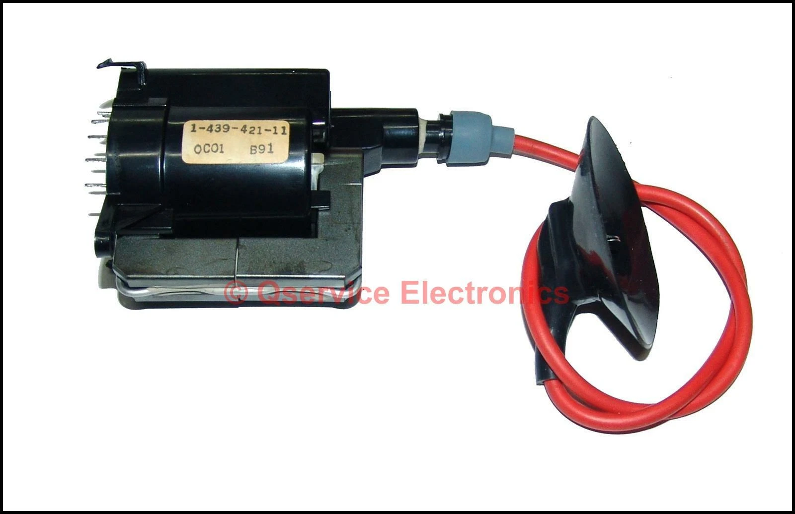
This is what the flyback on the TV looks like --
https://i.ebayimg.com/images/g/k5AAAOSw ... l1600.webp
And the replaement I have is --
https://i.postimg.cc/vZHDgkkJ/image0.jpg
The cup for the HV connector is quite a bit smaller and it's missing a metal C clip type thing on the flyback as well as the plastic case missing a mounting pin. But otherwise it looks the right footprint. I see elsewhere saying 1-439-432-11 was replaced by HR7411. So I guess the sony part 1-439-432-11 is equivilent to HR7411 but not idential?
I'm a bit happier I did actually get the right part now.
Visusally the two look different, though, which is why I started double checking and then confused myself.
This is what the flyback on the TV looks like --
https://i.ebayimg.com/images/g/k5AAAOSw ... l1600.webp
And the replaement I have is --
https://i.postimg.cc/vZHDgkkJ/image0.jpg
The cup for the HV connector is quite a bit smaller and it's missing a metal C clip type thing on the flyback as well as the plastic case missing a mounting pin. But otherwise it looks the right footprint. I see elsewhere saying 1-439-432-11 was replaced by HR7411. So I guess the sony part 1-439-432-11 is equivilent to HR7411 but not idential?
I'm a bit happier I did actually get the right part now.
-
MKL
- Posts: 453
- Joined: Wed Feb 02, 2005 9:33 pm
- Location: Pordenone, Italy
Re: CRT TV Repair
HR replacements aren't 100% identical to the original flybacks. The little, non-electrical, details you mention are normal. I can't see from the pic you posted if that's a genuine HR flyback though. The manufacturer's name and the model number should be engraved in the plastic on the side.
-
Sorny
- Posts: 6
- Joined: Sat Jan 04, 2025 7:07 pm
Re: CRT TV Repair
I agreeretrogizmo wrote: ↑Mon Sep 15, 2025 8:14 amNice looking monitor! Do you hear the high voltage whine / get static when you turn it on?Sorny wrote: ↑Sat Sep 13, 2025 4:58 am Hi all, I have a Sony KX-21HV1S (similar to PVM-2730QM) that won't turn on. It will go into standby mode but no picture will show. Well, eventually there is a chance it'll show a picture if I turn it on and off for awhile. Any ideas as to what could be causing it?
-
retrogizmo
- Posts: 32
- Joined: Thu Jun 29, 2017 10:29 am
Re: CRT TV Repair
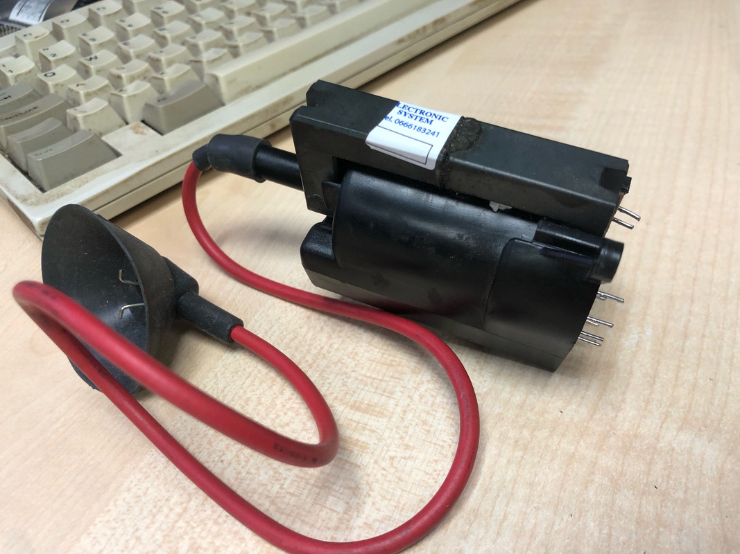
I'm finally back again! I swapped the flyback a few weeks ago but got a bit dispondant when it didn't seem to help. I've actually been a bit more thorough today to see what the replaement has done to the symptoms.
So, I get get some high frequency noise now, but I can't feel any static on the screen or hear the crackle when the TV powers on. Likewise you can hear the high frequency turn off when you power down. I wasn't getting any of this before. So it's done something.
The anode cap fixing is different between the original unit and the replacement. The original used a spade type flat metal connector while the replacement uses two metal spring type arms which hook into the tube. No idea if this has any relevance.
I've just cleaned and checked inside the anode cap socket on the tube, all looks fine, re-seated the anode cap. No difference. So I guess we have deflection now (which I assume is what I can hear) but no HV?
I've also now just gone back and re-read the first few posts. I've checked the voltage at R801 (large resistor between T801 and flyback) and it seems to be reading -0.4V, so yes, no +B voltage.
More digging. At TP +B on the underside of the PCB (I was looking at the silscreen in the service manual and spotted it) I get 125V.
And tracing it through again to see where +B stops, PS801 has blown again! So it wasn't (or wasn't alone if there was an issue) the flyback. Weirdly, I could have sworn I didn't hear the high pitched whine I am hearing now, but I must be mistaken. R801 still intact and 1K. R816 seems ok as does C818 (not short or open anyway). R813 is ok.
-
MKL
- Posts: 453
- Joined: Wed Feb 02, 2005 9:33 pm
- Location: Pordenone, Italy
Re: CRT TV Repair
If you want to make progress you need to do the bulb test (i.e. test the power supply) as described above.
First do it at the cathode of D604 with PS801 off. If you have 120V there, put a wire jumper in the PS801 location and suck solder off pin 4 of the flyback (i.e. pin no longer in contact with surrounding pad) and repeat the test (bulb and meter still connected to D604).
If this kind of test is not your thing, I would say that you need to send it out to a TV repair guy. But the few that are still active are mainly in the arcade scene (e.g. gunblade on ukvac) and will probably not accept to work on this chassis because they don't have a tube to test it with.
-
retrogizmo
- Posts: 32
- Joined: Thu Jun 29, 2017 10:29 am
Re: CRT TV Repair
Ok, I will give that a try. I'm getting 125V +B with no load, so I'll try with a bulb dummy load on +B first then go from there.
-
MKL
- Posts: 453
- Joined: Wed Feb 02, 2005 9:33 pm
- Location: Pordenone, Italy
Re: CRT TV Repair
Was that with jumper on PS801 and pin 4 of FBT desoldered? If so, resolder pin 4 and desolder the HOT (Q802) and see if you still have 125V.retrogizmo wrote: ↑Mon Oct 27, 2025 3:38 pm Ok, I will give that a try. I'm getting 125V +B with no load