No Composite Output from Sony CXA1645P IC - please help

The place for all discussion on gaming hardware
Post Reply
asprinwizard
Posts: 4
Joined: Thu Mar 13, 2025 10:15 am

No Composite Output from Sony CXA1645P IC - please help

Post by asprinwizard »

Hi,

I would really appreciate some expertise here. I am trying to convert an RGBHV signal from a GBS-8220 board modified for GBS control, to composite video. The GBS is outputting a 15Khz signal and I am using the sync combiner circuit described here: https://www.retrorgb.com/building-a-pas ... biner.html. I have previously tested this with the RGB lines on an old RGBS monitor and a Scart TV and it displayed perfectly.

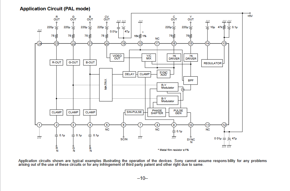
I have followed the example circuit detailed in the datasheet here: https://www.alldatasheet.com/datasheet- ... 1645P.html (PAL version). But the result is no output from the composite pin. Have tested with a oscilloscope and it's a flat line (see screenshot). I have verified the RGB signals and they do register on the oscillioscope - measure around 0.9v with the multimeter on the input pin. Further debugging shows the two vcc pins are both getting 5v, the composite sync signal is around 2.7v. I have a 4.43 MHZ crystal oscillator connected between the SCIN pin (6) and ground. Specifically one of these: https://www.aliexpress.com/item/1005002600232112.html - I think that's the correct setup for PAL.

I have attached photos of everything connected on the breadboard. I appreciate these are not the easiest things to follow but I really don't know how else to show the setup. If anyone has any suggestions please let me know. I'm at a loss as to where to go with this otherwise.

Thanks in advance.

Image
Image
Image
Image

Link to images if they don't show: https://photos.app.goo.gl/GQtkSmPr3zWNtAYGA
User avatar
Syntax
Posts: 1823
Joined: Wed Aug 09, 2017 12:10 am
Location: Australia

Re: No Composite Output from Sony CXA1645P IC - please help

Post by Syntax »

You used a passive crystal, not an oscillator.
Should have 3 active pins, vcc ground and output.

This controls color only I thought though. So really you should at least have a bw pic without it. Might be bigger issues with your setup.

The voltage input to these must be stable and on the mark, if it's low or high you will have rainbows
asprinwizard
Posts: 4
Joined: Thu Mar 13, 2025 10:15 am

Re: No Composite Output from Sony CXA1645P IC - please help

Post by asprinwizard »

Thanks for your reply. I've been away and unable to debug this further as yet but appreciate you taking the time to help. I had thought I'd bought an oscillator but apparently not. In the interests of getting this right, is this what I need? https://www.mouser.co.uk/ProductDetail/ ... IO7g%3D%3D

And do I need any more components on that pin? Resistors or capacitors? I was lead to believe it would just connect straight to ground for PAL but let me know if not.

However as you suggest I suspect something else is the culprit since I would expect to get some kind of output on the composite pin. I have a spare CXA1645 IC so I will test that first to make sure it's not just a bad IC. Anything else you can suggest that might be amiss here?

Thanks in advance
User avatar
Syntax
Posts: 1823
Joined: Wed Aug 09, 2017 12:10 am
Location: Australia

Re: No Composite Output from Sony CXA1645P IC - please help

Post by Syntax »

asprinwizard
Posts: 4
Joined: Thu Mar 13, 2025 10:15 am

Re: No Composite Output from Sony CXA1645P IC - please help

Post by asprinwizard »

Ah that's what I'm looking for. Thanks.
asprinwizard
Posts: 4
Joined: Thu Mar 13, 2025 10:15 am

Re: No Composite Output from Sony CXA1645P IC - please help

Post by asprinwizard »

Hello again. I'm pleased to report some progress with this. The oscillator arrived, as did a replacment IC. It seems it was an issue with the IC. The replacement is giving an output, and I'm getting an image on screen. However it looks rather scrambled. I've attached a screenshot of this. The image is stable (I had missed a ground connection on the sync combiner circuit, but now it's good). I've included the oscilloscope readings for the composite output itself, the crystal oscillator and the sync - in that order.

https://photos.app.goo.gl/wA3EhWdTU8EUBupi8

Here is the schematic I am following:
Image

Does anyone recognise what might be going on here and how I can resolve it. For reference the image on the TV should be colour bars - I would hope that is easy enough to see.

Would really appreciate any advice offered. Thanks.
Post Reply