#######
This thread relates to the original TV RGB Mod thread - http://shmups.system11.org/viewtopic.php?f=6&t=56155
it documents an attempt to mod a TEAC CT-M5122H to allow RGB Scart input
#######
My girlfriend's father had a TEAC CT-M5122H lying around his house that he was happy to be rid of. The TV is in perfect condition. It turns out it is an identical model to one that @buttersoft had attempted to RGB mod but hasn't yet been able to complete.
I'd like to mod this TV so I thought I'd start a thread here to document the process and allow for collaboration.
For starters, here are all the documents I've found so far:
TV Service Manualhttps://drive.google.com/open?id=0BxXDE ... HAyaEJUaVE
TOSHIBA TB1238N Jungle IC datasheet https://drive.google.com/open?id=0BxXDE ... kZxbzJUVGM
TOSHIBA TB1238AN Jungle IC manual - In Chinese unfortunately https://drive.google.com/open?id=0BxXDE ... lNmVjQ4UEU
TOSHIBA TB1240AN Chip very similar to TB1238AN https://drive.google.com/open?id=0BxXDE ... mJybGhZT2s
TOSHIBA TMP87CM38KS-3663 W/CCD & TXT On Screen Display Chip Datasheet https://drive.google.com/open?id=0BxXDE ... FR1aXJGZms
PHILLIPS SAA 5254 Teletext Chip https://drive.google.com/open?id=0BxXDE ... i0xVGlrNTQ (not present in this model but could be helpful)
Z86129/130/131 NTSC 21 Line Decoder https://drive.google.com/open?id=0BxXDE ... GM0NkZVRmc
LA7191N Video Signal Processor https://drive.google.com/open?id=0BxXDE ... VNFZlVnRTA
TC9028 Remote control chip datasheet https://drive.google.com/open?id=0BxXDE ... 2ZnMmtRY1E
TC4053 Mux chip https://drive.google.com/open?id=0BxXDE ... TdWNTZsYm8
User Manual https://drive.google.com/open?id=0BxXDE ... 0JGdGNUZTA
I know a lot of these references aren't necessary but I found them so I thought I'd link them just in case.
RGB OSD TV Mod - TEAC CT-M5122H
-
MarkOZLAD
- Posts: 1040
- Joined: Thu May 18, 2017 12:39 pm
RGB OSD TV Mod - TEAC CT-M5122H
Last edited by MarkOZLAD on Mon Jun 12, 2017 8:46 am, edited 2 times in total.
___________________________________________________
MarkOZLAD
OSD/External RGB Mux Diagram
OSD/External RGB Mux Resistor Value Table 0.7Vp-p : 0.5Vp-p
"Imagine toggle switch OSD modding a TV in 2019" - maxtherabbit
MarkOZLAD
OSD/External RGB Mux Diagram
OSD/External RGB Mux Resistor Value Table 0.7Vp-p : 0.5Vp-p
"Imagine toggle switch OSD modding a TV in 2019" - maxtherabbit
-
MarkOZLAD
- Posts: 1040
- Joined: Thu May 18, 2017 12:39 pm
Re: RGB OSD TV Mod - TEAC CT-M5122H
Ok, so with all the ducks in a row now with regards to documentation...Here are the results of my initial investigations.
I decided not to re-read @buttersoft 's posts prior to my investigations as I wanted to have an open mind. After I finish documenting my ideas here I'll go back and recheck the posts.
Some known things:
1) The Jungle IC requires 0.5V Point to Point Analog RGB signal inputted. Voltage divider required.
2) The Jungle IC will require a voltage of greater than 2.1V blanking signal to take signal from Analog RGB
I noted on the Schematic on the last page of the Service Manual that all RGB and blanking from OSD and/or Teletext goes through a set of Diodes.

It seems a very likely place to inject the RGB and Blanking signal. The diodes are easily found on the top of the chassis.

I am concerned however that there is termination to ground via 1.2k resistors between the diodes and the Jungle. What would be the effect of these? Perhaps the RGB insertion should be at a point after this? Maybe I just go straight into the 0.1 Caps? I was also able to locate those, though they do appear a little delicate, will have to locate which direction they face/which leg to attach to.


Quick question for @buttersoft - Where did you grab ground and voltage for blanking?
I decided not to re-read @buttersoft 's posts prior to my investigations as I wanted to have an open mind. After I finish documenting my ideas here I'll go back and recheck the posts.
Some known things:
1) The Jungle IC requires 0.5V Point to Point Analog RGB signal inputted. Voltage divider required.
2) The Jungle IC will require a voltage of greater than 2.1V blanking signal to take signal from Analog RGB
I noted on the Schematic on the last page of the Service Manual that all RGB and blanking from OSD and/or Teletext goes through a set of Diodes.
It seems a very likely place to inject the RGB and Blanking signal. The diodes are easily found on the top of the chassis.
I am concerned however that there is termination to ground via 1.2k resistors between the diodes and the Jungle. What would be the effect of these? Perhaps the RGB insertion should be at a point after this? Maybe I just go straight into the 0.1 Caps? I was also able to locate those, though they do appear a little delicate, will have to locate which direction they face/which leg to attach to.
Quick question for @buttersoft - Where did you grab ground and voltage for blanking?
___________________________________________________
MarkOZLAD
OSD/External RGB Mux Diagram
OSD/External RGB Mux Resistor Value Table 0.7Vp-p : 0.5Vp-p
"Imagine toggle switch OSD modding a TV in 2019" - maxtherabbit
MarkOZLAD
OSD/External RGB Mux Diagram
OSD/External RGB Mux Resistor Value Table 0.7Vp-p : 0.5Vp-p
"Imagine toggle switch OSD modding a TV in 2019" - maxtherabbit
-
MarkOZLAD
- Posts: 1040
- Joined: Thu May 18, 2017 12:39 pm
Re: RGB OSD TV Mod - TEAC CT-M5122H
Buttersoft, is this why you wanted to get to the service menu for this TV? - to change this bit in the EEPROM?

___________________________________________________
MarkOZLAD
OSD/External RGB Mux Diagram
OSD/External RGB Mux Resistor Value Table 0.7Vp-p : 0.5Vp-p
"Imagine toggle switch OSD modding a TV in 2019" - maxtherabbit
MarkOZLAD
OSD/External RGB Mux Diagram
OSD/External RGB Mux Resistor Value Table 0.7Vp-p : 0.5Vp-p
"Imagine toggle switch OSD modding a TV in 2019" - maxtherabbit
-
MarkOZLAD
- Posts: 1040
- Joined: Thu May 18, 2017 12:39 pm
Re: RGB OSD TV Mod - TEAC CT-M5122H
This entry contradicts that one slightly but means will only need 0.63V to trigger the OSD RGB through the pin 13 and no changes to service menu.

For the record, these are the Bus Control Mappings.

For the record, these are the Bus Control Mappings.
___________________________________________________
MarkOZLAD
OSD/External RGB Mux Diagram
OSD/External RGB Mux Resistor Value Table 0.7Vp-p : 0.5Vp-p
"Imagine toggle switch OSD modding a TV in 2019" - maxtherabbit
MarkOZLAD
OSD/External RGB Mux Diagram
OSD/External RGB Mux Resistor Value Table 0.7Vp-p : 0.5Vp-p
"Imagine toggle switch OSD modding a TV in 2019" - maxtherabbit
-
buttersoft

- Posts: 377
- Joined: Sun Jul 24, 2016 7:49 am
Re: RGB OSD TV Mod - TEAC CT-M5122H
i tend to use the 5V line from whichever source, through a divider if needed. Everything outputs 5V, and you need a common ground for video anyway.
With this set, i'm getting massive noise through the picture. The inputs *must* be enabled, because the OSD uses them, and the OSD is nice and clean... I've tried everything from just above 0V to 5V for the blanking, removed almost all the input-line components in stages, and the best i can do is below. This is where i've hit a wall. All i can think of was something in the service menu, but who knows at this stage.
EDIT: Hmmm, i have had problems with filter caps to ground before. I do wonder if it's some cap causing the problem. But it might not be something i can just remove, anyway.
With this set, i'm getting massive noise through the picture. The inputs *must* be enabled, because the OSD uses them, and the OSD is nice and clean... I've tried everything from just above 0V to 5V for the blanking, removed almost all the input-line components in stages, and the best i can do is below. This is where i've hit a wall. All i can think of was something in the service menu, but who knows at this stage.
Also, having the EEPROM mapping for the set hasn't helped me. I've dumped three different EEPROMs from three different sets, and the results are intransigent. If I had to guess, I'd say in most cases either the Micom reads the EEPROM but feeds the jungle chip as a separate process, or, of course, i'm an idiot who can't read properly. About 50/50, really.So i'm having a problem with the chassis from a Teac CT-M5122H. The RGB is connected through IC101 pins 14-16, with pin 13 as blanking. It works fine, i haven't yet adjusted the levels, but the interference in the picture is really, really bad. I've tried disconnecting the OSD at R635-R638, reconnecting it, and a few other things. The picture is crawling with grey, almost horizontal lines that bow a bit in the middle. Removing R655-R658 seems to make the problem worse.
(Note that the service manual contains a mistake - pin 16 of IC101 is not connected to the blanking line near R655-R658)
EDIT: I really need to try taking the input caps right out of circuit so nothing from the filter caps near the missing ICs 801 & 802 can interfere...? I'll try it and report back.
...Nope. Made the noise problem far, far worse. I'm going to have to think about this one, but any help would be much appreciated
EDIT: Hmmm, i have had problems with filter caps to ground before. I do wonder if it's some cap causing the problem. But it might not be something i can just remove, anyway.
-
MarkOZLAD
- Posts: 1040
- Joined: Thu May 18, 2017 12:39 pm
Re: RGB OSD TV Mod - TEAC CT-M5122H
have you tried pumping it directly into the capacitors I mentioned? (C151-153)
When I did the mod of the Trinitron the only components between where I fed the RGB and the jungle were 0.1 caps. That is where I'm focussing on for now.
When I did the mod of the Trinitron the only components between where I fed the RGB and the jungle were 0.1 caps. That is where I'm focussing on for now.
___________________________________________________
MarkOZLAD
OSD/External RGB Mux Diagram
OSD/External RGB Mux Resistor Value Table 0.7Vp-p : 0.5Vp-p
"Imagine toggle switch OSD modding a TV in 2019" - maxtherabbit
MarkOZLAD
OSD/External RGB Mux Diagram
OSD/External RGB Mux Resistor Value Table 0.7Vp-p : 0.5Vp-p
"Imagine toggle switch OSD modding a TV in 2019" - maxtherabbit
-
MarkOZLAD
- Posts: 1040
- Joined: Thu May 18, 2017 12:39 pm
Re: RGB OSD TV Mod - TEAC CT-M5122H
At this point I probably should remind you I'm very new to all this. I'm having trouble identifying a good 5V and ground source (I'm sure I'll find ground if I take another look) for this TV chassis and wondering if you could have a look and see where you attached yours.buttersoft wrote:i tend to use the 5V line from whichever source, through a divider if needed. Everything outputs 5V, and you need a common ground for video anyway.
___________________________________________________
MarkOZLAD
OSD/External RGB Mux Diagram
OSD/External RGB Mux Resistor Value Table 0.7Vp-p : 0.5Vp-p
"Imagine toggle switch OSD modding a TV in 2019" - maxtherabbit
MarkOZLAD
OSD/External RGB Mux Diagram
OSD/External RGB Mux Resistor Value Table 0.7Vp-p : 0.5Vp-p
"Imagine toggle switch OSD modding a TV in 2019" - maxtherabbit
-
buttersoft
- Posts: 377
- Joined: Sun Jul 24, 2016 7:49 am
Re: RGB OSD TV Mod - TEAC CT-M5122H
What's your source? Consoles all output 5V, probably save some weirder older ones, and VGA certainly does, on pin 9. I tend to build my own cables, i just tap 5V by adding a wire to the connector I'm using. Most console connectors are pretty easy to source, you just buy a cheap cable and split the plug carefully. And VGA plugs are easy to come by.MarkOZLAD wrote:At this point I probably should remind you I'm very new to all this. I'm having trouble identifying a good 5V and ground source (I'm sure I'll find ground if I take another look) for this TV chassis and wondering if you could have a look and see where you attached yours.buttersoft wrote:i tend to use the 5V line from whichever source, through a divider if needed. Everything outputs 5V, and you need a common ground for video anyway.
Ground is everywhere on a PCB. Not Earth, that refers to mains earth, and most tv's like this one are two-pin plug, so no earth. Also not neutral, so make sure you're not thinking one line from the mains plug is "safe" in any way, or the same as ground. If you look at your shot of the jungle chip, and the resistors in circuit, that symbol with a short flat line and three smaller lines down at an angle, is ground. The pin of the jungle IC above the blanking line is wired to board ground. The outside of each RCA coax socket (and plug) is at ground - which is the same as saying connected to ground.
There are several other ways to indicate ground. A triangle pointing down like an arrow is one. 0V is another, or the word "com" for common ground too. But this schematic uses the ground plane symbol - the short line with three angled lines under it.
I did try inputting RGB the signal directly to the capacitors, removing the far leg of each so there was nothing else in the circuit. That way produced even more picture noise than anything else.
-
MarkOZLAD
- Posts: 1040
- Joined: Thu May 18, 2017 12:39 pm
Re: RGB OSD TV Mod - TEAC CT-M5122H
Oh so you get the voltage from the attached device? I was under the impression I had to get it from within the tv.
What was the source you were using when modding the Teac?
What was the source you were using when modding the Teac?
___________________________________________________
MarkOZLAD
OSD/External RGB Mux Diagram
OSD/External RGB Mux Resistor Value Table 0.7Vp-p : 0.5Vp-p
"Imagine toggle switch OSD modding a TV in 2019" - maxtherabbit
MarkOZLAD
OSD/External RGB Mux Diagram
OSD/External RGB Mux Resistor Value Table 0.7Vp-p : 0.5Vp-p
"Imagine toggle switch OSD modding a TV in 2019" - maxtherabbit
-
buttersoft
- Posts: 377
- Joined: Sun Jul 24, 2016 7:49 am
Re: RGB OSD TV Mod - TEAC CT-M5122H
I always use my video source to provide the blanking voltage. Functionally it's no different though. But I build a 5v line into all my cables so i can power sync-stripper and amps when I need to.MarkOZLAD wrote:Oh so you get the voltage from the attached device? I was under the impression I had to get it from within the tv.
What was the source you were using when modding the Teac?
I was using a PSOne with the Teac CT-M5122H. I'll reply to that thread on AA about what I think is going on, though.
-
MarkOZLAD
- Posts: 1040
- Joined: Thu May 18, 2017 12:39 pm
Re: RGB OSD TV Mod - TEAC CT-M5122H
Wow, I never finished this thread? Weird, that's not like me....
I was able to successfully mod this TV. I used the OSD Mux method to do the job. Steps are:
1) remove resistors R656, R657 and R658, these are the factory OSD RGB termination resistors
2) There are diodes on the OSD RGB circuits and there are 1000 Ohm resistors inline on the OSD RGB lines. A quick look at the OSD Mux RGB External Inline Resistor Table.jpg says that we should use 160 Ohm resistors as our new external RGB inline resistors
3) Twist one leg of a 160 Ohm resistor to a 75 Ohm resistor. Make a Y shape from the resistors. Do this three times.
4) Solder the three Y shaped Resistor pairs into the holes left by R656, R657 and R658. The leg of the 160 Ohm resistor should be on the "Jungle side", the leg of the ohm to the "Ground" side. We should have the twisted legs sticking up.
5) Solder the external R, G and B lines to the appropriate twisted legs sticking up
6) For blanking there are multiple options. Probably go with the method the 8 Bit Guy came up with, lift the leg of R635 that is closest to the Microcontroller. Install a switch. One side of the switch will go to 5V (the output leg of IC901 5V regulator), the other side of the switch will be connected by a wire to the hole left by the lifted leg of R635, the middle pin of the switch will go to the leg of R635 that we just lifted.
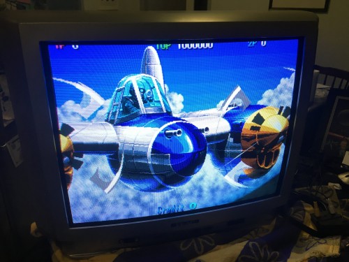
___________________________________________________
MarkOZLAD
OSD/External RGB Mux Diagram
OSD/External RGB Mux Resistor Value Table 0.7Vp-p : 0.5Vp-p
"Imagine toggle switch OSD modding a TV in 2019" - maxtherabbit
MarkOZLAD
OSD/External RGB Mux Diagram
OSD/External RGB Mux Resistor Value Table 0.7Vp-p : 0.5Vp-p
"Imagine toggle switch OSD modding a TV in 2019" - maxtherabbit
-
Greenman
- Posts: 9
- Joined: Wed Sep 14, 2022 6:05 am
Re: RGB OSD TV Mod - TEAC CT-M5122H
Thank you Mark. That is super helpful. If the signal was coming from an arcade PCB (Ms Pacman), rather than a console, would that make a difference to the resistors used?
-
MarkOZLAD
- Posts: 1040
- Joined: Thu May 18, 2017 12:39 pm
Re: RGB OSD TV Mod - TEAC CT-M5122H
If you use arcade pcb you’ll still want to mod the TV in the same way but you will need to add resistors on the JAMMA RGB and sync lines before they reach the tv.Greenman wrote:Thank you Mark. That is super helpful. If the signal was coming from an arcade PCB (Ms Pacman), rather than a console, would that make a difference to the resistors used?
Another option is to buy a supergun that will attenuate the signal for you.
Essentially the mod makes the TV the same as a scart set. You then want to convert Jamma video levels to scart levels.
EDIT: I see you're actually asking about a Ms Pacman. I don't have any experience with that PCB. I have used Wonderboy and NBA Jam PCBs though.
___________________________________________________
MarkOZLAD
OSD/External RGB Mux Diagram
OSD/External RGB Mux Resistor Value Table 0.7Vp-p : 0.5Vp-p
"Imagine toggle switch OSD modding a TV in 2019" - maxtherabbit
MarkOZLAD
OSD/External RGB Mux Diagram
OSD/External RGB Mux Resistor Value Table 0.7Vp-p : 0.5Vp-p
"Imagine toggle switch OSD modding a TV in 2019" - maxtherabbit
-
Greenman
- Posts: 9
- Joined: Wed Sep 14, 2022 6:05 am
Re: RGB OSD TV Mod - TEAC CT-M5122H
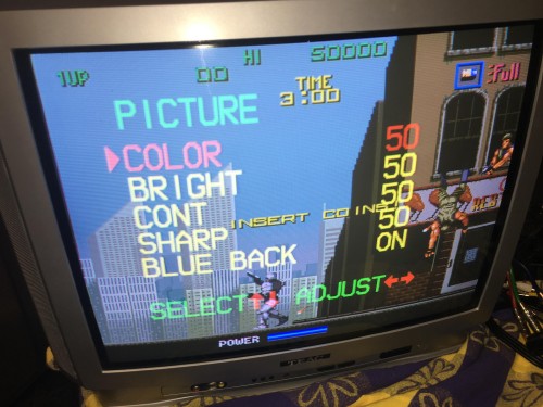
That mod worked perfectly!!
Only issue I am having now is the vertical and horizontal needs adjustment. As I have the same/similar monitor to you, is this able to be achieved using the remote control? If so, I'll buy one.
https://youtu.be/XjWcdB9sFms
Only issue I am having now is the vertical and horizontal needs adjustment. As I have the same/similar monitor to you, is this able to be achieved using the remote control? If so, I'll buy one.
https://youtu.be/XjWcdB9sFms
-
MarkOZLAD
- Posts: 1040
- Joined: Thu May 18, 2017 12:39 pm
Re: RGB OSD TV Mod - TEAC CT-M5122H
The factory remote has a button hidden beneath a small hole. It will launch the service menu.
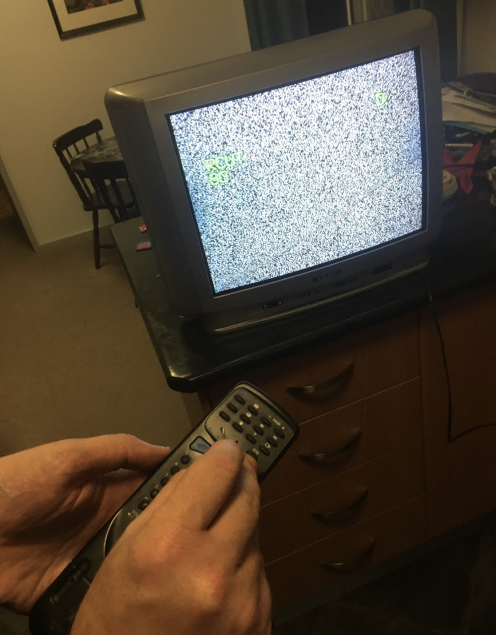
Can’t change horizontal size, only position.
Can’t change horizontal size, only position.
___________________________________________________
MarkOZLAD
OSD/External RGB Mux Diagram
OSD/External RGB Mux Resistor Value Table 0.7Vp-p : 0.5Vp-p
"Imagine toggle switch OSD modding a TV in 2019" - maxtherabbit
MarkOZLAD
OSD/External RGB Mux Diagram
OSD/External RGB Mux Resistor Value Table 0.7Vp-p : 0.5Vp-p
"Imagine toggle switch OSD modding a TV in 2019" - maxtherabbit
-
Greenman
- Posts: 9
- Joined: Wed Sep 14, 2022 6:05 am
Re: RGB OSD TV Mod - TEAC CT-M5122H
Thanks Mark. I think I've found online that exact remote control. Does it change vertical position also?
-
MarkOZLAD
- Posts: 1040
- Joined: Thu May 18, 2017 12:39 pm
Re: RGB OSD TV Mod - TEAC CT-M5122H
From memory, yes.Greenman wrote:Thanks Mark. I think I've found online that exact remote control. Does it change vertical position also?
___________________________________________________
MarkOZLAD
OSD/External RGB Mux Diagram
OSD/External RGB Mux Resistor Value Table 0.7Vp-p : 0.5Vp-p
"Imagine toggle switch OSD modding a TV in 2019" - maxtherabbit
MarkOZLAD
OSD/External RGB Mux Diagram
OSD/External RGB Mux Resistor Value Table 0.7Vp-p : 0.5Vp-p
"Imagine toggle switch OSD modding a TV in 2019" - maxtherabbit
-
Greenman
- Posts: 9
- Joined: Wed Sep 14, 2022 6:05 am
Re: RGB OSD TV Mod - TEAC CT-M5122H
Awesome. Thank you!
-
reminiz
- Posts: 8
- Joined: Mon Feb 24, 2025 11:04 am
Re: RGB OSD TV Mod - TEAC CT-M5122H
Will this same mod work on the CT-M5100?
SM Here:
https://elektrotanya.com/cgi-bin/downlo ... 100_sm.pdf
Cheers!
SM Here:
https://elektrotanya.com/cgi-bin/downlo ... 100_sm.pdf
Cheers!
-
MarkOZLAD
- Posts: 1040
- Joined: Thu May 18, 2017 12:39 pm
Re: RGB OSD TV Mod - TEAC CT-M5122H
Has same jungle chip so modding will be possible.
RGB “grounding” resistors are R267, R268 and R269.
Suggest lifting legs of OSD inlines at R029, R030, R031 and adding 1n4148 diodes. Lift the leg closest to the jungle and solder in diodes with stripe pointing to jungle.
For RGB remove R267, R268 and R269. Use 910 ohm resistors twisted together with 75 ohm resistors. Leg of 75 ohm goes to ground. RGB lines get soldered to the twisted legs.
For blanking, find the output of the 5V regulator, send it through a 1000 ohm resistor to a switch, then from out of the switch run a wire to the leg of R032 that goes to the jungle.
___________________________________________________
MarkOZLAD
OSD/External RGB Mux Diagram
OSD/External RGB Mux Resistor Value Table 0.7Vp-p : 0.5Vp-p
"Imagine toggle switch OSD modding a TV in 2019" - maxtherabbit
MarkOZLAD
OSD/External RGB Mux Diagram
OSD/External RGB Mux Resistor Value Table 0.7Vp-p : 0.5Vp-p
"Imagine toggle switch OSD modding a TV in 2019" - maxtherabbit