Here's a real translation.
--------------
1st page
--------------
When displaying a PCE on a DT-V1910C through RGB, the upper area skews. To deal with this, I didn't use C-sync or signals split from C-sync, but tried connecting the H-sync and V-sync that the console puts out directly.
I learned through a foreign website that the PCE's H-sync and V-sync are output through pins B-11 and A-10 on the expansion connector, but in the case of my Duo-R, there is no connector, and I needed to take the signals from somewhere else.
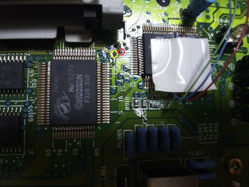
Tracing with my tester (multimeter?), I followed these lines [on my normal PCE] to pin 71 and 72 of the HuC6260, and found that there are test lands between the HuC6260 and the HuC6270. These lands are where I took the signals. In the image, the red circle shows H-sync, and the yellow circle shows V-sync.
(Note: this may be different depending on your version of the board. If you're attempting this, please verify everything with a tester just to be safe)
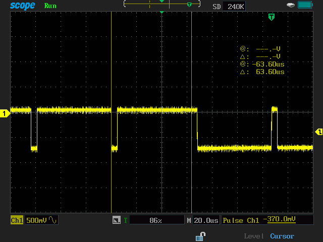
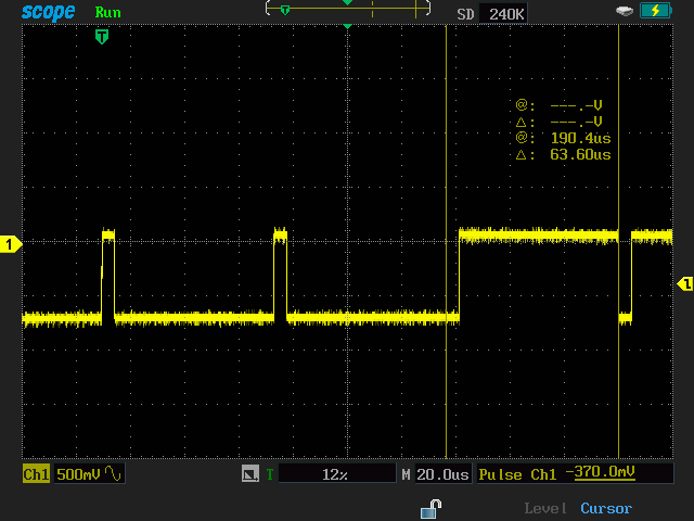
However, both the horizontal and vertical signals as-is on the DT-V1910C are unstable. So, I used 74HC123s to change the pulse width of the H-sync to 4.7uS and the V-sync to 190uS. On a previous occasion, the 4uS width of an AFC HD signal I got with an NJM2257D C-sync splitting circuit gave an unstable picture. By widening the pulses, I fixed the problem; short pulses seem to be a bad thing.
Mixing the resultant signals does cause some skewing like you see in the picture below.
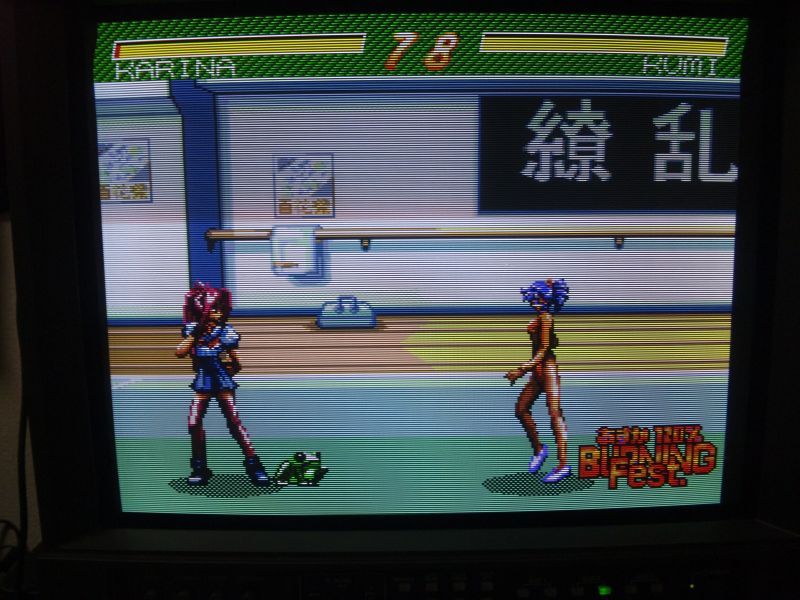
[Translator's note: this is still
vastly improved over what I'm seeing on my Ikegami.]
But, with them separated, the skewing no longer happens.
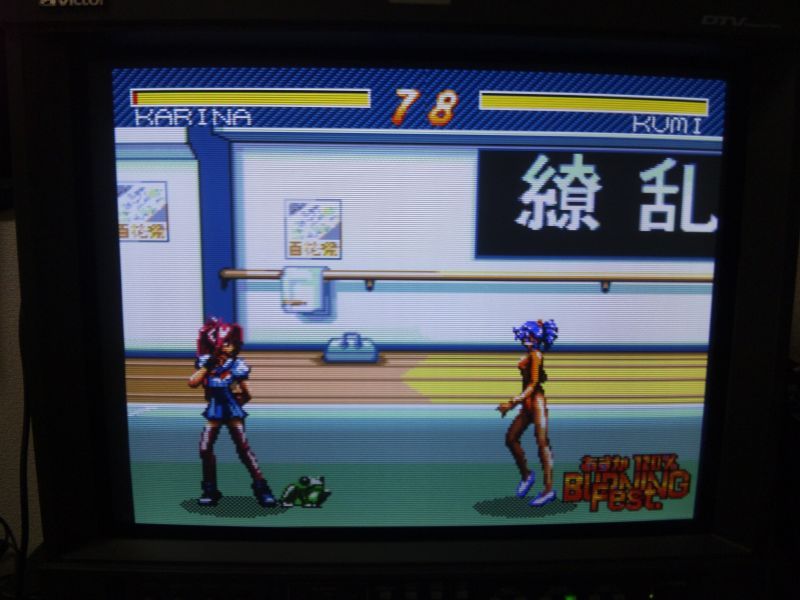
It would seem that I have solved the problem, but bear in mind that the signals I'm taking are supposed to be for internal use, and for this reason the image is shifted more to the right than it would be with C-sync. I think that this is because the H-sync timing is early. Adding a delay through the dot clock should fix it, so I plan on trying a shift resistor as soon as I can get one.
However, besides requiring modding, this approach only works on hardware that has separate sync signals. I don't know what I could do about the Neo Geo...
--------------------------------------------------
--------------
2nd page:
--------------
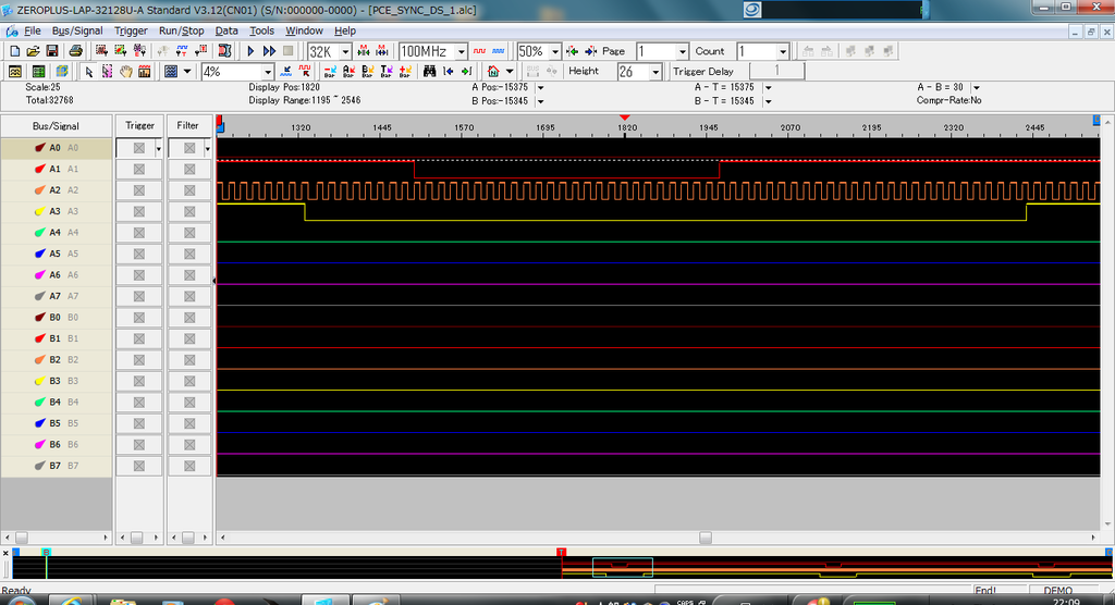
When using the PCE's separate sync signals as-is, the screen shifts to the right. I decided to have a look at the H-sync timing with my logic analyzer. I used Zeroplus's lowest-rung model, the LAP-C(16032). Measurements are from a white PC Engine with a Tennokoe 2.
Because there might be a difference caused by the dot clock, I looked at two games: Dragon Spirit and R-Type. The red line is c-sync split from composite video (I wasn't able to measure internal c-sync because of differences in logic level). The orange line is the dot clock, and the yellow line is the Hu6260's H-sync.
First is Dragon Spirit:
Next is R-Type:
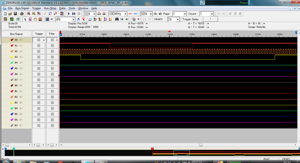
Look at that - it's not synced up with the dot clock! It seems that the C-sync pulses in both games have a delay equivalent to 36 ticks of the main 21.48MHz clock. While it is possible that my sync splitting circuit is adding some extra, there is no mistaking that the added delay is huge. Also, last time, I was saying that the H-sync pulse must be short, but in reality, it's long.
I could try tapping the main clock [to fix the image-shift problem], but making a circuit to add a delay of 36 ticks is a hassle. I decided that basically, I just needed to make the delay the appropriate length, and that this should be possible with 74HC123s. However, these timings being as short as they are, there is a chance that things won't go according to plan and will require adjustments.
I'll put a circuit diagram below. Due to the 74HC123's bender (?) the pulse width timing is off, so please use a TC74HC123. If you use this circuit, don't blame me for anything bad that happens.
*6/26 Note: If you connect this output to the DT-V1910C's H-sync and V-sync lines, the specified current in the ICs will not be enough for 75 ohm impedance. Please do not connect them directly.
*7/1 Note: I updated this to work on the DT-V1910C's sync inputs.
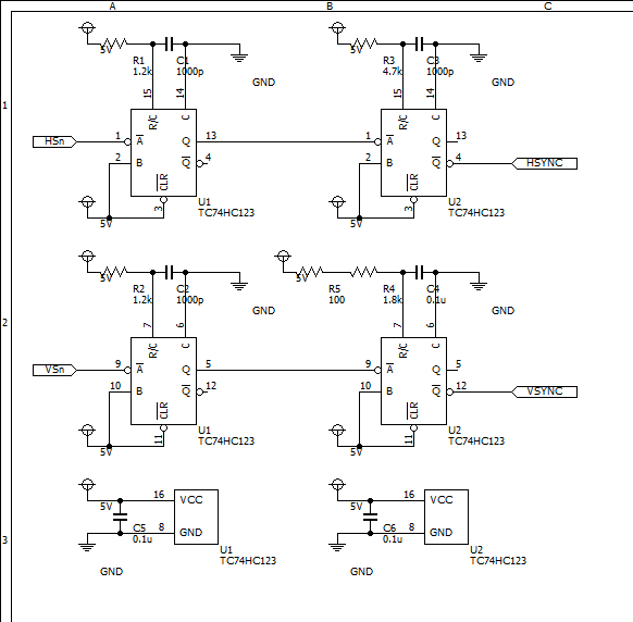
I connected everything like this:
HSn is pin 71 of the HuC6260
VSn is pin 72 of the HuC6260
5V and GND are connected to the same lines as the HuC6260.
I was able to get the sync signals from the test lands mentioned in the last post.
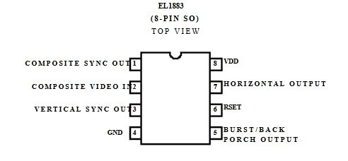
Using this circuit, you will get a picture in roughly the same position as you would if you used an EL1883 to separate H-sync and V-sync, but it will be a little more to the left compared to a SELECTY21. I get the feeling I added too much delay, so it might be a good idea to reduce the values of C1 and C2.
------------------------------------
------------------------------------
I made a couple of goofs in my earlier summaries, but went back and corrected them.
What he doesn't clarify is what happens when you use HV sync from an EL1883, possibly putting them through the same 74HC123 ICs to regulate their pulse widths. If that works, it would be a non-invasive solution for anyone who is using composite video in their RGB mod.
EL1883s are not common here, but I think I can get one. Time for some shopping!