Anyway , feel free to correct me or to coment, thanks for your time.
Service manual: https://diagramas.diagramasde.com/otros ... +video.pdf

wow very nice thanks for drawing this up and taking the time to scanMarkOZLAD wrote:
MarkOZLAD wrote:You need to go and look at the schematic of your set and compare it to my diagram. There’s only so much I can help you….and only so much I’m willing to help.
For the 5V you’ll likely want to find the output pin of the 5V regulator.
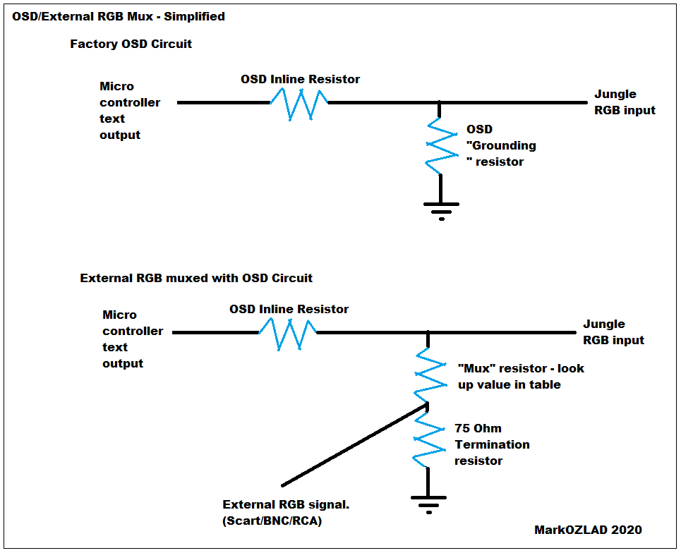
Does this help?abispac wrote:i still dont understand the mux mod.
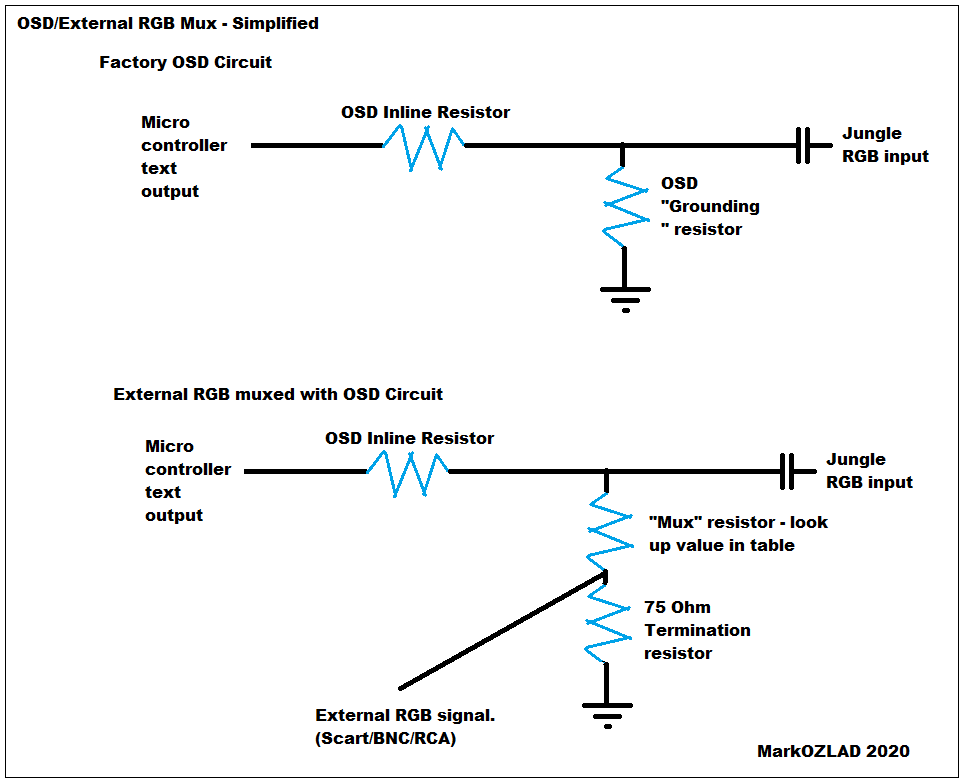
So i was going to say, dont get mad at Markozlad, to anyone, for not wanting to spoon feed you, as he is almost the only one maintaining this topic alive, and i understand, he gets tired of answering the same bull questions over and over. But theres also people like me, that is hard to understand how this mux thing works. chosing where the osd resitor or the ground resistor are is confusing. Thats where the problem starts for fools like me. Now with this new picture, i think it makes it a bit more clear, theres resitors going to ground and resistors that conect to caps, so i get a better understanding on where to input the rgb signal.MarkOZLAD wrote:Does this help?abispac wrote:i still dont understand the mux mod.
Cant agree more, you deserve alot of credits for alot of mods done thanks to the thread. Thanks againg bro. Hope this last mod i dont need to bother you. Im just trynig to figure out if my set has also the closed caption resitor that needs to get bypased. So ill keep searching.MarkOZLAD wrote:abispac…not angry at all, I just thought maybe you missed that new diagram. I think it makes it a bit easier to understand. The other thing that should be understood is the concept of “Voltage Dividers”.
I do sometimes get a bit miffed about having to spoon feed. If people want to mod TVs they need to understand that it takes some work, especially when stuff goes wrong.
Nope, there's no closed caption resistor to worry about on your set. Your set is pretty much the simplest example for a OSD Mux. Just do the twist method on resistors R204, 205 and 206 (if they exist, there's a * next to them on the schematic)abispac wrote:Im just trynig to figure out if my set has also the closed caption resitor that needs to get bypased. So ill keep searching.
Thanks Mark, that makes things easier.MarkOZLAD wrote:All grounds can be connected together and to one point on the chassis.
If I use a manual RGB switch, can I leave SCART pin 16 with no connection? Or do I still need to connect a resistor to provide 75 Ω termination?MarkOZLAD wrote:An automatic switching to RGB could be done using scart pin 16 but you would likely need to make an assumption about how the source device is providing voltage to pin 16. Easier and potentially more reliable to use a switch.
Nope, although I believe you can do an S-Video mod.KPackratt2k wrote:Would it be possible to RGB mod a Sony KV-1380R? I've been negotiating with someone who can fix the convergence problems with my KV-27V20 and he offered to fix it if I could mod his set. Doing a quick Google search, this appears to be a 1987-1990 model, so I have a feeling that it might be too old to have a full-color OSD or a secondary RGB input, in which case I'll likely have to resort to either neckboard modding, or S-Video modding. If you had to choose between just those two, which would be the best?
Thanks, that's exactly what I thought. The same guy also has a Sony KV-20FV10 that can be RGB modded as it has the BA-4C chassis which is pretty much identical to the BA-4D which has been modded multiple times. I told him that the KV-1380R could only be S-Video modded, so maybe I'll do that some other time if he wants.matt wrote:Nope, although I believe you can do an S-Video mod.


Have you tried different consoles to rule out the console?jardelito wrote:Hi there folks,
I have a Sony Trinitron KV-25FV12B (BA-5) and I installed the RGB MOD with OSD Mix.
I changed all the electrolytic capacitors, but I still have a curved (vertical) line on the left side of the screen, which appears in dark images:
I've already reviewed all the modification, cables, wires position, grounding and so far I've had no success.
Does anyone have any idea what might be generating this vertical curved line?
Thanks for any suggestions, as I've been trying for several days.

Thanks! I'll have to check this out on mine! I didn't even pay attention to if it's outputing stereo or mono.KPackratt2k wrote:I have a little PSA to anyone who has RGB modded (or is looking to RGB mod) a Sony AA-2 chassis TV using a SCART connector...
Hopefully this helps anyone who is modding a Sony TV with an AA-2 chassis.


Quoting this ancient thread but I have a direct question for LuckyDay and Pikkon. I plan to mod this 13M42 and have been considering the sync problem. As expected, the composite sync strategy shifts the image to the left which can't be rectified in the service menu. How did you two end up fixing this problem for your sets? Was there another location you wired sync into directly?LuckyDay wrote:Yeah, composite sync is a good inch shifted to the left I believe.Pikkon wrote:Does yours have a horizontal shift when using composite as sync,just tried rf as sync and and pretty much fixed it but don't really want to go to the trouble using that setup.LuckyDay wrote:Otherwise though the rgb mod on the 14" looks great, and I have another set sitting and waiting to mod soon as well.

Not that I can tell.MarkOZLAD wrote:First you’ll need to make sure it’s not a live chassis. A dead giveaway for a live chassis is a transformer prior to the RF tuner.
If it has a live chassis you won’t be able to input a signal without an isolation transformer otherwise the TV can short out through the attached console.

Looks like it's a Digital OSD input anyway.lopazopy wrote:Not that I can tell.MarkOZLAD wrote:First you’ll need to make sure it’s not a live chassis. A dead giveaway for a live chassis is a transformer prior to the RF tuner.
If it has a live chassis you won’t be able to input a signal without an isolation transformer otherwise the TV can short out through the attached console.
Bummer. Thanks for looking.MarkOZLAD wrote:Looks like it's a Digital OSD input anyway.lopazopy wrote:Not that I can tell.MarkOZLAD wrote:First you’ll need to make sure it’s not a live chassis. A dead giveaway for a live chassis is a transformer prior to the RF tuner.
If it has a live chassis you won’t be able to input a signal without an isolation transformer otherwise the TV can short out through the attached console.