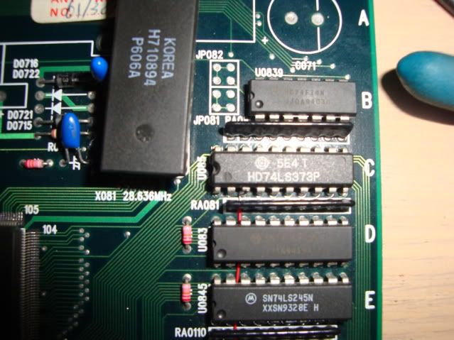
Short version - open circuit track between 74LS373 at 10C and pin 37 on the four 44 pin mask roms in the middle of the board - address lines are tied together on all 4 chips and then go to the LS373s in the top right corner. One of the address lines was no longer connected.
Not so short version - these repairlogs go in their own section on AA which is why it restates the problem at the beginning.
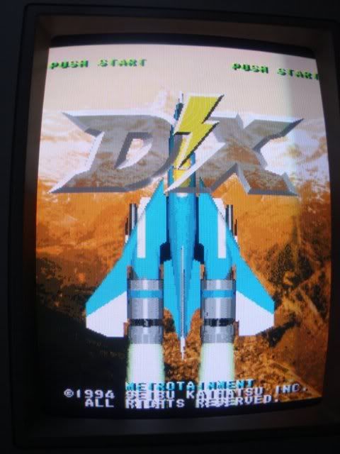
Noisuf rocked up to the Wombles lair yesturday with an unwell Raiden DX board, to be honest I had never heard of the game but it seems to be very well regarded in the shmup scene. It also seems to be a bloody expensive game board, perhaps coz its still out in wild earning money, this is probably the game thats running at my local video store - the intro seems familiar.
Anyway - the last time he played it all was well, it went back in its box, only to do this the next time he got it out for a blast.
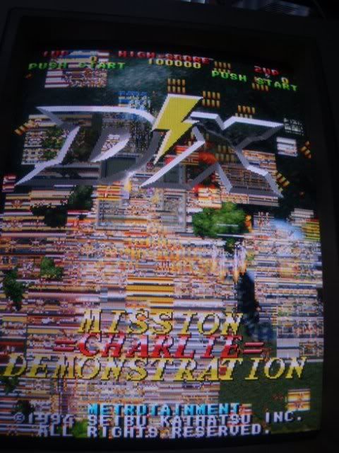
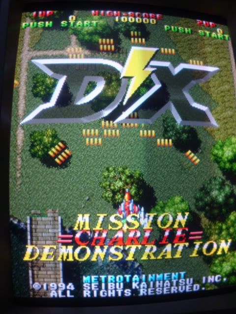
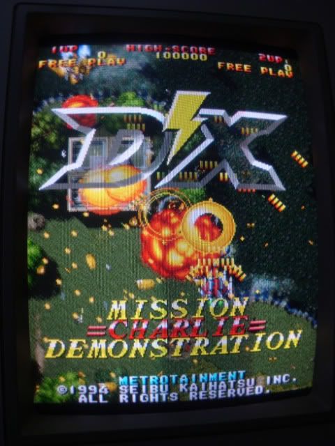
Most of the sprites were a mess even tho the backgrounds were perfect.
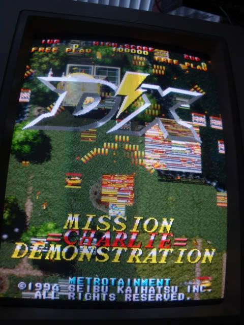
When there are a lot of objects on the screen it looks horrible.
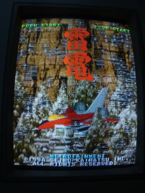
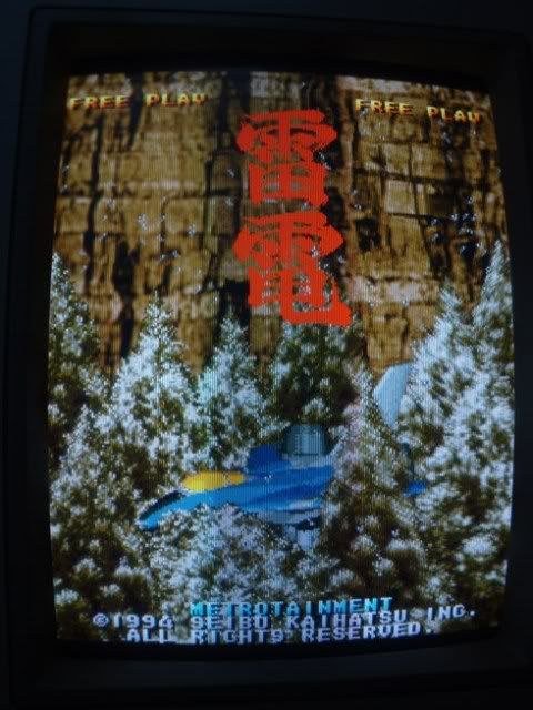
The intro where the jet fighter rises out of the cherry trees was a wreck, had no idea they were trees at this stage.
Other than that the game runs happily and is playable.
And the jet trail of the fighter is scrambled along with the sky.
This smelt like a RAM fault, not just because RAM is the most common failure on old boards, but because the game was throwing the graphics elements around the screen correctly, they were just garbled.
So we spent an afternoon going over the board, Noisuf had tracked down some good info on the shmups forum from another DX fan as to which parts of the board did what using the following photo.

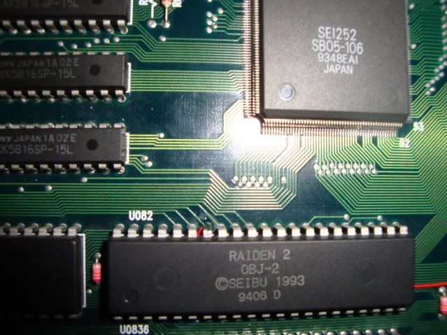
So I started off hitting the sprite RAM with a logic probe, thought I had hit gold as the lower chip in the Yellow #3 circle (which is the Sprite RAM) had stuck address lines. What was not good was that all the tracks coming out of that section went straight into the fat custom chip (Red
So moved my focus to the fat custom IC (red
So we had to move on, custom chips are a pain in the arse, you have no idea what they do, there are no datasheets, you cant even tell which pins are inputs or outputs or bidirectional. All you can do is rule out everything else except the custom, at which point the board becomes scrap if you cant find any other fault.
So went over the whole board starting at the sprite corner with the scope looking for problems, and didn't find anything, everything looked normal. Interrupting clocks around the place allowed me to prove which areas of the board were doing what, everything pointed back to the sprite corner. The LS373s were clearly involved as shorting out the clock signal replaced all sprites with blocks of coloured noise, but every pin looked healthy and busy on the scope.
Basically we burnt a lot of time checking and rechecking things, replaced one of the 74ls373 chips in the hope of proving a point, but it didn't improve anything and its activity looked identical to that of its peer. I had hoped I could get the chip off the board to test it externally but I could not clear any of legs and ended up cutting it off.
That's pretty much where we left it, I was 75% sure it was the custom that was at fault as when we hit it with freeze spray some of the sprites came good briefly, mainly because I couldn't find anything else. The odd thing was that throughout the afternoon some of the issues got better, but after the freeze spray things seemed to get worse again, back to the original level of faultiness.
This was a good example of what happens when you spend too long on a fault, you tend to get tunnel vision and end up fixated on one area. The next morning after some sleep, it occurred to me that I had only given the mask roms a cursory glance, a once over with the scope looking for bad pins or anything out of the ordinary. So I fired up the game and went round the 4 mask roms in the middle of the board. As there are some parts of the attract mode cycle which had no problems, clearly it is possible that any issue visible on the board could show up when the board is throwing sprites around.
Took me about 30 seconds to spot something nasty, pin 36 was not well on one mask rom, most of the time it was healthy looking, regular pulses, but when the crap was on the screen it had a lot of noise on it, spikes that didn't get anywhere near half way between logic 0 and 1. So went round the board with the continuity beeper to find where it connected to - other than pin 36 of the other 3 mask roms it seemed to go nowhere.
Mask roms often have strange pinouts, thankfully these didn't, and they were actually labelled with what the chips were as well as the SEIBU proprietary markings. They are TC5316200P chips, which after a bit of searching have the following pinout.
TC5316200P
A18 1 +-v-+ 42 A19
A17 2 | | 41 A8
A7 3 | | 40 A9
A6 4 | | 39 A10
A5 5 | | 38 A11
A4 6 | | 37 A12
A3 7 | | 36 A13
A2 8 | | 35 A14
A1 9 | | 34 A15
A0 10 | | 33 A16
CE/ 11 | | 32 BYTE
GND 12 | | 31 GND
OE/ 13 | | 30 D15
D0 14 | | 29 D7
D8 15 | | 28 D14
D1 16 | | 27 D6
D9 17 | | 26 D13
D2 18 | | 25 D5
D10 19 | | 24 D12
D3 20 | | 23 D4
D11 21 +---+ 22 Vdd
Pin 36 is Address line 13 (A13) so it HAS to go somewhere, finding chips with the highest address line tied low is not that uncommon but an address line in the middle has to go somewhere.
So I hit the other address lines and found that they connected back to the LS373 I had replaced and the one below. There was a gap in the A lines, and that gap was A13 on the roms and D0(pin 3) on the 373 at 10C, 16 address lines, 2 LS373s with 8 input pins each - found the bugger!
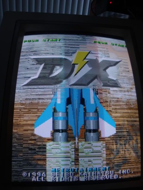
When the two pins were temporarily joined all the faults vanished, everything was perfect.
I did wonder if I had damaged the track while desoldering the chip but I hadn't. On the underside there is a short link track to a via and the pin to the via connectivity is good. On the upper side there is a track that I could eyeball all the way, and it goes to the custom IC and nowhere else, which explains why the input pin on the 373 was showing up as busy, it was busy but was only getting one of the inputs. In order to find the break I would have to take about a dozen chips off to follow it through by eye and there isn't much point. Somewhere there is a rotten track, it might be a one off, or there might be others that are not in the best health. One section of the board (nowhere near the sprite area) has black dots on the tracks under the laquer. One track clearly has just oxidised through, nothing could be done to stop it. I doubt even shaking the board about would have cause it, the areas of rot are minute and must weigh fractions of a 1000th of a mg.
So I fitted a length of hookup wire between the two pins, running under chips wherever possible to make the repair neat enough that it cant get snagged on things.
PS - the "Korea" chip was just something dark to cover up the crystal can as it keep reflecting the flash back on this shot.
Soldered to the mask rom pin, wire on the inside - fiddly but its out of the way now.
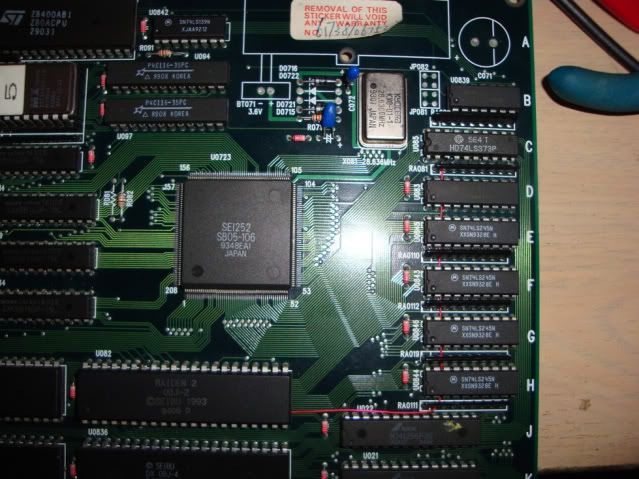
Spot the red wire running up under the LS245s and the 373!
Game has been running like a charm for the past hour and hasnt missed a beat. Think I will stick it my lowboy for a blast now.
By the way..
at this point I would like to submit my application for the award of the bodgiest electronics diagnostic tool ever. I needed to temporarily join the mask rom pin to the 373 to prove the fault, and I keep meaning (and forgetting) to make a lead with a probe at each end. So I did this.. :lol
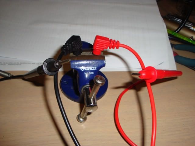
Hey it works, god knows what the resistance between the tips is tho

 | My games -


