I know you can change the Everdrive's audio output between high and low, but those should really be labeled "low" and "lower"ApolloBoy wrote:You can actually change this by going into the Everdrive's options menu.Vigormortis wrote:I suspect the Everdrive N8's expansion audio level may have been set with the AV Famicom in mind because Krikkz's demonstration videos always showed an AV Famicom.
NESRGB board available now
-
Vigormortis

- Posts: 61
- Joined: Sun Jan 19, 2014 7:07 am
Re: NESRGB board available now
-
sdekaar
- Posts: 2
- Joined: Tue Jan 21, 2014 8:17 am
Re: NESRGB board available now
nesrgb@ home
2weeks to come in France.
2weeks to come in France.
-
Voultar

- Posts: 550
- Joined: Fri Jan 10, 2014 8:29 pm
- Location: USA
Re: NESRGB board available now
For the sake of modularity, is anyone else putting their PPU's on sockets?

I believe there'll be enough clearance in the front loader, with the expansion port omitted.
I believe there'll be enough clearance in the front loader, with the expansion port omitted.
-
ApolloBoy

- Posts: 939
- Joined: Sat Jan 28, 2012 7:17 pm
Re: NESRGB board available now
I tried testing my NESRGB in my front loader and if you have both the NESRGB and PPU socketed, it won't fit. You'd either have to only socket the NESRGB or the PPU. I added a PPU socket on mine but since I'm installing it in a Twin Famicom, there's loads of room for it to fit.
-
Voultar
- Posts: 550
- Joined: Fri Jan 10, 2014 8:29 pm
- Location: USA
Re: NESRGB board available now
ApolloBoy wrote:I tried testing my NESRGB in my front loader and if you have both the NESRGB and PPU socketed, it won't fit. You'd either have to only socket the NESRGB or the PPU. I added a PPU socket on mine but since I'm installing it in a Twin Famicom, there's loads of room for it to fit.
I just dry fitted mine. It fits perfectly fine. Granted, I have no expansion port, and my sockets might be lower profile than what you used. I have low profile ZIF sockets on the mainboard for both CPU & PPU. I used the machined SIP strips on the NESRGB, though.
-
thebert
- Posts: 18
- Joined: Fri Jan 24, 2014 2:01 pm
Re: NESRGB board available now
I got my shipping confirmation on the 24th, and it arrived today! just 9 days. I live in eastern US. I was expecting it to take much longer, so I was pleasantly surprised to receive my Australian package in the mail today. 
-
CkRtech

- Posts: 668
- Joined: Mon Aug 27, 2012 9:30 pm
- Location: Seattle, WA
Re: NESRGB board available now
Congrats, thebert. We look forward to hearing about your install.
-
Vigormortis
- Posts: 61
- Joined: Sun Jan 19, 2014 7:07 am
Re: NESRGB board available now
I just installed my second NESRGB in a front loader, and I also tried swapping the SRAM out for a CY7C1399BN-12ZXC . Just like the NESRGB in my Famicom, this took care of the background palette issue. However, unlike the Famicom install, there are no weird palette switching glitches. It works perfectly. It looks like the glitches in my Famicom install are probably from the wiring and not the CY7C1399BN-12ZXC . There's no need to go out and get the 15ns version if you already ordered the CY7C1399BN-12ZXC.
I was actually kind of hoping that it would show the same glitches in the front loader. That would have meant that all I'd have to do is wait for my USB Blaster and update the NESRGB (and possibly throw the Alliance SRAM chip back in). Now that I know the CY7C1399BN-12ZXC actually works fine, I've got a lot of troubleshooting to do on that pesky Famicom.
Maybe I should give up my quest for the ultimate oldschool Famicom and just throw the NESRGB into an AV Famicom. I might have to sacrifice a bit of nostalgia for functionality.
-
alimadhi
- Posts: 30
- Joined: Sun Jan 26, 2014 12:53 pm
Re: NESRGB board available now
i asked before but no one reply 
can i install NESRGB on my Famiclone with UMC CPU & PPU UA6527P, UA6538 ?
can i install NESRGB on my Famiclone with UMC CPU & PPU UA6527P, UA6538 ?
-
mufunyo
- Posts: 176
- Joined: Thu Jun 19, 2008 11:45 am
Re: NESRGB board available now
viletim answered you a few pages back:alimadhi wrote:i asked before but no one reply
can i install NESRGB on my Famiclone with UMC CPU & PPU UA6527P, UA6538 ?
viletim wrote:I don't know. I haven't heard of anybody trying it. Let me know how it goes.alimadhi wrote:can i use NESRGB on my Family Game console has a UMC CPU & PPU UA6527P, UA6538 ?
BTW, you should set the jumpers to PAL in this case.
-
Jeppen
- Posts: 174
- Joined: Sat Dec 21, 2013 7:50 am
Re: NESRGB board available now
NESRGB installed (still with the faulty RAM) though my power regulator is getting very hot, no idea about the exact temp, but defintiely around you-really-don't-want-to-touch-it hot.
I also get some flickering on certain colors such as the pause menu in mega man 2 and also in other background colors as darker blue.
Could these be power related and is the power regulator supposed to be this darn hot?
I placed it as described in Tim's installation guide, except it's at the left screw instead of the right one of the back of the RF shield.
Where do i place the multimeter pins to check how much voltage is getting pumped into the system?
-
Voultar
- Posts: 550
- Joined: Fri Jan 10, 2014 8:29 pm
- Location: USA
Re: NESRGB board available now
On the 7805, the far left pin is input voltage, center pin is ground, and the far right pin is output voltage.
If you're wanting to know what's coming into the regulator, tap the pin on the far left. It should be 9v +/-, depending on adapter you're using.
If you're wanting to know what's coming into the regulator, tap the pin on the far left. It should be 9v +/-, depending on adapter you're using.
-
Vigormortis
- Posts: 61
- Joined: Sun Jan 19, 2014 7:07 am
Re: NESRGB board available now
A hot regulator doesn't sound right. On both my NES and Famicom, the consoles' power regulator gets warm, but nowhere near uncomfortable to the touch, and the NESRGB's regulator barely gets warm at all. Did you bridge J3? That needs to remain open if you're using the external regulator for the NESRGB.
-
Voultar
- Posts: 550
- Joined: Fri Jan 10, 2014 8:29 pm
- Location: USA
Re: NESRGB board available now
I totally agree. The NESRGB draws very little amperage. If you're powering the board with the external 7805, it should only be lukewarm, at best.Vigormortis wrote:A hot regulator doesn't sound right. On both my NES and Famicom, the consoles' power regulator gets warm, but nowhere near uncomfortable to the touch, and the NESRGB's regulator barely gets warm at all. Did you bridge J3? That needs to remain open if you're using the external regulator for the NESRGB.
-
ApolloBoy
- Posts: 939
- Joined: Sat Jan 28, 2012 7:17 pm
Re: NESRGB board available now
I checked the heat sink on Sparky's AV Fami after installing the NESRGB, and it didn't get any hotter than normal. The NESRGB only draws an extra 100 mA or so, that shouldn't be enough to generate a significant amount of heat.
-
alimadhi
- Posts: 30
- Joined: Sun Jan 26, 2014 12:53 pm
Re: NESRGB board available now
mufunyo wrote:viletim answered you a few pages back:alimadhi wrote:i asked before but no one reply
can i install NESRGB on my Famiclone with UMC CPU & PPU UA6527P, UA6538 ?viletim wrote:I don't know. I haven't heard of anybody trying it. Let me know how it goes.alimadhi wrote:can i use NESRGB on my Family Game console has a UMC CPU & PPU UA6527P, UA6538 ?
BTW, you should set the jumpers to PAL in this case.
what the jumpers ? and where ?
-
CkRtech
- Posts: 668
- Joined: Mon Aug 27, 2012 9:30 pm
- Location: Seattle, WA
Re: NESRGB board available now
Basically, follow the directions for the jumpers as mentioned for PAL in the pinout information document. http://etim.net.au/nesrgb/NESRGB-Pinout.pdf
-
alimadhi
- Posts: 30
- Joined: Sun Jan 26, 2014 12:53 pm
Re: NESRGB board available now
many thanksCkRtech wrote:Basically, follow the directions for the jumpers as mentioned for PAL in the pinout information document. http://etim.net.au/nesrgb/NESRGB-Pinout.pdf
-
Jeppen
- Posts: 174
- Joined: Sat Dec 21, 2013 7:50 am
Re: NESRGB board available now
Voultar wrote:On the 7805, the far left pin is input voltage, center pin is ground, and the far right pin is output voltage.
If you're wanting to know what's coming into the regulator, tap the pin on the far left. It should be 9v +/-, depending on adapter you're using.
I am using a matching NES-PAL-002 AC adapter (as requested under neath the NES)
Though i noticed this morning that the AC adapter was a bit warm even though the NES had been power down for at least 12 hours.
Should there really be stuff going on inside that thing without anything powered on?
This is what i get from the NESRGB
GND & Left pin = 12.18 V
GND & Right pin = 4.99 V
GND & +5 pin = 4.99 V

This is from the 7805
GND & Right pin = 4.99
GND & Left pin 12.22 V

The only thing i changed besides the NESRGB installation was that i replaced the power led for a blue one.
The only thing i changed on the NESRGB board was i shorted J4 and J7 to make it a PAL version.Vigormortis wrote:A hot regulator doesn't sound right. On both my NES and Famicom, the consoles' power regulator gets warm, but nowhere near uncomfortable to the touch, and the NESRGB's regulator barely gets warm at all. Did you bridge J3? That needs to remain open if you're using the external regulator for the NESRGB.
Any ideas?
-
Elrinth
- Posts: 307
- Joined: Thu Feb 07, 2013 2:46 pm
Re: NESRGB board available now
Awwww yeah, NESRGB arrived today... Time to get to work!
-
Jeppen
- Posts: 174
- Joined: Sat Dec 21, 2013 7:50 am
Re: NESRGB board available now
I was missing some info on this, so i thought i'd just sum it up for anyone else who might need it.
*edit Jeppen* As an alternative you could simply have have the NES powered on. (i'm pretty sure i read that in this thread)
______
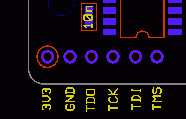
Here's a pic i found of the cable's original pin
number 1 to 10 are going from left to right in this pic.
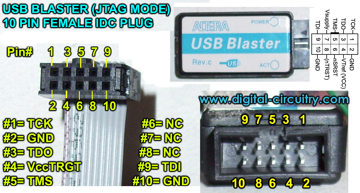
Where and what to connect to the NESRGB (Pics from Tim's site:
http://etim.net.au/nesrgb/background_fault/
JTAG Pinout
+3.3V power rail
Ground
TDO
TCK
TDI
TMS
McCracAttack's troubleshooting and success with the USB blaster:
The programmer on TIM's site is now also 13.1
My win 7 couldn't install the USB blaster drivers correctly when i plugged in the USB cable, i found this page with instructions on how to manually install the correct drivers and have your PC recognize it on Windows 7 and Vista.
Not the drivers are already on your computer in your C:/Altera folder so just follow the instructions in the below link and you'll be fine.
http://www.altera.com/download/drivers/ ... vista.html
______viletim wrote: The PLD on the NESRGB board does need power while being programmed. The programmers I have sent out have all been modified to power the board while programming it.
*edit Jeppen* As an alternative you could simply have have the NES powered on. (i'm pretty sure i read that in this thread)
______
viletim wrote: I simply installed a 3.3V LDO voltage regulator and connected the output to pin 4 (VCC sense).
You don't need to do this if you can find another way to power the board. Either by applying 3.3V to the JTAG port power terminals or +5V to the power input solder pads (near J3).

viletim wrote:The programmer comes with a short 10p IDC ribbon cable. I cut off one end and solder the wire to little piece of phenolic board with the 6p header mounted. I put tape over it afterwards which I have removed for the photo.

Here's a pic i found of the cable's original pin
number 1 to 10 are going from left to right in this pic.
Where and what to connect to the NESRGB (Pics from Tim's site:
http://etim.net.au/nesrgb/background_fault/
JTAG Pinout
+3.3V power rail
Ground
TDO
TCK
TDI
TMS
McCracAttack's troubleshooting and success with the USB blaster:
The programmer on TIM's site is now also 13.1
My win 7 couldn't install the USB blaster drivers correctly when i plugged in the USB cable, i found this page with instructions on how to manually install the correct drivers and have your PC recognize it on Windows 7 and Vista.
Not the drivers are already on your computer in your C:/Altera folder so just follow the instructions in the below link and you'll be fine.
http://www.altera.com/download/drivers/ ... vista.html
McCracAttack wrote:Oh man this was so promising! Thank you! The 13.1 programmer that came with the free Web Edition bundle can see the USB Blaster just fine! But now I'm getting a new error message.CkRtech wrote:It looks like the version that Tim supplied is Quartus II version 11.1.
The Altera website currently has a version 13.1. There is a free version and a licensed version, and the licensed version gives you a 30 day trial.
https://www.altera.com/download/sw/dnl-sw-index.jsp
Newer isn't always better, but perhaps you could give version 13.1 a try. You may need to cleanse your system of 11.1 prior to installing 13.1 - I am not certain. I haven't received a Blaster yet, so I can only make suggestions based on what I see on the web.
More fiddling. But it certainly seems like Windows 7 users need the newer software and drivers than what Tim provided.Code: Select all
Info (209060): Started Programmer operation at Thu Jan 30 22:24:25 2014
Error (209040): Can't access JTAG chain
Error (209053): Unexpected error in JTAG server -- error code 44
Error (209012): Operation failed
Info (209061): Ended Programmer operation at Thu Jan 30 22:24:25 2014
Update: Okay, I get the exact same error message when I unplug the USB Blaster from the board so it looks like my custom connector needs work.
Update 2: I've check and recheck the connections and as near as I can tell they're sound. Back to fiddling I guess.
Update 3: SUCCESS!!! According to this article some of the pins are powered by the target device. The NES had to be plugged in and turned on in order for the reprogramming to work. And work it did! The problem seems 100% fixed now! Though I guess people who were planning to reprogram boards before they installed them will have to find a way to power them first.
Thanks to nesfreak and CkRtech for your help. Hopefully someone else will learn from my mistakes.
Last edited by Jeppen on Mon Feb 03, 2014 6:33 pm, edited 2 times in total.
-
jamma
- Posts: 2
- Joined: Mon Feb 03, 2014 1:37 pm
Re: NESRGB board available now
My board turned up late last week, so a 5 hour session over the weekend and all installed and working. Very impressive kit, apart from getting the PPU out of the board it was a very easy instal.
Now waiting on the blaster to turn up to fix the fault before I tidy the cables up and get down to some real NES gaming.
Now waiting on the blaster to turn up to fix the fault before I tidy the cables up and get down to some real NES gaming.
-
game-tech.us

- Posts: 173
- Joined: Fri Aug 23, 2013 12:24 am
Re: NESRGB board available now
You shouldn't be getting 12volts at the left pins, should be more like 9, that's why they are hot, they have to converter that extra voltage to heat. Try a different ac adapter, get one with 9 Volt output and somewhere in the 1 Amp range and the right size tip of course.Jeppen wrote:Voultar wrote: I am using a matching NES-PAL-002 AC adapter (as requested under neath the NES)
Though i noticed this morning that the AC adapter was a bit warm even though the NES had been power down for at least 12 hours.
Should there really be stuff going on inside that thing without anything powered on?
This is what i get from the NESRGB
GND & Left pin = 12.18 V
GND & Right pin = 4.99 V
GND & +5 pin = 4.99 V
Any ideas?
-
Elrinth
- Posts: 307
- Joined: Thu Feb 07, 2013 2:46 pm
Re: NESRGB board available now
Ok... so... waiting for the desoldering iron to heat up, then I'm gonna desolder the PPU. Gah I was looking on the Famicom instructions over and over and missed the "Mechanical" instructions which makes it all make more sense. Having looked at ccovel's twin fami mod aswell it makes sense 
-
Jeppen
- Posts: 174
- Joined: Sat Dec 21, 2013 7:50 am
Re: NESRGB board available now
game-tech.us wrote:You shouldn't be getting 12volts at the left pins, should be more like 9, that's why they are hot, they have to converter that extra voltage to heat. Try a different ac adapter, get one with 9 Volt output and somewhere in the 1 Amp range and the right size tip of course.Jeppen wrote:Voultar wrote: I am using a matching NES-PAL-002 AC adapter (as requested under neath the NES)
Though i noticed this morning that the AC adapter was a bit warm even though the NES had been power down for at least 12 hours.
Should there really be stuff going on inside that thing without anything powered on?
This is what i get from the NESRGB
GND & Left pin = 12.18 V
GND & Right pin = 4.99 V
GND & +5 pin = 4.99 V
Any ideas?
Thanks! I will try and find one and test it.
Could that also be the cause for this "bug"?
In Mega man 2, you can see the background in the text before it appears, i tried reseting and cleaning the cartridge and pin connectors etc.. same result.


BTW i just USB Blasted the faulty RAM chip.
-
Elrinth
- Posts: 307
- Joined: Thu Feb 07, 2013 2:46 pm
Re: NESRGB board available now
gg, desoldering the ppu is quite tricky... I'll call it a night and hope for more luck tomorrow. i removed all solder on the bottom side but it's still sitting like a rock.
-
Jeppen
- Posts: 174
- Joined: Sat Dec 21, 2013 7:50 am
Re: NESRGB board available now
Elrinth wrote:gg, desoldering the ppu is quite tricky... I'll call it a night and hope for more luck tomorrow. i removed all solder on the bottom side but it's still sitting like a rock.
Best tip i can give is holding the board upright, placing your solder sucker on the bottomside ontop of the pin you wanto desolder, ready to suck, then place the soldering iron on the top side on the PPU pin, then you will clear it really well.
-
Zets13
- Posts: 142
- Joined: Wed Nov 02, 2011 10:53 pm
Re: NESRGB board available now
Yeah, it is a bit of a pain for sure. You can do a quick check by holding a board up to a light and making sure you can see light clearly through each hole. I found that using an combo iron+sucker tool can be helpful. Just go to each pin and make sure you can easily move them back and forth... If not, put a good amount of fresh solder on the pin and then suck it up.
-
CkRtech
- Posts: 668
- Joined: Mon Aug 27, 2012 9:30 pm
- Location: Seattle, WA
Re: NESRGB board available now
If only we could play "pass the Hakko 808," eh?
I used three methods when I did mine - desoldering iron with bulb attachment, soldering iron with solder sucking tube, desoldering wick.
One "half method" thing that I also did was mix in some new solder with the older solder in attempt to get it to flow a bit better.
I wicked across the pins at the top and bottom, used the desoldering w/ bulb & soldering iron with solder sucker on the bottom. I would also come back after doing a row of pins and use my tweezers to see if I could freely wiggle each pin without applying much force at all. That let me know which ones were done and which ones needed some more wick/solder suck.
Good luck!
-
eightbitminiboss
- Posts: 450
- Joined: Mon Sep 17, 2012 9:01 pm
Re: NESRGB board available now
Remember that pins 14-17 on the PPU are connected to the ground plane of the board and will require more care in desoldering. I did not heed this warning and ended up toasting my board because of it.
Anyways, here's my resulting WIP with my Twin, another one is in the mail....

Anyways, here's my resulting WIP with my Twin, another one is in the mail....