I might be interested in adding one to my top loader just like you did. I'm only going to get a board for my AV Fami once the NESRGB is back in stock, but I have my front loader prepped for it and I'd like to do the same for my top loader.leonk wrote:Is anyone looking for a Nintendo MultiAV port for their project???
NESRGB board available now
-
ApolloBoy

- Posts: 939
- Joined: Sat Jan 28, 2012 7:17 pm
Re: NESRGB board available now
-
zillion.ika
- Posts: 8
- Joined: Wed Oct 09, 2013 6:29 pm
Re: NESRGB board available now
I want to mod my PowerPak, my toploader, and my NESRGB kit to add the famicom cart audio.
If I understand correctly, the toploader does not have pin 54 in its connector which is used by the PowerPak for the extra audio, so you have to bridge pins 54 and 51 in the PowerPak.
Then do I use a 20k resistor between pins 51 and C31 on the NESRGB kit? (I was guessing that "EA(20k)" viletim mentioned was "expansion audio"?)
I don't intend to use a famicom cart adapter, just the PowerPak.
(Side note: thank you Tim, this kit is really, really well done and the quality is a dream!)
viletim wrote: Here's the NESRGB audio circuit. R92 and CA solder pad does not exist on the current version, it will be there on the next one.
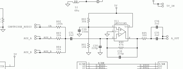
viletim wrote:I somehow managed to squeeze yet another solder pad + resistor into the layout. Now there's A(20k), B(12k), CA(100k), and EA(20k) inputs to the mixer for the next version.
-
game-tech.us

- Posts: 173
- Joined: Fri Aug 23, 2013 12:24 am
Re: NESRGB board available now
I just posted a second vid about this, final instal of the board in a top loader. Some relevant info for all.
VID LINK
VID LINK
-
RGB32E

- Posts: 1400
- Joined: Thu Nov 05, 2009 12:50 am
Re: NESRGB board available now
Fun video to watch. Did you catch a case of Drakkonitus?game-tech.us wrote:I just posted a second vid about this, final instal of the board in a top loader. Some relevant info for all.
VID LINK
Couldn't you have hot glued a segment of a hot glue stick instead of using gravity? Also, was it really a hard requirement to use the RF hole to mount the palette switch? Using the same placement for the SNES connector as the AV Famicom would have been much neater, and mount the palette switch elsewhere? Do you bend the SNES connector legs straight, or open a huge hole in the PCB?
-
leonk
- Posts: 1098
- Joined: Sun Mar 13, 2011 9:29 pm
- Location: Toronto, Canada
Re: NESRGB board available now
If you watch his other videos, you'll see he bends the pins up. The SNES multiAV allows you to bend the pins up, but requires you to cut a strange hole (with center tab) to make it fit in case. On the other hand, something like the gamecube multiAV is perfectly rectangular (easier to make a hole in the case) but the pins are not bendable because they're encased inside a metal RF shield.RGB32E wrote:Fun video to watch. Did you catch a case of Drakkonitus?game-tech.us wrote:I just posted a second vid about this, final instal of the board in a top loader. Some relevant info for all.
VID LINK
Couldn't you have hot glued a segment of a hot glue stick instead of using gravity? Also, was it really a hard requirement to use the RF hole to mount the palette switch? Using the same placement for the SNES connector as the AV Famicom would have been much neater, and mount the palette switch elsewhere? Do you bend the SNES connector legs straight, or open a huge hole in the PCB?
Jason, I agree with you.. that palette switcher doesn't look good. If the customer really wanted it, why not install it into the top shell where you used to install the AV jacks? (i.e. where the Nintendo sticker is located).
Also, all that glue doesn't look that good. Why add it at all? Are you afraid the PCB will come out of the socket?
-
mickcris

- Posts: 435
- Joined: Tue Oct 08, 2013 12:43 am
- Location: Texas, USA
Re: NESRGB board available now
That is my console in the video. I requested the switch in the rf hole as it would have just been a hole there without it. I think there is some reason why he puts the multi out where he does and cannot move it over to where it is closer middle. I would rather have it there than have to have had another hole drilled and an empty hole in the back.leonk wrote:If you watch his other videos, you'll see he bends the pins up. The SNES multiAV allows you to bend the pins up, but requires you to cut a strange hole (with center tab) to make it fit in case. On the other hand, something like the gamecube multiAV is perfectly rectangular (easier to make a hole in the case) but the pins are not bendable because they're encased inside a metal RF shield.RGB32E wrote:Fun video to watch. Did you catch a case of Drakkonitus?game-tech.us wrote:I just posted a second vid about this, final instal of the board in a top loader. Some relevant info for all.
VID LINK
Couldn't you have hot glued a segment of a hot glue stick instead of using gravity? Also, was it really a hard requirement to use the RF hole to mount the palette switch? Using the same placement for the SNES connector as the AV Famicom would have been much neater, and mount the palette switch elsewhere? Do you bend the SNES connector legs straight, or open a huge hole in the PCB?
Jason, I agree with you.. that palette switcher doesn't look good. If the customer really wanted it, why not install it into the top shell where you used to install the AV jacks? (i.e. where the Nintendo sticker is located).
Also, all that glue doesn't look that good. Why add it at all? Are you afraid the PCB will come out of the socket?
-
leonk
- Posts: 1098
- Joined: Sun Mar 13, 2011 9:29 pm
- Location: Toronto, Canada
Re: NESRGB board available now
I think it has to do with the multiAV port itself. If you look at it closely, you'll notice that it has "ears" on either side (Jason cuts one of them off to make it fit) The ear that is left is used to screw the port down. There's only so much he can move the port towards the center before the ear hits the power adapter.mickcris wrote:That is my console in the video. I requested the switch in the rf hole as it would have just been a hole there without it. I think there is some reason why he puts the multi out where he does and cannot move it over to where it is closer middle. I would rather have it there than have to have had another hole drilled and an empty hole in the back.
Jason really seems to try to do his best from a bad situation (little space and your request to install the switcher in that spot). One can always leave the hole as a hole .. or fill it (I can think of multiple ways to close that hole that will look somewhat professional)
-
cr4zymanz0r

- Posts: 358
- Joined: Sat Oct 19, 2013 6:36 am
Re: NESRGB board available now
To connect it up this way you'll need 67k total resistance between the powerpak (pin 51) and and the NESRGB audio circuit before C31 (or after R83/R84, depending on where you want to solder it). Now if Tim adds the EA(20k) solder pad that has a 20k resistor then you'd just connect pin 51 to the the EA(20k) pad with a 47k resistor.zillion.ika wrote:I want to mod my PowerPak, my toploader, and my NESRGB kit to add the famicom cart audio.
If I understand correctly, the toploader does not have pin 54 in its connector which is used by the PowerPak for the extra audio, so you have to bridge pins 54 and 51 in the PowerPak.
Then do I use a 20k resistor between pins 51 and C31 on the NESRGB kit? (I was guessing that "EA(20k)" viletim mentioned was "expansion audio"?)
I don't intend to use a famicom cart adapter, just the PowerPak.
(Side note: thank you Tim, this kit is really, really well done and the quality is a dream!)
While this will work and should give you the correct volume level, it might cause some buzzing in the audio when using a cart that isn't the powerpak. This method mixes in the sound before the circuit amps the audio, thus any possible noise will get amplified too. When the powerpak isn't being used the connection will be open and the additional wire can act somewhat as an antenna to pick up more noise. I had some issues with this on a NES frontloader for Famicom cart audio, but I don't know if your results might differ on a toploader. A shielded wire helped minimize it for me, but not eliminate it. You might not be as picky as me so you should definitely give it a try yourself and see if you're personally satisfied with the results.
The best option seems to be to mix the powerpak audio with the final audio output of the NESRGB audio circuit. I did this with the Famicom cart audio (http://shmups.system11.org/viewtopic.ph ... 26#p966726) , but with the lower audio level of the powerpak I'm not really sure what resistors would be needed for the correct volume levels or if it could be done without lowering the overall volume.
Last edited by cr4zymanz0r on Wed Nov 27, 2013 12:34 am, edited 1 time in total.
-
mickcris
- Posts: 435
- Joined: Tue Oct 08, 2013 12:43 am
- Location: Texas, USA
Re: NESRGB board available now
I dont think it looks that bad. You can always put it somewhere else, but i just figured why not use the hole that was there already if it would work. I just requested he put it there if it fit, and he said it did so we went with it.leonk wrote:I think it has to do with the multiAV port itself. If you look at it closely, you'll notice that it has "ears" on either side (Jason cuts one of them off to make it fit) The ear that is left is used to screw the port down. There's only so much he can move the port towards the center before the ear hits the power adapter.mickcris wrote:That is my console in the video. I requested the switch in the rf hole as it would have just been a hole there without it. I think there is some reason why he puts the multi out where he does and cannot move it over to where it is closer middle. I would rather have it there than have to have had another hole drilled and an empty hole in the back.
Jason really seems to try to do his best from a bad situation (little space and your request to install the switcher in that spot). One can always leave the hole as a hole .. or fill it (I can think of multiple ways to close that hole that will look somewhat professional)
-
game-tech.us
- Posts: 173
- Joined: Fri Aug 23, 2013 12:24 am
Re: NESRGB board available now
Yes i'm worried about the rgb board coming out of the socket, but as I said in the vid, only because I have to ship it! Who knows how hard it will get knocked around during transit...
I can't believe that little bit of hot glue looks bad to you Leon! LOL
Great idea about using a slice of the stick rgb32e!
I would definitely prefer a non hot glue solution, but that would mean either no sockets between the rgb and mobo or a stand off mount hole added to the rgb board.
I think the snes multi hole was put where it was put because it wouldn't totally take up the rf hole if I moved it over toward the center, not tall enough to hit the top of that hole and be solidly sitting on the mobo. This may not be the case with a GC multi, if it's a perfect rectangle, it may be taller and could maybe fill both the rf and 3-4 holes? However I do not like the idea of cutting a hole in the mobo to access the pins, nor installing it upside down to be able to access them from the top.
I like the new palette switch better than the supplied one, and it went in the rf hole with ease, I just don't like how far the threads stick out, but in order to reach the actuator it has to be that far out...
I've also ordered a bunch of 9 pin mini dins that appear to be compatible with sega genesis 2 cords and are panel mount! Ebay link. I might do as Tim did and have a break out board made for this as well to ease installation, but it will be a few weeks before I even get the damn things as they are coming from china... Unless somebody in the US has a couple of these to spare that I can play with!?!?
-
game-tech.us
- Posts: 173
- Joined: Fri Aug 23, 2013 12:24 am
Re: NESRGB board available now
I also just tried it and with the round pin headers I bought off ebay, china seller again, I can mount Tim's board without sockets. My headers are not the same as the ones in Tim's kit though, they are a bit taller, and caps do still need worked down against the mobo. I may do all my customers NES's this way to avoid heavy hot glue and socket use to ensure it will not come out unintentionally.
-
alamone
- Posts: 754
- Joined: Wed Mar 09, 2011 10:32 pm
Re: NESRGB board available now
I just want to confirm that the adapter PCB just wires all of the lines straight thru, with the exception of EXT0-EXT3 being tied to GND?
I had to desolder the lot a few times and want to make sure I didn't mess up any traces.
I had to desolder the lot a few times and want to make sure I didn't mess up any traces.
-
Shining

- Posts: 197
- Joined: Mon Jan 16, 2012 6:14 pm
- Location: Sweden
Re: NESRGB board available now
So, is there any reason to stay with the Playchoice PPU and not do this mod? Any compatibility issues or graphical glitches?
-
ApolloBoy
- Posts: 939
- Joined: Sat Jan 28, 2012 7:17 pm
Re: NESRGB board available now
So far, it looks like the NESRGB has rendered the RGB PPU mod totally obsolete.Shining wrote:So, is there any reason to stay with the Playchoice PPU and not do this mod?
-
Moosmann
- Posts: 26
- Joined: Fri Jan 18, 2008 10:23 pm
- Location: Germany
- Contact:
Re: NESRGB board available now
I compare the PSone Rockman 3/Mega Man 3 Complete Works to the NES Version with the 3 palettes from Tims RGB Board this weekend. I will take the palette that look like the PSone Version. I think, these will be the right colors.
The RGB Board works great, picture is sharp and good. But: One game look like composite video:
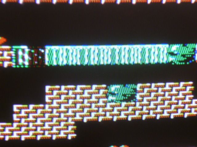
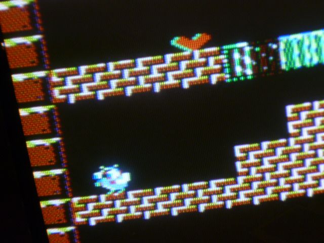
I use the Powerpak and all other 3 games looks in RGB, but Duck Maze is a exceptional case.
Greetings Markus
The RGB Board works great, picture is sharp and good. But: One game look like composite video:
I use the Powerpak and all other 3 games looks in RGB, but Duck Maze is a exceptional case.
Greetings Markus
-
leonk
- Posts: 1098
- Joined: Sun Mar 13, 2011 9:29 pm
- Location: Toronto, Canada
Re: NESRGB board available now
Strange you noticed that.
One thing to keep in mind is that RGB is still an analog signal, and as such, it can be effected by the slightest amount of noise. That is why shielding, proper grounding, proper cable is so important. I think Jason was also able to prove that in his YouTube video, by using a cheap AC adapter vs original NES one.
I personally like this solution more than the PC10 PPU because it's a lot more flexible (and cheaper!). Not only do you have full control of the color palette, but you are also able to easily chose your video out source (composite, svideo or RGB). In addition, the PC10 mod to some extend still has jail bars. The NESRGB has no jail bars.. I can't even see them on my LCD TV that is able to bring out jail bars on the original front loader!!
-
RGB

- Posts: 527
- Joined: Sat Aug 04, 2007 3:11 pm
- Location: Europe
Re: NESRGB board available now
If it's not too late, I have an idea for an upgrade for the next version. It would be cool to cycle through the palletes using one button instead of the switch. Or even better - you could make use of the reset button on the NES for this and if you held it for 3 seconds, the pallete would be switched.
-
Shining
- Posts: 197
- Joined: Mon Jan 16, 2012 6:14 pm
- Location: Sweden
Re: NESRGB board available now
Thanks. Is it possible to install the NESRGB board directly into an already Playchoice PPU modded AV Famicom?ApolloBoy wrote:So far, it looks like the NESRGB has rendered the RGB PPU mod totally obsolete.Shining wrote:So, is there any reason to stay with the Playchoice PPU and not do this mod?
-
Konsolkongen

- Posts: 2399
- Joined: Fri May 16, 2008 8:28 pm
- Location: Denmark
Re: NESRGB board available now
Should be pretty easy with some basic PIC programming skills. Can't be much different than the "Ultimate Saturn mod". I have no experience with this yet, so just a guessRGB wrote:If it's not too late, I have an idea for an upgrade for the next version. It would be cool to cycle through the palletes using one button instead of the switch. Or even better - you could make use of the reset button on the NES for this and if you held it for 3 seconds, the pallete would be switched.
-
RGB
- Posts: 527
- Joined: Sat Aug 04, 2007 3:11 pm
- Location: Europe
Re: NESRGB board available now
It is easy, but would be awesome to have it already on the NESRGB PCB  If it's not possible at this point, I might do it using some small AVR, like the attiny (that is, when I get to order the NESRGB).
-
leonk
- Posts: 1098
- Joined: Sun Mar 13, 2011 9:29 pm
- Location: Toronto, Canada
Re: NESRGB board available now
You will need to rip out the PPU and amp, leaving only the empty PPU socket + external connectors (can't reuse these parts). In addition, you will need to source a famicom/NES PPU as the original one is needed, but was tossed out when you did the mod.Shining wrote:Thanks. Is it possible to install the NESRGB board directly into an already Playchoice PPU modded AV Famicom?ApolloBoy wrote:So far, it looks like the NESRGB has rendered the RGB PPU mod totally obsolete.Shining wrote:So, is there any reason to stay with the Playchoice PPU and not do this mod?
It might make more sense to sell this system on eBay, and start fresh with an NESRGB.
-
lettuce

- Posts: 1336
- Joined: Wed Jun 22, 2011 7:10 pm
- Location: Bedfordshire, England.
Re: NESRGB board available now
How would one mod a front loader NES with the RGBNES pcb for the famicom extra audio channel, if just going to be using a EverDrive NES flash cart (so no famicom adapter involved)?
-
mvsfan
- Posts: 1209
- Joined: Sat Oct 06, 2012 12:24 am
Re: NESRGB board available now
2.) Solder a wire to NES expansion pin 40 (like this, but without the resistor http://i.imgur.com/nNixYV3.jpg). On the other end of the wire connect a 1.2k resistor. The next step will show you where to connect it.
I want to do this but Your diagram shows expansion pin 46 as the expansion audio pin.
Which one is it 40 or 46?
i got my nesrgb installed successfully and i like the way it sounds and looks.
I noticed that even composite video is nice out of this nesrgb.
rgb is amazing. much better than my playchoice Nes.
there is really no reason to do the playchoice mod anymore it is obsolete. looks like everything that was wrong about the playchoice mod has been fixed with nesrgb. Felix the cat works, Bram stokers dracula doesnt turn blue when you pass a certain point etc etc.
Thanks tim for this great product.
-
ApolloBoy
- Posts: 939
- Joined: Sat Jan 28, 2012 7:17 pm
Re: NESRGB board available now
Pin 46 is for the Famicom.mvsfan wrote: I want to do this but Your diagram shows expansion pin 46 as the expansion audio pin.
Which one is it 40 or 46?
-
Moosmann
- Posts: 26
- Joined: Fri Jan 18, 2008 10:23 pm
- Location: Germany
- Contact:
Re: NESRGB board available now
I connect my RGB NES via Composite Video (NES Video Out). Picture is white and grey. I play Duck Maze, the picture is in color, but some objects only in white (e.g. the red heart). A other unlicensed russian game "Morskoy Boy" look black & white with RGB, but via NES Composite Video Out in color.
The NESRGB Board can maybe only support games which are developed in RGB, but not some unlicensed russian/asian games which are not progammed natively in rgb.
My "old" NES with Playchoice PPU don`t have the 74 "HC" 373 Mod to Run the Powerpack, so that I cannot test them how these games works. Anyone can test these two games/roms on a PC10 PPU Moddes NES ?
Greetings Markus
-
antron

- Posts: 2861
- Joined: Wed Feb 22, 2006 7:53 pm
- Location: Egret 29, USA
Re: NESRGB board available now
Mooseman, are you sure your tv is not switching to composite when you play duck maze?
-
Skips
- Posts: 404
- Joined: Tue Oct 22, 2013 3:03 am
Re: NESRGB board available now
No I loaded up duck maze with my everdrive using both a BVM-20F1U and a CVS287 RGB to component encoder. Duckmaze looks like hammered shit on both. Its something with the game, romfile, everdrive, or maybe the NESRGB kit. Its not his setup.antron wrote:Mooseman, are you sure your tv is not switching to composite when you play duck maze?
I am no longer taking free or paid modding projects, please do not contact me asking for my services. Thanks .
-
parodius

- Posts: 732
- Joined: Wed Jan 26, 2005 5:54 am
- Location: Singapore
Re: NESRGB board available now
Same here with Duck Maze. The title screen is proper RGB though.
My sales thread : 2020/07/20..MASTER.VER.
-
viletim
- Posts: 565
- Joined: Mon Aug 07, 2006 6:44 am
- Location: Sydney, Australia
- Contact:
Re: NESRGB board available now
There are multiple ground wires for a typical installation (audio connector, video connector, palette switch, power regulator). It would be difficult to connect all these wires to a single point.leonk wrote:1) The installation instructions could be better. :) Some gotcha's that I ran into:
- there are multiple GND points marked on PCB, but what are they for? Just to be safe, I connected them all to ground.
- can the pinout PDF on the site be rotated 90 degrees for better viewing during install?
- there are no instructions on how to install the top loader adapter - I guessed (NESRGB is socketed into adapter - adapter is soldered into NES)
- as already mentioned, the solder side of the top loader adapter sits on top of the CPU and pins can touch. I trimmed them and used electrical tape on CPU just in case
- CPU pin 1 & 2 could be identified in docs - I knew what they were, some might not
The diagrams are generated with my CAD software. I can't rotate them but you should be able to do it with your viewer. The idea behind the adapter is that it's soldered to the NESRGB board so they both become one solid piece.
I'll do that. The round pins are a special part which I don't buy locally. I had only just enough for the NESRGB boards and I had to make do with what I could get to supply with the adapters.game-tech.us wrote: I do however think square headers should not be supplied, just two pairs of round headers to keep confusion down and also the round ones won't need trimmed off.
The parts supplied don't cost very much. If I offer different options it makes order fullfillment too complicated. Maybe you can use the parts on another project.leonk wrote:Tim, have you considered selling kits that only have PCB + headers? I got a bag of parts that I didn't use that probably cost 10-15$.
It's too late. Anyway, I have no MCU on board so it's not such a simple request. A three second delay is quite costly in PLD logic blocks if I had to divide the pixel clock down to get it.RGB wrote: If it's not too late, I have an idea for an upgrade for the next version. It would be cool to cycle through the palletes using one button instead of the switch. Or even better - you could make use of the reset button on the NES for this and if you held it for 3 seconds, the pallete would be switched.
I don't know why these two games don't work correctly. The NES composite video shouldn't be anything other than grey/white when a palette is selected. If you see colour it means the game has found a way to write data into the PPU's palette registers without the NESRGB board intercepting it.Moosmann wrote:I connect my RGB NES via Composite Video (NES Video Out). Picture is white and grey. I play Duck Maze, the picture is in color, but some objects only in white (e.g. the red heart). A other unlicensed russian game "Morskoy Boy" look black & white with RGB, but via NES Composite Video Out in color.
No, nothing like that. If anything, these two unlicensed games might be doing something strange with the PPU becasue the programmer didn't have access to the architecture documentation. I had a look at the trapped PPU register writes in a debugging emulator for both Morskoy Boy and Duck Maze but I didn't seen anything unusual.Moosmann wrote:The NESRGB Board can maybe only support games which are developed in RGB, but not some unlicensed russian/asian games which are not progammed natively in rgb.
-
mufunyo
- Posts: 176
- Joined: Thu Jun 19, 2008 11:45 am
Re: NESRGB board available now
To be honest, from Moosmann's photos, it looks like the palette is being changed alternately between scanlines, causing some sort of dithering effect. If it's off-by-one, it would start flickering similar to composite video crosstalk. The photos don't really look like composite at all (the picture is way too sharp), and I can't really see a logical explanation for it. The blanking voltage on the SCART plug does exactly that, it blanks the composite signal, so if a game interferes with NESRGB operation in any way you should just get a black screen; it can't fall back to composite (unless the blanking voltage drops too).