cr4zymanz0r wrote:viletim wrote:
The PowerPak flash cartridge generates audio too??
I just read about it a bit more an it seems the audio level from the PowerPak is lower than a standard Famicom cartridge. That's unfortunate. I'm not going to add a point on the mixer circuit specially for the PowerPak.
Here's the NESRGB audio circuit. R92 and CA solder pad does not exist on the current version, it will be there on the next one.
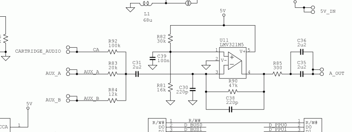
The R92 resistor value is incorrect. When using Famicom carts with expansion audio in a front loader NES virtually every mod I've seen involves putting a 100k ohm resistor in the Famicom adapter. The 100k resistor is connecting to pin 46 (audio out) of the Famicom cart slot of the connector. There's technically different pins on the NES side of the connector it can be routed to but most people seem to use pin 18 with a 4.7uF capacitor there too (not sure if the capacitor is really necessary or just a safety precaution). Now pin 18 on the NES cart slot goes to NES expansion port pin 40. (On a stock NES front loader sound circuit) They then must solder a wire to connect NES expansion pin 40 to NES expansion pin 3 (audio in). Now after expansion pin 3 there's a 20K resistor that connects to the NES sound circuit, so that's a total of 120k ohm resistance before the Famicom audio enters the NES sound circuit. So technically you would make the R92 resistor in your schematic 120k ohm, but I wouldn't recommend that.
Just because everybody does it doesn't mean it's right. The original Famicom's audio circuit equivalent of R90 is 100k instead of 47k in the NES (and NESRGB). After A and B APU signals are mixed together the audio enters the cartridge through the audio input pin is mixed inside the cartridge and returns through the audio output pin. This most cartridges just connect the in and out pins together so it is safe to assume that games which do add extra audio do not amplify the signal any further.
When connecting Famicom audio to the NES your aim is to feed the audio into the point where A and B signal are mixed. If you wanted to feed the audio into the same position in the Famicom's audio signal you would use a 100k series resistor as this would result in a gain of 1 (R90/R92 = 100/100). In the case of the NES and NESRGB R90 is 47k this makes the gain 0.47 (R90nes/R90fam = 47/100) times the the Famicom level (1). So the desired gain desired for the Famicom cartridge audio is 0.47 (R90/R92 = 47/100) in order to have it match the level of the A and B signals as they would be on the Famicom.
Once you account for the value of the 20k already in there you end up with the ideal value of 80k for the NES. Of course this is all academic. The actual difference is probably not enough to notice without comparing them side by side.
cr4zymanz0r wrote:
Here's why:
1.) putting the total 120K ohm resistance on the NESRGB sound circuit would technically work but everyone wanting to do this (on a NES system) is already going to have to do at least some small mod to their Famicom cart adapter. Most have already modded it with the 100K resistor to use in a regular front loader NES since the other 20K is built into the sound circuit.
2.) The powerpak does emulate the Famicom sound in supported games and the audio coming from the powerpak is quieter than the audio coming from a Famicom cart, thus needing less resistance. If you integrate the entire 120K resistance into the NESRGB sound circuit for cartridge audio input then the powerpak audio would be too quiet
I would recommend you make the R92 resistor 20K ohm. This would make it just like the audio in (NES expansion pin 3) on the NES front loader. Then everyone with already modded Famicom cart adapters with a 100K resistor in them will work on the NESRGB sound circuit without change (once the system is wired), and powerpak users can put their needed 47k resistor between NES expansion pin 9 and 40 (or straight to the NESRGB cartridge audio input if they don't care about wiring up Famicom cart audio.
Thanks for the explanation of the usual solution. There's one significant problem with this approach. It's noisy.
The high impedance audio input sharing and edge connector with two digital buses is bad enough but to then amplify the that noise further and inject it into the audio signal. When you place a 100k resistor in your Famicom adapter there is now a high impedance path between this point and the CA point on the NESRGB board. Any noise signal at this point will be amplified by 2.4 (R90/R92 = 47/20).
The best approach is to place R90 it its entirety a close to the mixing point as possible. This way you get a low impedance path (audio from the output pin) all the way to the mixing circuit. If noise is picked up it is only amplified by 0.47 anyway. Perhaps the audio input pin could be bypassed with some capacitance so the cartridges with no expansion audio can have a low impedance path too.
The only reason I put an audio circuit on the NESRGB board is because the one in the NES/Famicom isn't so great. If I make the same mistakes as the original circuit it defeats the purpose.


