I use two sockets on the rgb amp/ cleaned sync or component encoding pcbs with the pc10 chip so yeah it will just fit. Plus the headers I use are a bit too long.ApolloBoy wrote:What about with the front loader? There's not that much vertical clearance in the front loader and I don't think a socketed NESRGB with a socketed PPU and RF shield would fit.acidhammer420k wrote:No, you can definitely make it fit, and leave the RF cover on too. Yes even with a socket.
NESRGB board available now
-
game-tech.us

- Posts: 173
- Joined: Fri Aug 23, 2013 12:24 am
Re: NESRGB board available now
-
acidhammer420k
- Posts: 85
- Joined: Mon Mar 18, 2013 7:56 pm
- Location: 01840
Re: NESRGB board available now
Like I said I've never taken apart a toploader myself or know what the insides look like, but the shell the same apart from the coax/AV out should be the same, but if you're installing a NESRGB I'd think you'd be ditching the RF box, haha
-
leonk
- Posts: 1098
- Joined: Sun Mar 13, 2011 9:29 pm
- Location: Toronto, Canada
Re: NESRGB board available now
With top loader you almost have to! You need the space for new rgb out connector!
-
ApolloBoy

- Posts: 939
- Joined: Sat Jan 28, 2012 7:17 pm
Re: NESRGB board available now
There's enough space to install one and a 3.5 mm audio jack without resorting to removing the RF modulator, but if you don't want to drill additional holes it's the best way to do it. You could also drill out the channel select switch hole and you'd have an ideal place for the audio jack.leonk wrote:With top loader you almost have to! You need the space for new rgb out connector!
-
zillion.ika
- Posts: 8
- Joined: Wed Oct 09, 2013 6:29 pm
Re: NESRGB board available now
Just a word of warning for anyone using the Famicom/top loader adapter:
The pins that come with the adapter PCB are not the same size as the ones that come with the RGB kit and will not fit in the headers!
The pins that come with the adapter PCB are not the same size as the ones that come with the RGB kit and will not fit in the headers!
-
ccovell

- Posts: 203
- Joined: Mon Feb 14, 2005 3:03 am
- Location: Japan
- Contact:
Re: NESRGB board available now
My NESRGB came in and I saw if I could make it work in my Twin Famicom.
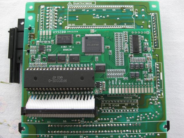
As Drakon showed, the Twin Fami has space on the underside for the RGB board, but since the PPU has to be flipped upside-down, one of the two rows of pins has to be rerouted through an adaptor. (viletim could help us out by printing such a PCB to do the job.)
I ordered an AVFamicom PPU adaptor from tim's page, and the headers that shipped with it came in handy: even though they are oversize for socket holes, etc, they are the perfect size for an IDE header to simply slide onto. A 40-pin IDE cable makes a good 20-wire adaptor cable for the Twin Fami's PPU.
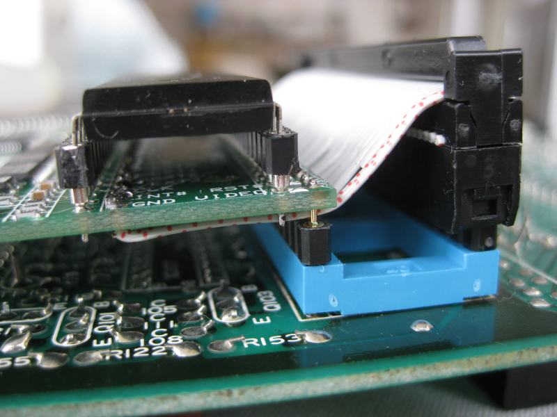
Since there is *roughly* 2.5cm of space under the PCB inside the Twin, there is room to use sockets for (almost) everything, as doing this kind of mod is a harrowing experience for me, and I didn't want anything to be permanently soldered.

The layering on the left is:
1) PPU
2) Sockets provided with the NESRGB
3) NESRGB
4) IDE cable soldered in for pins 1-20 and fed between the legs of pins 21-40
5) Double-sided header that came with the NESRGB
6) Blue 40-pin socket to Famicom PCB
The layering on the right is:
1) IDE cable & connector
2) Long double-sided header that came with the AV Fami adaptor board
3) Blue 40-pin socket to Famicom PCB
The 40-pin socket has simple tabs for accepting the AV Fami's header, since machined sockets don't accept the oversized header.
Tentatively, everything works for now! I tested Comp + S-Video with several FDS games, and they look and play beautifully. So, thanks viletim for the board and Drakon for the idea!
As Drakon showed, the Twin Fami has space on the underside for the RGB board, but since the PPU has to be flipped upside-down, one of the two rows of pins has to be rerouted through an adaptor. (viletim could help us out by printing such a PCB to do the job.)
I ordered an AVFamicom PPU adaptor from tim's page, and the headers that shipped with it came in handy: even though they are oversize for socket holes, etc, they are the perfect size for an IDE header to simply slide onto. A 40-pin IDE cable makes a good 20-wire adaptor cable for the Twin Fami's PPU.
Since there is *roughly* 2.5cm of space under the PCB inside the Twin, there is room to use sockets for (almost) everything, as doing this kind of mod is a harrowing experience for me, and I didn't want anything to be permanently soldered.
The layering on the left is:
1) PPU
2) Sockets provided with the NESRGB
3) NESRGB
4) IDE cable soldered in for pins 1-20 and fed between the legs of pins 21-40
5) Double-sided header that came with the NESRGB
6) Blue 40-pin socket to Famicom PCB
The layering on the right is:
1) IDE cable & connector
2) Long double-sided header that came with the AV Fami adaptor board
3) Blue 40-pin socket to Famicom PCB
The 40-pin socket has simple tabs for accepting the AV Fami's header, since machined sockets don't accept the oversized header.
Tentatively, everything works for now! I tested Comp + S-Video with several FDS games, and they look and play beautifully. So, thanks viletim for the board and Drakon for the idea!
http://www.chrismcovell.com
Chris' Journey
Chris' Journey
-
Pasky

- Posts: 699
- Joined: Mon Oct 21, 2013 3:58 am
Re: NESRGB board available now
Needs more hot glue.
-
markfrizb
- Posts: 83
- Joined: Fri Mar 25, 2011 2:32 pm
Re: NESRGB board available now
That made me laugh! Good one !
-
rolins

- Posts: 575
- Joined: Tue Feb 21, 2006 7:28 pm
- Location: Nevada
Re: NESRGB board available now
I got mine yesterday in the mail and installed it in my frontloader. Very impressed with the results. The only downside on my part is my monitor. I have an Amiga 1080 monitor and it wouldn't take either comp sync or TTL sync from the NESRGB board. Had to build a LM1881 sync stripper to get it working.
-
Colonel Skills
- Posts: 1
- Joined: Mon Nov 11, 2013 4:04 pm
Re: NESRGB board available now
A little late to the party here, but I'd like to snag one of these myself. Is there a system in place for alerting when you're taking orders again or should I just check on a routine basis?
-
KKEYSER4063
- Posts: 23
- Joined: Sat Jan 07, 2012 10:30 pm
- Location: Arizona, United States
Re: NESRGB board available now
Subscribing to this thread would keep you in-the-know.Colonel Skills wrote:A little late to the party here, but I'd like to snag one of these myself. Is there a system in place for alerting when you're taking orders again or should I just check on a routine basis?
-
evil_ash_xero

- Posts: 6268
- Joined: Thu Jul 12, 2007 6:33 am
- Location: Where the fish lives
Re: NESRGB board available now
zillion.ika wrote:Just a word of warning for anyone using the Famicom/top loader adapter:
The pins that come with the adapter PCB are not the same size as the ones that come with the RGB kit and will not fit in the headers!
So, does this mean that the adapter that comes with the board does not work with a top loader? Can someone confirm this?
My Collection: http://www.rfgeneration.com/cgi-bin/col ... Collection
-
rCadeGaming
- Posts: 242
- Joined: Mon Dec 05, 2011 12:04 am
Re: NESRGB board available now
Viletim, I just noticed something on the board pinout pdf:
http://etim.net.au/nesrgb/NESRGB-Pinout.pdf
There are three jumpers for PPU type, encoded video type, and luma trap frequency for encoded video. For the first two of those, the jump is left open for NTSC, or connected for PAL, whereas the last is the opposite. I just noticed the inconsistency there, and wanted to make sure that is by design, not just a typo in the PDF.
Can you confirm?
My Analog A/V setup: http://shmups.system11.org/viewtopic.php?f=6&t=43992
Ultimate Shmup Stick! JLF mod: http://shmups.system11.org/viewtopic.php?f=6&t=41451
Ultimate Shmup Stick! JLF mod: http://shmups.system11.org/viewtopic.php?f=6&t=41451
-
zillion.ika
- Posts: 8
- Joined: Wed Oct 09, 2013 6:29 pm
Re: NESRGB board available now
evil_ash_xero wrote:zillion.ika wrote:Just a word of warning for anyone using the Famicom/top loader adapter:
The pins that come with the adapter PCB are not the same size as the ones that come with the RGB kit and will not fit in the headers!
So, does this mean that the adapter that comes with the board does not work with a top loader? Can someone confirm this?
It works with the top loader, you just need to be sure to use the header pins that come with the NES RGB kit on the bottom of the adapter board (where the adapter board will be connecting to the socket).
The pins that are packaged with the adapter board are square and need to connect to the top of the adapter board. Hope that made sense.
-
undamned

- Posts: 3273
- Joined: Sat Jan 29, 2005 9:27 am
- Location: Phoenix


-
antron

- Posts: 2861
- Joined: Wed Feb 22, 2006 7:53 pm
- Location: Egret 29, USA
Re: NESRGB board available now
Hell yeah! Amiga-NES
-
viletim
- Posts: 565
- Joined: Mon Aug 07, 2006 6:44 am
- Location: Sydney, Australia
- Contact:
Re: NESRGB board available now
The Famicom installation guide is done.
http://etim.net.au/nesrgb/installation-famicom/
http://etim.net.au/nesrgb/installation-famicom/
It is regular composite when the palette switch is set to off. When a palette is selected it will be off colour (no colour in fact).sammargh wrote:viletim if you leave the composite video output hooked up as-is and don't run it through the outputs on the NESRGB pcb will it still be regular composite output or will the picture be off-color because of the ppu stuff going on?
It will not fit inside the front loader if the PPU is socketed. As others say, apparently it will fit in the A/V Famicom and Famicom Twin and NES top loader with the socket in place.ApolloBoy wrote:Tim says it won't fit that way in the front loader and I don't think it would with the top loader or AV Fami either.leonk wrote:I can see that the PPU solders to the NESRGB. Does it makes sense to socket it? Will it have clearance in the system (toaster or top loader) if it's installed like this?
I'll look into it.ccovell wrote:As Drakon showed, the Twin Fami has space on the underside for the RGB board, but since the PPU has to be flipped upside-down, one of the two rows of pins has to be rerouted through an adaptor. (viletim could help us out by printing such a PCB to do the job.)
The document is correct. It's inconsistent but that's just the way it is.rCadeGaming wrote:Viletim, I just noticed something on the board pinout pdf:
http://etim.net.au/nesrgb/NESRGB-Pinout.pdf
There are three jumpers for PPU type, encoded video type, and luma trap frequency for encoded video. For the first two of those, the jump is left open for NTSC, or connected for PAL, whereas the last is the opposite. I just noticed the inconsistency there, and wanted to make sure that is by design, not just a typo in the PDF.
-
Hamburglar
- Posts: 213
- Joined: Thu Jul 07, 2011 9:55 am
Re: NESRGB board available now
What's the recommended way to do the "stereo" mod for the toaster NES if also using the NESRGB?
-
antron
- Posts: 2861
- Joined: Wed Feb 22, 2006 7:53 pm
- Location: Egret 29, USA
Re: NESRGB board available now
I guess it still provides sync, right? What do you think of the theory that the PPU video might provide the best sync possible?viletim wrote:It is regular composite when the palette switch is set to off. When a palette is selected it will be off colour (no colour in fact).sammargh wrote:viletim if you leave the composite video output hooked up as-is and don't run it through the outputs on the NESRGB pcb will it still be regular composite output or will the picture be off-color because of the ppu stuff going on?
-
robneal81
- Posts: 43
- Joined: Sun Oct 07, 2012 1:45 am
Re: NESRGB board available now
Right...and how should we route Famicom expansion audio to work through the stereo mod, when using the NESRGB?Hamburglar wrote:What's the recommended way to do the "stereo" mod for the toaster NES if also using the NESRGB?
Game-tech modded my current NES and did the stereo mod. It's really awesome and I couldn't go back to playing in mono. I have a knob that goes from all the way mono, to all the way stereo. I mostly keep it in the middle, but some games (like Contra) are really amazing in full-stereo.
-
game-tech.us
- Posts: 173
- Joined: Fri Aug 23, 2013 12:24 am
Re: NESRGB board available now
I've had to connect the exp audio to one channel or the other and use a much lower value resistor, like 300 Ohms, to get it up to the levels of the stereo channels, at least in the stereo mod version I use...robneal81 wrote:Right...and how should we route Famicom expansion audio to work through the stereo mod, when using the NESRGB?Hamburglar wrote:What's the recommended way to do the "stereo" mod for the toaster NES if also using the NESRGB?
Game-tech modded my current NES and did the stereo mod. It's really awesome and I couldn't go back to playing in mono. I have a knob that goes from all the way mono, to all the way stereo. I mostly keep it in the middle, but some games (like Contra) are really amazing in full-stereo.
-
sammargh
- Posts: 24
- Joined: Sat Oct 26, 2013 3:28 pm
Re: NESRGB board available now
It's more to know if I need to cut the composite video trace on the AV Famicom to have color composite video output rather than sync. Yes, I plan on using RGB but I also would like the capability of composite/s-video as well since it is a multi-av port.antron wrote:I guess it still provides sync, right? What do you think of the theory that the PPU video might provide the best sync possible?viletim wrote:It is regular composite when the palette switch is set to off. When a palette is selected it will be off colour (no colour in fact).sammargh wrote:viletim if you leave the composite video output hooked up as-is and don't run it through the outputs on the NESRGB pcb will it still be regular composite output or will the picture be off-color because of the ppu stuff going on?
-
ApolloBoy
- Posts: 939
- Joined: Sat Jan 28, 2012 7:17 pm
Re: NESRGB board available now
You'll need to as the standard composite video will only work properly if you leave the palette switch "off".sammargh wrote:It's more to know if I need to cut the composite video trace on the AV Famicom to have color composite video output rather than sync. Yes, I plan on using RGB but I also would like the capability of composite/s-video as well since it is a multi-av port.
-
loopyeddie

- Posts: 63
- Joined: Mon Oct 10, 2005 4:09 pm
Re: NESRGB board available now
If following sammargh's guide for using the AV Famicom multi-video output, can I use this cable as long as I remove the caps from inside the cable?
eBay SCART cable
eBay SCART cable
-
rCadeGaming
- Posts: 242
- Joined: Mon Dec 05, 2011 12:04 am
Re: NESRGB board available now
Thanks. Just wanted to make sure before installing.viletim wrote:The document is correct. It's inconsistent but that's just the way it is.
My Analog A/V setup: http://shmups.system11.org/viewtopic.php?f=6&t=43992
Ultimate Shmup Stick! JLF mod: http://shmups.system11.org/viewtopic.php?f=6&t=41451
Ultimate Shmup Stick! JLF mod: http://shmups.system11.org/viewtopic.php?f=6&t=41451
-
ApolloBoy
- Posts: 939
- Joined: Sat Jan 28, 2012 7:17 pm
Re: NESRGB board available now
You can, or you can remove the caps on the NESRGB for the RGB lines so that you can use that cable with your SNES (if you have one that is).loopyeddie wrote:If following sammargh's guide for using the AV Famicom multi-video output, can I use this cable as long as I remove the caps from inside the cable?
eBay SCART cable
-
cr4zymanz0r

- Posts: 358
- Joined: Sat Oct 19, 2013 6:36 am
Re: NESRGB board available now
I would also like to know this, but personally I'm fine with mono on NES. I'm not a huge audio buff, but the front loader NES does have a low buzz/hum on the audio that's especially noticeable at higher volumes on quiet and silent screens such as title screens. If it wasn't for that I would be fine with the stock NES audio circuit, but I hear the audio circuit on the nesrgb board fixes the buzzing. The problem is I haven't seen anyone mention how to mix Famicom expansion audio from games such as Akumajo Densetsu and Gimmick! into the nesrgb board's audio circuit.robneal81 wrote: Right...and how should we route Famicom expansion audio to work through the stereo mod, when using the NESRGB?
The mod required for the stock NES frontloader audio circuit is two parts:
1.) Mod the Famicom to NES cart adapter to connect Famicom cart pin 46 to NES cart pin 18 with a 100K ohm resistor and a 4.7uF capacitor (positive leg facing the NES pin 18). NES pin 18 is routed to pin 40 on the unused NES expansion connector.
2.) Pin 40 on the NES expansion connector must be connected to pin 3 (audio-in) on the expansion connector. This allows the NES to mix the Famicom extra audio into the NES sound output.
Now I don't know 100% what's going on with the mixing but I think (correct me if I'm wrong) this mod essentially mixes the Famicom expansion audio into the end of the NES audio circuit and the 100K ohm resistor mentioned above is to bring to the volume level of the Famicom expansion audio down to the right level so it's not too loud compared to the audio coming from the system.
Now for the nesrgb's audio circuit. It taps audio directly from the CPU pins thus does not account for Famicom expansion audio. Would adding that be as simple as basically doing the usual mod listed above but connecting NES expansion pin 40 to the final audio output of the nesrgb board? Depending on the volume level of the nesrgb's audio circuit I understand the resistor mentioned above might need to be higher or lower than 100k ohm (it'd be great if someone already knows what value). Would something this simple work to mix in the Famicom expansion audio or am I over-simplifying things? The least work with the proper sounding result is what I'm hoping for
-
loopyeddie
- Posts: 63
- Joined: Mon Oct 10, 2005 4:09 pm
Re: NESRGB board available now
Awesome, thank you. I do have a SNES but it will probably be hooked up at the same time, so I will need an additional cable.ApolloBoy wrote:You can, or you can remove the caps on the NESRGB for the RGB lines so that you can use that cable with your SNES (if you have one that is).
-
sammargh
- Posts: 24
- Joined: Sat Oct 26, 2013 3:28 pm
Re: NESRGB board available now
Hooray! Thanks viletim, it works great!
Since everyone loves solder-porn

Here's the top notice the removed 220uF caps as I'm using a OEM RGB cable through the multi-av out port

And here's the bottom. Be aware that I cleaned up those straggler wires that was just an in-the-process pic
There's 1 capacitor on the motherboard you have to desolder & bend over a bit to make room labeled C5. I also apologize for my lack of superglue use. Soldering the system up in this fashion has made it so I did not have to make any modifications to the case except cut the trace for composite video. That can easily be jumped over should I wish to remove the mod and go fully-stock.
Since everyone loves solder-porn
Here's the top notice the removed 220uF caps as I'm using a OEM RGB cable through the multi-av out port
And here's the bottom. Be aware that I cleaned up those straggler wires that was just an in-the-process pic
There's 1 capacitor on the motherboard you have to desolder & bend over a bit to make room labeled C5. I also apologize for my lack of superglue use. Soldering the system up in this fashion has made it so I did not have to make any modifications to the case except cut the trace for composite video. That can easily be jumped over should I wish to remove the mod and go fully-stock.