So I finally finish the soldering, connect the supergun to the TV (it's a German one so I have it connected via Scart), connect an old Tetris PCB I got for testing, switch the supergun on, then get some kind of reaction (similar to when you switch on a console, just a couple of white stripes on the screen for a short moment), then the screen goes to black and nothing happens.
I have done the following things:
- checked if the wires have all been correctly connected and properly soldered (all fine)
- checked the voltages supplied by the power adapter again, they're fine
- checked if there are any electrical shortages, couldn't find any
I can't guarantee that the Tetris PCB works; I do have an NG mobo that I know works but I'm kinda afraid of using it for testing...
any suggestions?
edit: I used this guy's tutorial (all in German, I'm afraid):
http://www.systemshock.info/supergun-bauanleitung.htm
(mod edit - moved to hardware forum)
Help needed - homebuilt supergun doesn't work
-
ChurchOfSolipsism

- Posts: 1476
- Joined: Thu Sep 25, 2008 12:12 am
-
Jockel

- Posts: 3073
- Joined: Tue May 20, 2008 5:15 pm
- Location: Berlin, Germany
- Contact:
Re: Help needed - homebuilt supergun doesn't work
Try another PCB.
-
ChurchOfSolipsism
- Posts: 1476
- Joined: Thu Sep 25, 2008 12:12 am
Re: Help needed - homebuilt supergun doesn't work
Right. Took the plunge, connected a NG mobo which I know works with exactly the same results.
Any other ideas?
Any other ideas?
-
RGB

- Posts: 526
- Joined: Sat Aug 04, 2007 3:11 pm
- Location: Europe
Re: Help needed - homebuilt supergun doesn't work
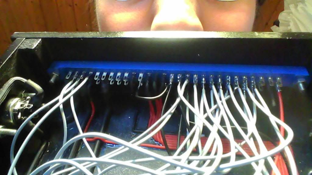
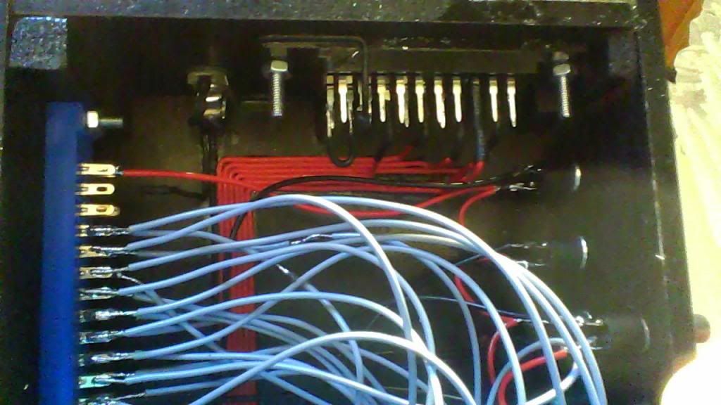
Could you post a good quality picture of the internals of your supergun ?
-
ChurchOfSolipsism
- Posts: 1476
- Joined: Thu Sep 25, 2008 12:12 am
Re: Help needed - homebuilt supergun doesn't work
Problem is, I don't have a camera (not even a smartphone). Let me try to use this very big laptop's built in camera...
right, does this help in any way?
http://i110.photobucket.com/albums/n105 ... guninsides.
http://i110.photobucket.com/albums/n105 ... 192819.jpg
http://i110.photobucket.com/albums/n105 ... 192838.jpg
http://i110.photobucket.com/albums/n105 ... 192828.jpg
right, does this help in any way?
http://i110.photobucket.com/albums/n105 ... guninsides.
http://i110.photobucket.com/albums/n105 ... 192819.jpg
http://i110.photobucket.com/albums/n105 ... 192838.jpg
http://i110.photobucket.com/albums/n105 ... 192828.jpg
-
ChurchOfSolipsism
- Posts: 1476
- Joined: Thu Sep 25, 2008 12:12 am
Re: Help needed - homebuilt supergun doesn't work
Just measured the voltages on the board (where the PCB connects to the Jamma harness), the Tetris PCB is getting 4.8 and 12.2 volts. Maybe the 4.8 is not enough...?
-
system11

- Posts: 6325
- Joined: Tue Jan 25, 2005 10:17 pm
- Location: UK
- Contact:
Re: Help needed - homebuilt supergun doesn't work
It should be, and for 2 PCBs to do the exact same thing is unusual - it's more likely that your TV doesn't like what it's seeing, do you have all the SCART grounds connected, format pin etc?
System11's random blog, with things - and stuff!
http://blog.system11.org
http://blog.system11.org
-
gray117
- Posts: 1235
- Joined: Fri Jul 25, 2008 10:19 pm
- Location: Leeds
Re: Help needed - homebuilt supergun doesn't work
Given that you're getting some sort of signal I'd guess at this: Is the tv definitely in rgb mode? Many tvs require the rgb blanking on scart and/or need to be switched to rgb mode. Some tvs only need this to switch, others may require this blanking signal continuously to then stay in rgb mode [whether or not there's a button on the remote for it).
I take it the tv works fine from other other, say, console rgb 240p sources?
I take it the tv works fine from other other, say, console rgb 240p sources?
-
ChurchOfSolipsism
- Posts: 1476
- Joined: Thu Sep 25, 2008 12:12 am
Re: Help needed - homebuilt supergun doesn't work
Unfortunately, there's no way for me to verify if the TV accepts RGB signals since I don't have any RGB consoles. Don't have a manual for my TV, couldn't find a pdf of it on the net nor any other information on it.
Anyway, checked the SCART-pins again, pin 16 ("Blanking signal up/ RGB-selection voltage up" according to Wikipedia) is connected to the Jamma harness.
Anyway, checked the SCART-pins again, pin 16 ("Blanking signal up/ RGB-selection voltage up" according to Wikipedia) is connected to the Jamma harness.
-
ChurchOfSolipsism
- Posts: 1476
- Joined: Thu Sep 25, 2008 12:12 am
Re: Help needed - homebuilt supergun doesn't work
Interesting new development: apparently, when I switch on the supergun, I get to the PCB's test menu (haven't found a way to leave it yet; pressing the service or test buttons or any combination of P1/2 start and Coin 1/2 does nothing, and the PCB doesn't have any dip switches). Thing is, picture is almost black, I can barely make out the dark grey letters, which is why during the day I couldn't see anything, so I had to assume it didn't work.
Is this an interesting new clue or does it mean that I have fucked up and can start over again?
Is this an interesting new clue or does it mean that I have fucked up and can start over again?
-
system11
- Posts: 6325
- Joined: Tue Jan 25, 2005 10:17 pm
- Location: UK
- Contact:
Re: Help needed - homebuilt supergun doesn't work
Video ground missing? Common for 'too dark' situations.
System11's random blog, with things - and stuff!
http://blog.system11.org
http://blog.system11.org
-
shmuppyLove

- Posts: 3708
- Joined: Thu Apr 07, 2011 1:44 pm
- Location: Toronto
Re: Help needed - homebuilt supergun doesn't work
If every time a board boots it goes into the service menu, check the connections to JAMMA pin 'R' on the solder side - this is where your service switch should go.
Make sure the button you're using is not the normally closed type (aka NC or "push-to-break"). You want a normally open "push-to-make" SPST momentary contact button for this. Or maybe you've accidentally grounded this pin?
Make sure the button you're using is not the normally closed type (aka NC or "push-to-break"). You want a normally open "push-to-make" SPST momentary contact button for this. Or maybe you've accidentally grounded this pin?

-
Crafty+Mech

- Posts: 395
- Joined: Sat Jan 19, 2013 1:17 am
Re: Help needed - homebuilt supergun doesn't work
If you are stuck in service mode, also check the dip switch settings to make sure test mode has not been selected. If you have the Atari Tetris board, the service menu is triggered by dip switch, not the service button.
Last edited by Crafty+Mech on Wed May 01, 2013 11:12 pm, edited 1 time in total.
-
system11
- Posts: 6325
- Joined: Tue Jan 25, 2005 10:17 pm
- Location: UK
- Contact:
Re: Help needed - homebuilt supergun doesn't work
Actually you want a toggle switch for test mode - Namco games particularly are fond of exiting test as soon as the button is released.
System11's random blog, with things - and stuff!
http://blog.system11.org
http://blog.system11.org
-
caius

- Posts: 136
- Joined: Mon Mar 25, 2013 10:07 pm
- Location: Italy
Re: Help needed - homebuilt supergun doesn't work
Hi, did you tie +5v from PSU to Pin 16 of SCART via a 100ohm resistor?
Go to this page and check if your wiring is the same:
http://www.gameland.gr/geoanas/realarcade.htm#scart
Also the author of the page had similar problem:
Go to this page and check if your wiring is the same:
http://www.gameland.gr/geoanas/realarcade.htm#scart
Also the author of the page had similar problem:
Code: Select all
The only problems I had were when I didn't connect the blanking pin (the picture synced up but everything was n-
RGB
- Posts: 526
- Joined: Sat Aug 04, 2007 3:11 pm
- Location: Europe
Re: Help needed - homebuilt supergun doesn't work
I modified the original wiring diagram - connect 5V to #16 via a 100ohm resistor as suggested by caius and also connect 5V to pin #8. Additionally, you can connect GND directly from the PSU, instead of the video GND from the jamma edge.
http://oi44.tinypic.com/2qjd744.jpg
edit: pin #18 should also be connected to video GND.
http://oi44.tinypic.com/2qjd744.jpg
edit: pin #18 should also be connected to video GND.
-
caius
- Posts: 136
- Joined: Mon Mar 25, 2013 10:07 pm
- Location: Italy
Re: Help needed - homebuilt supergun doesn't work
OK, but I think that pin 8 of SCART must be tied to +12V in order to auto-switch to AV channel.RGB wrote:I modified the original wiring diagram - connect 5V to #16 via a 100ohm resistor as suggested by caius and also connect 5V to pin #8. Additionally, you can connect GND directly from the PSU, instead of the video GND from the jamma edge.
http://oi44.tinypic.com/2qjd744.jpg
edit: pin #18 should also be connected to video GND.
-
ChurchOfSolipsism
- Posts: 1476
- Joined: Thu Sep 25, 2008 12:12 am
Re: Help needed - homebuilt supergun doesn't work
Thanks so much fellas!
Btw the SCART cable turned out to be fucked as well (finally got the bright idea to check the pins of the cable late last night), so I ordered a new one, which should arrive tomorrow. I'll try everything you suggested and report back.
Btw the SCART cable turned out to be fucked as well (finally got the bright idea to check the pins of the cable late last night), so I ordered a new one, which should arrive tomorrow. I'll try everything you suggested and report back.
-
RGB
- Posts: 526
- Joined: Sat Aug 04, 2007 3:11 pm
- Location: Europe
Re: Help needed - homebuilt supergun doesn't work
Pin #8 is used to bring the TV out of standby mode and set it to AV mode (or just switch to AV if the TV's already turned on). When you apply +5V to this pin, the TV's going to display in 16:9 and if +12V, in 4:3. However, from my experience, most of TVs just switch to AV 4:3 if you give the +5V and only a few are able to display in a letterbox (16:9). It's safe to say, that both options, +5V and +12V are ok : )caius wrote:OK, but I think that pin 8 of SCART must be tied to +12V in order to auto-switch to AV channel.RGB wrote:I modified the original wiring diagram - connect 5V to #16 via a 100ohm resistor as suggested by caius and also connect 5V to pin #8. Additionally, you can connect GND directly from the PSU, instead of the video GND from the jamma edge.
http://oi44.tinypic.com/2qjd744.jpg
edit: pin #18 should also be connected to video GND.
-
ChurchOfSolipsism
- Posts: 1476
- Joined: Thu Sep 25, 2008 12:12 am
Re: Help needed - homebuilt supergun doesn't work
Again, thanks a bunch for the advice. One more thing though: Some helpful dude on arcadeotaku posted this wiring diagram:RGB wrote: Pin #8 is used to bring the TV out of standby mode and set it to AV mode (or just switch to AV if the TV's already turned on). When you apply +5V to this pin, the TV's going to display in 16:9 and if +12V, in 4:3. However, from my experience, most of TVs just switch to AV 4:3 if you give the +5V and only a few are able to display in a letterbox (16:9). It's safe to say, that both options, +5V and +12V are ok : )
He insists that I need to solder in all those resistors as otherwise the signal will be too strong and I might end up destroying my TV. Since you haven't really said anything about this until now, I thought I'd ask again and dispense with the additional resistors if they're not strictly necessary in your opinion...
-
RGB
- Posts: 526
- Joined: Sat Aug 04, 2007 3:11 pm
- Location: Europe
Re: Help needed - homebuilt supergun doesn't work
I don't think that the lack of resistors on the R, G, B lines will destroy your TV, but you'll need them to attenuate the colour signals, otherwise the picture will be too bright. Ideally, you want to install potentiometers so that you can adjust the brightness. Resistor on the sync line is a pretty good idea, too, it stabilizes the picture for some PCBs - but again, a potentiometer would allow you to adjust it.
-
ChurchOfSolipsism
- Posts: 1476
- Joined: Thu Sep 25, 2008 12:12 am
Re: Help needed - homebuilt supergun doesn't work
Status report: I get a perfect picture with the new Scart cable. Still ordered 1K potentiometers and will put them in.
The 'PCB stuck in test menu' problem could be solved as well, something silly I had tried had gone wrong. Desoldered a wire and now the game boots properly.
On to audio - funnily, when I turn up the volume on the Tetris PCB, I start getting image interference (even if I turn the knob a tiny bit), which gets even worse when I press the P1 coin button, i.e. the whole image gets distorted for a short moment. Also, I don't seem to get any sound except noise interference, even when the volume know on the PCB is turned all the way down (I soldered the headphone jack to L and 10 on the jamma harness)
edit: maybe this info is useful: the wires for sound + and - are also connected to the relevant pins on the Scart cable. Since it was a cheap one, is it possible the missing insulation of the individual wires causes interference?
-
RGB
- Posts: 526
- Joined: Sat Aug 04, 2007 3:11 pm
- Location: Europe
Re: Help needed - homebuilt supergun doesn't work
Here's your answer (unfortunately):ChurchOfSolipsism wrote:On to audio - funnily, when I turn up the volume on the Tetris PCB, I start getting image interference (even if I turn the knob a tiny bit), which gets even worse when I press the P1 coin button, i.e. the whole image gets distorted for a short moment. Also, I don't seem to get any sound except noise interference, even when the volume know on the PCB is turned all the way down (I soldered the headphone jack to L and 10 on the jamma harness)
There is no relevant pin for the speaker "-" on the Scart cable. PCBs output amplified mono audio and this "-" is yours speakers negative, not channel left. You should only connect "+" (JAMMA pin #10) and turn the volume down on your PCB, or use an attenuation circuit to reduce the amplified power level, as shown in the diagram from AO.ChurchOfSolipsism wrote:edit: maybe this info is useful: the wires for sound + and - are also connected to the relevant pins on the Scart cable. (...)
I don't want to scare you, but there's a real chance that you've just damaged your TV. You see, the image interference was directly connected with the audio, like you said - when you turned up the volume on the pcb or pressed the coin button (high pitched sound?), you would see noise etc.
If the image interference persists with the corrected audio wiring then you will know it's something with the TV..
-
kowal

- Posts: 122
- Joined: Wed Jul 19, 2006 3:32 pm
- Contact:
Re: Help needed - homebuilt supergun doesn't work
Hi
You use female scart socket on case right?
sync must come to pin 19 not 20. because oryginal scart coross audio and sync
gnd must come to 17 and 18
If you use high quality real coaxial scart gnd only need to come to 17 because sync gnd is also corossed (17->18)
if TV stuck on composite video you get this image

incorret GND on pin 17 or 18 you get image with noise on cheap scart cable change connector side

You use female scart socket on case right?
sync must come to pin 19 not 20. because oryginal scart coross audio and sync
gnd must come to 17 and 18
If you use high quality real coaxial scart gnd only need to come to 17 because sync gnd is also corossed (17->18)
if TV stuck on composite video you get this image
incorret GND on pin 17 or 18 you get image with noise on cheap scart cable change connector side
-
ChurchOfSolipsism
- Posts: 1476
- Joined: Thu Sep 25, 2008 12:12 am
Re: Help needed - homebuilt supergun doesn't work
Corrected the wiring and the image was still "noisy" when I tried the Tetris PCB (also, I got only very little sound and lots of noise out of the PCB). Assuming I'd killed my favourite CRT TV, I felt like a tool for a minute, then decided to try out my PGM motherboard - which runs perfectly, including fantastically clear sound and picture?! Ha, the TV remains undamaged, but now the Tetris PCB is somehow fucked (?), which I can perfectly live with since I bought it for trying everything out.RGB wrote: There is no relevant pin for the speaker "-" on the Scart cable. PCBs output amplified mono audio and this "-" is yours speakers negative, not channel left. You should only connect "+" (JAMMA pin #10) and turn the volume down on your PCB, or use an attenuation circuit to reduce the amplified power level, as shown in the diagram from AO.
I don't want to scare you, but there's a real chance that you've just damaged your TV. You see, the image interference was directly connected with the audio, like you said - when you turned up the volume on the pcb or pressed the coin button (high pitched sound?), you would see noise etc.
If the image interference persists with the corrected audio wiring then you will know it's something with the TV..
RIGHT, on to the controls (which consist of stick & buttons in a tupperware box
http://i110.photobucket.com/albums/n105 ... 161711.jpg
-
ChurchOfSolipsism
- Posts: 1476
- Joined: Thu Sep 25, 2008 12:12 am
Re: Help needed - homebuilt supergun doesn't work
Wired up my ghetto stick and it works like a charm. Been playing PGM and Neo Geo games the whole afternoon, all thanks to the great people of this forum. Life's sweet sometimes. 