Heys guy, I need your help. I'm in the planning stages of making my own supergun and I'm stuck on the controller. I need to know how I can configure a genesis controller for a supergun (yes I know it's only 3 buttons). I know I have to remove the chip and then by pass wires, but I don't know where on the pcb to solder those wires. I've searched extensively for a detailed guide on how to do this but haven't found anything. I PMed a guy about it on here but he hasn't responded to me.
Also, I need to know what wires on the genesis controller each color stands for, you know like ground or up and down. When you open the standard genesis 1 controller the wires in the cord are different colors.
Thanks in advance
Sega Genesis controller help
-
the black_7

- Posts: 41
- Joined: Sat Jan 17, 2009 3:32 pm
- Location: Hampton, Virginia
-
brokenhalo

- Posts: 1409
- Joined: Wed Mar 26, 2008 4:11 am
- Location: philly suburbs
how many wires are in the genesis cord? i'm looking at this picture here
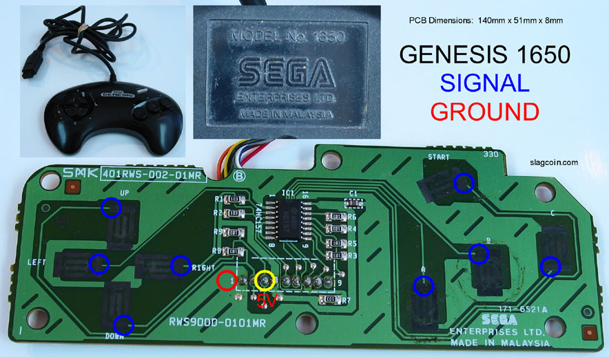
you can see the row of soldering connections in the center of the controller pcb. there's nine of them, so that would correspond to: up, down, left, right, A, B, C, start, common ground (not necessarily that order). you can easily trace the paths to see which spot corresponds to what. the diagram has a 5 volt spot marked, but looking at the trace, it looks like that spot actually corresponds to down. you might be good to go as is (not sure about removing the chip though. someone else will have to chime in about that. i don't have any supergun experience.)
edit. it looks like if you remove that chip it might break a couple paths. the wires you mentioned are probably just needed to jumper those paths. if you desolder the chip and post some pics i can probably show you what you would need to jumper. should be simple.
-
the black_7
- Posts: 41
- Joined: Sat Jan 17, 2009 3:32 pm
- Location: Hampton, Virginia
Thanks man. I PMed a couple of people about the chip but this is definitely a step in the right direction for me. Maybe somebody else can help me with the rest.
EDIT: Maybe I should be more specific with my plans. I don't intend to use the original cord with my supergun, but a 15 pin Dsub one. I am under the impression that I have to remove the chip initially. After that I plan on adding two buttons. Once I have every thing wired the way I want, I planned on attaching the colored wires you can see there on the picture, plus the added wires from the buttons I'm going to add and connecting it all to a 15 pin cord (I know that's a lot of work but I really want to use these controllers and am adverse to the 6 button genesis controller).
EDIT: Maybe I should be more specific with my plans. I don't intend to use the original cord with my supergun, but a 15 pin Dsub one. I am under the impression that I have to remove the chip initially. After that I plan on adding two buttons. Once I have every thing wired the way I want, I planned on attaching the colored wires you can see there on the picture, plus the added wires from the buttons I'm going to add and connecting it all to a 15 pin cord (I know that's a lot of work but I really want to use these controllers and am adverse to the 6 button genesis controller).
-
the black_7
- Posts: 41
- Joined: Sat Jan 17, 2009 3:32 pm
- Location: Hampton, Virginia
-
dpful

- Posts: 1205
- Joined: Tue Feb 01, 2005 5:19 pm
- Location: SLC, UT, US
- Contact:
If I was going to use another chord, (plus add buttons), I wouldn't worry about collors or anything. I would just remove the chip- or cut the traces to the chip (just to be sure it doesn't interfere), and then solder the wires directly to the nubs each button leads to- even scrape and solder directly to a trace if need be.
One wire for each button and one wire for common ground (which you could get to each button easily if it wasn't already traced). Then apply that to the added buttons also.
er, I guess just take the chip out of the equation and then be very mechanical about it, whether following wires or traces-- each button connecting 1 wire to the common ground. Any inconsistencies or breaks in the traces or the wires, just patch or cut traces for shorts.
-
the black_7
- Posts: 41
- Joined: Sat Jan 17, 2009 3:32 pm
- Location: Hampton, Virginia
...Dude. You don't know how much of a life saver you are. There have been like hundred or so views to this thread, and no one except like two people have had anything to add 
.... Let me see if I got this straight. You're saying remove the chip. There are eight little nubs attached to either side of the chip, does it matter which row I start soldering to or will I find which side when I start testing to find out what each nub is for? Once I remove the chip and solder wires to the appropriate nubs, where do the other ends of the wires go? Once soldered to the nubs, do I simply gather the other ends of the wires and connect them to a hacked cord like a neo extension cable or a vga cord, you know the 15 pin ones?
.... Let me see if I got this straight. You're saying remove the chip. There are eight little nubs attached to either side of the chip, does it matter which row I start soldering to or will I find which side when I start testing to find out what each nub is for? Once I remove the chip and solder wires to the appropriate nubs, where do the other ends of the wires go? Once soldered to the nubs, do I simply gather the other ends of the wires and connect them to a hacked cord like a neo extension cable or a vga cord, you know the 15 pin ones?
-
the black_7
- Posts: 41
- Joined: Sat Jan 17, 2009 3:32 pm
- Location: Hampton, Virginia
Okay so from all the information you guys gave me, I think I've gathered there are two ways I can do this. Tell me if I'm on the right track or if I've gone totally off into never never land again. (I'm thinking I might use vga cords or neo extension cords for it instead of the original cords by the way).
1. I remove the chip. Find out what each nub that's left on either side of where the chip was. Cut the genesis cord. hack any cord I desire and solder the wires from that cord to those nubs that were left over. (Question about that solution. There are eight solder nubs on either side of that chip. Am I right in guessing that on each side four of those are for signals ( up, down, a, b, etc.) and four are grounds?)
2. I remove the chip. Take small wires and solder them from one nub directly across to the solder core. ( I'm not sure where that is exactly).... I'm a little lost on the second one. Help me out iatneho.
Where am I at so far? BTW I know I will only need one ground
-
iatneH

- Posts: 3202
- Joined: Tue Jan 25, 2005 11:09 pm
- Location: Vancouver, BC, Canada
I have found some pictures of my Saturn pad and Genesis 6-button pad.
I don't have any pictures of 3-button Genesis pads since I gave mine away and don't work with them anymore, but the principle should be the same.
Saturn pad:

The column on the left is where each core of the cable is attached to the PCB; The row on the bottom are the leftover nubs, traced to each button's live end.
This is an older picture which still used the original cable; I replaced this with a different cable later, just desolder the original cable and solder in the new cores. Note that the original GND line must be cut away - see next picture
Genesis 6-button pad:

Same idea as above. The top row is the nubs, each corresponding to one button's live end. The bottom are the core entry points. Notice the grey wire at the very left. This used to be GND, but to change it to a data line, I used a knife to cut the surrounding copper trace. GND was then changed to be the black wire.
Hope this helps you more.
-
the black_7
- Posts: 41
- Joined: Sat Jan 17, 2009 3:32 pm
- Location: Hampton, Virginia
So that row of solder blobs, with the 5v yellow circle on it on the genesis 3-button controller picture up there, is the "cable core" ? Is that right?
After I remove the chip I solder one end to the right nubs, where the chip was, then I solder the other end to the appropriate solder blob on the "cable core". Is that right?
Instead of desoldering the old cable core for a new cord, after I do all the soldering on the top of the pcb, cant' I just cut the colored wires from the original cord and just connect them to a hacked cord of my own?
-
iatneH
- Posts: 3202
- Joined: Tue Jan 25, 2005 11:09 pm
- Location: Vancouver, BC, Canada
Not sure what you mean by 5v yellow circle, but the bottom row is where my own cable is soldered in, and the top row connects to the buttons.the black_7 wrote:So that row of solder blobs, with the 5v yellow circle on it on the genesis 3-button controller picture up there, is the "cable core" ? Is that right?
ExactlyAfter I remove the chip I solder one end to the right nubs, where the chip was, then I solder the other end to the appropriate solder blob on the "cable core". Is that right?
You can do this, but in my experience, the individual wires in the original cord do not take well to repeated twisting/flexing and may break at the point where they join your hacked cable/connector. But maybe I just did a sloppy job.Instead of desoldering the old cable core for a new cord, after I do all the soldering on the top of the pcb, cant' I just cut the colored wires from the original cord and just connect them to a hacked cord of my own?
-
dpful
- Posts: 1205
- Joined: Tue Feb 01, 2005 5:19 pm
- Location: SLC, UT, US
- Contact:
Yeah, you can attach the wires any way. I think that the main thing is that, on "up" for example, theres two traces leading to right where the botton presses- one is ground, and one is "up's" signal wire (the ground one is the one that connects to all the other buttons, the signal one is the one that doesn't). When you press the button, it connects those, and your dude goes "up".
So, same for every button- one ground wire (that splits) and goes to one side of every button, and 9 signal wires (that stay isolated, and go each to the other side of every corresponding button). With that attitude, you can (one at a time) follow the traces, bridge any inconsistancies, remove any chips in the way, and end up with a clear, uninterupted path from the ground to each button pad, and an isolated path for each buttons signal wire. On more convoluted control pads, I've even cut the traces, scraped and soldered right to the traces just outside the button pads just to make it more simple. But that genesis pad should be pretty easy to navigate if you just go one button at a time.
Of course, you need the pinout from the supergun to match so all the wires are going to the right place in the end.
It boils down to- "up" signal wire needs to touch "common ground", by way of button press- can't touch anything else- no chips on the line- no physical short circuits- whatever it takes. then repeat for every button.
-
the black_7
- Posts: 41
- Joined: Sat Jan 17, 2009 3:32 pm
- Location: Hampton, Virginia