yeah so obtaining a sanwa autofire circuit is impossible it seems, are there any other manufacturers or is there another way of obtaining autofire?
maybe it is possible to slaughter an old console controller somehow?
does anyone have any tips for a stable circuit? (i already have a shitty one)
Arcade Autofire?
-
sven666

- Posts: 4545
- Joined: Wed Feb 02, 2005 2:04 am
- Location: sweden
- Contact:
Arcade Autofire?
the destruction of everything, is the beginning of something new. your whole world is on fire, and soon, you'll be too..
-
EOJ

- Posts: 3227
- Joined: Fri Mar 11, 2005 6:12 am
- Location: Hawaii
- Contact:
-
sven666
- Posts: 4545
- Joined: Wed Feb 02, 2005 2:04 am
- Location: sweden
- Contact:
-
Dave_K.

- Posts: 4571
- Joined: Wed Jan 26, 2005 5:43 am
- Location: SF Bay Area
- Contact:
-
segasonicfan

- Posts: 456
- Joined: Tue Jul 04, 2006 5:20 am
- Contact:
I also designed a great working autofire circuit a while back (you posted on the thread so you probably remember) using a 555 timer. If you're up to building it I can give you the schematic I made. It's not quite as versatile as the sanwa ones (you need one circuit per button) but it definitely gets the job done right.
-Segasonicfan
-Segasonicfan
-
sven666
- Posts: 4545
- Joined: Wed Feb 02, 2005 2:04 am
- Location: sweden
- Contact:
yeah i remember that, the one i have now is based on the 555 (i think, i didint make it) but it works like shit =/ id rather get a professionally made one that definetly works.segasonicfan wrote:I also designed a great working autofire circuit a while back (you posted on the thread so you probably remember) using a 555 timer. If you're up to building it I can give you the schematic I made. It's not quite as versatile as the sanwa ones (you need one circuit per button) but it definitely gets the job done right.
-Segasonicfan
these days im too lazy and not poor enough to break out my dusty soldering iron
the destruction of everything, is the beginning of something new. your whole world is on fire, and soon, you'll be too..
-
rtw

- Posts: 1959
- Joined: Wed Jan 26, 2005 6:46 pm
- Location: Norway
- Contact:
sven666 you are just lazysven666 wrote:yeah i remember that, the one i have now is based on the 555 (i think, i didint make it) but it works like shit =/ id rather get a professionally made one that definetly works.
these days im too lazy and not poor enough to break out my dusty soldering ironsad but true..
enough. I proved that last time I visited you but you need to do it
right i.e. solder cables properly etc.
Ideally you would want it on some kind of Jamma connector
which you would put between your PCB and the original.
rtw
http://world-of-arcades.net
The future of ST-V rests upon our work and your work
The future of ST-V rests upon our work and your work
-
sven666
- Posts: 4545
- Joined: Wed Feb 02, 2005 2:04 am
- Location: sweden
- Contact:
no actually the one i have is extremely irradic in its autofire rate and even when it does work it usually wears off after a few minutes (like its overheating or something, lol).rtw wrote: sven666 you are just lazyThe one you have works good
enough. I proved that last time I visited you but you need to do it
right i.e. solder cables properly etc.
Ideally you would want it on some kind of Jamma connector
which you would put between your PCB and the original.
rtw
the destruction of everything, is the beginning of something new. your whole world is on fire, and soon, you'll be too..
-
PC Engine Fan X!
- Posts: 9784
- Joined: Wed Jan 26, 2005 10:32 pm
Using auto-fire hack with arcade PCBs is well worth it...
I've got a Deluxe Atari Jaguar Jamma Joystick that was custom-made for me by Dan Loosen of the famous www.goatstore.com site and further modded by Matt Ross to have auto-fire capabilities for all three buttons + DB-15 Neo-Geo pinout for use with Supergun setup...
I like the ability to turn on auto-fire for the older Jamma PCB titles that didn't have built-in auto-fire support from the get-go. The default auto-fire setting (upon picking up the twin auto-fire icon with a 4-point star inside a circle) with Capcom's Hyper Dyne Sidearms PCB is faster than if I were to use an external auto-fire hack on it so it's rather pointless in doing so...
No such 1st-party or 3rd-party Atari Jaguar game controllers (or joysticks for that matter) have built-in auto-fire from the get-go but is well worth it to save "wear and tear" on one's weary & tired fingers/hands... ^_~
PC Engine Fan X! ^_~
-
matt

- Posts: 614
- Joined: Mon May 09, 2005 5:46 am
- Location: Honolulu, Hawaii
That's odd - I used 555-based autofire circuits in my controllers for years and they did the job perfectly. I never had problems with multiple buttons.segasonicfan wrote:It's not quite as versatile as the sanwa ones (you need one circuit per button) but it definitely gets the job done right.
I copied the circuit design from an NES Advantage joystick; if you can get one of them, it's easy to scavenge the autofire section from the PCB.
-
segasonicfan
- Posts: 456
- Joined: Tue Jul 04, 2006 5:20 am
- Contact:
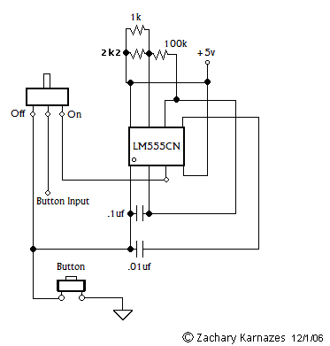
sven, just use this schematic and the autofire will be perfect:
http://i18.photobucket.com/albums/b134/ ... rSchem.png
matt- they work perfect but you need to build one for each button or use another circuit to send the same pulse to all the buttons without interfering. I doubt the NES had *just* a 555 for ALL button autofire. My guess is there is additional stuff in there.
It's not really much of a problem imo though, I only need autofire for the A (shot) button anyway.
-Segasonicfan
-
Dave_K.
- Posts: 4571
- Joined: Wed Jan 26, 2005 5:43 am
- Location: SF Bay Area
- Contact:
Thanks segasonicfan! What rate does this fire at? I thought you mentioned a potentiometer in there to regulate the speed, but I don't see it in the schematic.segasonicfan wrote: http://i18.photobucket.com/albums/b134/ ... rSchem.png
-
segasonicfan
- Posts: 456
- Joined: Tue Jul 04, 2006 5:20 am
- Contact:
yeah, you can add one if you want. I never had any need tho since it has functioned perfectly for all my games so far. I don't remember the speed for it but you can find out through the formulas online for the timer. It never really mattered to me, I just tested it enough to make sure the pulse was solid/perfect. I compared it with metal slug against the one programmed by the unibios and it works exactly the same. Ive thrown all my shooters PCBs at it and have had nothing but great results.
So yeah, sorry I can't give you more technical details as it has been a while since I designed it, but if I can find the site with the formulas later I will link it here. irc, you should be able to make one of those resistors a pot to change the frequency easily, I just forget which one >_<
fyi, the circuit works by using the button to provide grounding power. This isn't necessary for testing purposes. Pin 3 is the output and Pin 4 is ground. when the switch is thrown the output goes to the button which is activated when the circuit is grounded (button pressed).
-Segasonicfan
-
rtw
- Posts: 1959
- Joined: Wed Jan 26, 2005 6:46 pm
- Location: Norway
- Contact:
I am guessing the potentiometer can be added in the 2k2,1k 100k section.segasonicfan wrote:yeah, you can add one if you want. I never had any need tho since it has functioned perfectly for all my games so far. I don't remember the speed for it but you can find out through the formulas online for the timer. It never really mattered to me, I just tested it enough to make sure the pulse was solid/perfect. I compared it with metal slug against the one programmed by the unibios and it works exactly the same. Ive thrown all my shooters PCBs at it and have had nothing but great results.
So yeah, sorry I can't give you more technical details as it has been a while since I designed it, but if I can find the site with the formulas later I will link it here. irc, you should be able to make one of those resistors a pot to change the frequency easily, I just forget which one >_<
fyi, the circuit works by using the button to provide grounding power. This isn't necessary for testing purposes. Pin 3 is the output and Pin 4 is ground. when the switch is thrown the output goes to the button which is activated when the circuit is grounded (button pressed).
The circuit is a bit weird since the two resistors in parallel will yield
687ohms ? So a 680R from the E12 range should suffice.
Does anyone have the schematics for a circuit which can generate
a coin pulse ? I have a coin button on my cab and if I hold it down
to long I get a coin error on some games. ideally what I want is a
short pulse to be generated regardless of how long I hold down the
button.
rtw
http://world-of-arcades.net
The future of ST-V rests upon our work and your work
The future of ST-V rests upon our work and your work
-
D

- Posts: 3852
- Joined: Tue Feb 01, 2005 3:49 pm
- Location: Almere, Netherlands
- Contact:
-
matt
- Posts: 614
- Joined: Mon May 09, 2005 5:46 am
- Location: Honolulu, Hawaii
Indeed it did. Aside from a couple of resistors & capacitors, of course.segasonicfan wrote:I doubt the NES had *just* a 555 for ALL button autofire. My guess is there is additional stuff in there.
I notice that you use your 555 circuit on the signal side of the button. Why is that? If you put it on the ground side, the circuit is much simpler and you can hook up as many buttons as you want.
-
segasonicfan
- Posts: 456
- Joined: Tue Jul 04, 2006 5:20 am
- Contact:
ah, yes I forgot about this. The original design was using the 1k but I noticed the pulse wasnt perfect so I slapped on the other resistor. but you are correct, one 680ohm should suffice.The circuit is a bit weird since the two resistors in parallel will yield
687ohms ? So a 680R from the E12 range should suffice.
very interesting...could you possibly supply a pic/schematic?Indeed it did. Aside from a couple of resistors & capacitors, of course.
Im not sure what you mean...explain?I notice that you use your 555 circuit on the signal side of the button. Why is that? If you put it on the ground side, the circuit is much simpler and you can hook up as many buttons as you want.
-Segasonicfan
-
matt
- Posts: 614
- Joined: Mon May 09, 2005 5:46 am
- Location: Honolulu, Hawaii
It's around somewhere, but most of my electronics stuff is packed away and I don't have it handy. I'll post it if I find it.segasonicfan wrote:very interesting...could you possibly supply a pic/schematic?
The idea is to switch the button's regular ground lead with the oscillating high/low signal from the 555. All of the buttons are normally wired to a common ground, which is the same as connecting multiple buttons to the autofire signal.Im not sure what you mean...explain?I notice that you use your 555 circuit on the signal side of the button. Why is that? If you put it on the ground side, the circuit is much simpler and you can hook up as many buttons as you want.
-
Michaelm

- Posts: 1091
- Joined: Mon Sep 12, 2005 1:13 am
- Location: Western ignorant scum country
Could you be bothered to draw up a simple schematic to show how it all would be wired up with extra buttons ?matt wrote:The idea is to switch the button's regular ground lead with the oscillating high/low signal from the 555. All of the buttons are normally wired to a common ground, which is the same as connecting multiple buttons to the autofire signal.
A picture says more than a thousand words you know
All errors are intentional but mistakes could have been made.
-
segasonicfan
- Posts: 456
- Joined: Tue Jul 04, 2006 5:20 am
- Contact:
ah, I realized this a short while after I posted. My brain is just mush the first thing I wake up which is when I posted lastThe idea is to switch the button's regular ground lead with the oscillating high/low signal from the 555. All of the buttons are normally wired to a common ground, which is the same as connecting multiple buttons to the autofire signal.
That definitely makes a lot of sense, I'm surprised that didn't occur to me before (I feel like a complete idiot). Such an ovious way to make autofire for as many buttons as you like...! I do wonder what resistor/cap values that pad uses though. The values I use seem to give a perfect result but it never hurts to know what others thought up.
True, I can draw one up this weekend if nobody else wants to. Basically it's the exact same thing as t he schem I posted with matt's suggestion- just feed the pin 3 output of the 555 to the button's ground. Simple on/off switch and voila. Man I feel stupid for not thinking of that beforeCould you be bothered to draw up a simple schematic to show how it all would be wired up with extra buttons ?
A picture says more than a thousand words you know
-Segasonicfan
-
viletim
- Posts: 565
- Joined: Mon Aug 07, 2006 6:44 am
- Location: Sydney, Australia
- Contact:
Try mine if you like:does anyone have any tips for a stable circuit? (i already have a shitty one)
http://members.optusnet.com.au/eviltim/ ... dfire.html
I designed it to be retrofitted into a control panel I'd already built. It used a wire matrix instead of the standard common ground setup that's more typicaly used. I can draw up a common ground only version (fewer parts) if there's any interest.
The main problem with 555 based rapid fire is if you make it variable (add a pot), the adjustment is logarithmic (unresponsive on one end, super sensitive on the other), not linear.
-
segasonicfan
- Posts: 456
- Joined: Tue Jul 04, 2006 5:20 am
- Contact:
-
oxtsu

- Posts: 966
- Joined: Tue Jan 25, 2005 10:14 pm
- Location: USA - Oklahoma City
"555 is dead"
http://joysticktroopers.com/files/rapid ... ech_03.jpg
http://joysticktroopers.com/files/rapid ... tech04.jpg
u HOTLINK, u DIE
----------------------------------
For the JAMMA pcb type like Sanwa MGM-SS2, check out Tops. They have something similar in stock. It doesn't have the oh-so-pimp mirror of button1 like MGM had though... better suited for fighting games and old school stg's w/o a multi function button1.
-
rtw
- Posts: 1959
- Joined: Wed Jan 26, 2005 6:46 pm
- Location: Norway
- Contact:
Nice oxtsuoxtsu wrote:"555 is dead"
http://joysticktroopers.com/files/rapid ... ech_03.jpg
http://joysticktroopers.com/files/rapid ... tech04.jpg
u HOTLINK, u DIE
----------------------------------
For the JAMMA pcb type like Sanwa MGM-SS2, check out Tops. They have something similar in stock. It doesn't have the oh-so-pimp mirror of button1 like MGM had though... better suited for fighting games and old school stg's w/o a multi function button1.
rtw
http://world-of-arcades.net
The future of ST-V rests upon our work and your work
The future of ST-V rests upon our work and your work
-
zakk
- Posts: 1410
- Joined: Wed Jan 26, 2005 6:04 am
- Location: New York, NY
- Contact:
-
matt
- Posts: 614
- Joined: Mon May 09, 2005 5:46 am
- Location: Honolulu, Hawaii

-
viletim
- Posts: 565
- Joined: Mon Aug 07, 2006 6:44 am
- Location: Sydney, Australia
- Contact:

-
sven666
- Posts: 4545
- Joined: Wed Feb 02, 2005 2:04 am
- Location: sweden
- Contact:
FINALLY!
http://www.youtube.com/watch?v=JTNI7G_I9DE
got this little baby off yahoo, holy shit is it simple!
http://www.youtube.com/watch?v=JTNI7G_I9DE
got this little baby off yahoo, holy shit is it simple!
the destruction of everything, is the beginning of something new. your whole world is on fire, and soon, you'll be too..
-
cools

- Posts: 2057
- Joined: Mon Nov 26, 2007 4:57 pm
- Location: South Wales
- Contact:
Thread, rise from your gravesven666 wrote:FINALLY!
http://www.youtube.com/watch?v=JTNI7G_I9DE
got this little baby off yahoo, holy shit is it simple!
Anyone got any idea how to build one like this?