another question:
could someone compare the height of the Seimetsu and Sanwa stick to the stock DC Agetech stick?
im not sure which size i want to go with. thanks.
Another DC/Sanwa modded stick
-
oxtsu

- Posts: 966
- Joined: Tue Jan 25, 2005 10:14 pm
- Location: USA - Oklahoma City
-
SAM

- Posts: 1788
- Joined: Fri Jun 03, 2005 5:27 am
- Location: A tiny nameless island in South China Sea
Hey guys, I have been wondering how you unscrew those screws (star sharp headed) holding the upper most plate of the DC Agetac joystick for quite a while. 
 What kind of bit are you using? Where can you found the bit?
I am trying to unscaw those screws for quite a while but failed...
I am trying to unscaw those screws for quite a while but failed...
*Meow* I am as serious as a cat could possible be. *Meow*
-
oxtsu
- Posts: 966
- Joined: Tue Jan 25, 2005 10:14 pm
- Location: USA - Oklahoma City
-
Daigoro

- Posts: 235
- Joined: Sat Aug 20, 2005 2:34 pm
- Location: CT/US
thanks for the measurements oxtsu, that helps.
edit: ok i did find a bunch of info on shoryuken forums, thanks.
can you repost that link to the Japanese page again Gaijin? i cant find it.
GaijinPunch wrote:Diagoro:
go to the shoryuken.com forums (hardware). There's mountains of information in there. That's where I got just about everything. Match that with the information in the link I posted above (the Japanese page). H
edit: ok i did find a bunch of info on shoryuken forums, thanks.
can you repost that link to the Japanese page again Gaijin? i cant find it.
-
Daigoro
- Posts: 235
- Joined: Sat Aug 20, 2005 2:34 pm
- Location: CT/US
hi. just wanted to leave an update to say that things are going very well with my Sanwa mod.
i received the parts and prepped the case and top plate yesterday.
all thats left is to pop in the buttons and stick, and then wire it all. should be done in a few hours, assuming no complications pop up.
hopefully ill be able to borrow a camera to post som pics up.
thanks a bunch for the help and inspiration in this thread. ive been meaning to do this for awhile now, but this thread really got me off my ass to really start the work. (Tychom your page helped a ton)
cant wait to try out some shmups and VF4 on my new stick!
-
Daigoro
- Posts: 235
- Joined: Sat Aug 20, 2005 2:34 pm
- Location: CT/US
well i know its a year later, but i finally took a pic of my Agetec mod.
thanks again to everyone in this thread that helped and to GaijinPunch who made the thread that really inspired me to finally go ahead and try my first mod.
it's a damn easy mod. hopefully this will help inspire someone else to try it out.
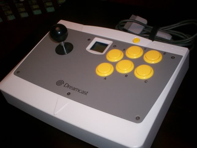
all Sanwa (got the parts from Himura), it still works like a charm. i think ill go play some Under Defeat.
thanks again to everyone in this thread that helped and to GaijinPunch who made the thread that really inspired me to finally go ahead and try my first mod.
it's a damn easy mod. hopefully this will help inspire someone else to try it out.
all Sanwa (got the parts from Himura), it still works like a charm. i think ill go play some Under Defeat.
-
KBZ
- Posts: 1257
- Joined: Sat Mar 26, 2005 4:47 am
looks sexy, interesting choice of colours.
I have a sanwa stick modded agetec that's spliced for dc and db15 vga port. I also wired a db15 vga ---> psx dual shock box.
I'm waiting for it all to be shipped out to me since I've just moved to vancouver, I'll take some pictures of it then.
Unfortunately I didn't put it a switch to go from db15 to dc so I need to unplug the dc pcb everytime I want to play ps2.
later,
King.
=/
-
Mikey
- Posts: 166
- Joined: Thu May 04, 2006 7:47 pm
Unplug it from what - The Dreamcast controller port?Kingbuzzo wrote: Unfortunately I didn't put it a switch to go from db15 to dc so I need to unplug the dc pcb everytime I want to play ps2.
What measures to you have to take then to disable the Dreamcast side of the stick from the DB-15 when playing through the DB-15?
-
Daigoro
- Posts: 235
- Joined: Sat Aug 20, 2005 2:34 pm
- Location: CT/US
thanks. yeah, i wanted to do 3 black and 3 yellow buttons, but of course Sanwa dosent make black buttons! (actually the guy from Akibara shop was trying to work out a deal with Sanwa to get them to produce some at some point... maybe one day).Kingbuzzo wrote:looks sexy, interesting choice of colours.
i actually got the parts from Himura and Rod also includes a purple clear sparkly ball top that i just changed out before i took these pics. it didnt look to bad actually, but wasnt my originally intended color scheme.
i want to mod my other Agetec with a db15 and make some project boxes for all of my systems. hopefully ill start that project this year. need a dremmel for that though!
(sorry i cant answer your question Mikey, not sure how King has his stick set up. ive never even wired a db15 before).
-
oxtsu
- Posts: 966
- Joined: Tue Jan 25, 2005 10:14 pm
- Location: USA - Oklahoma City
The encoder PCB inside the Agetec is attached by harness to the controls, so he just unplugged them when using PS2. This is a hassle though. The way to do it is remove the encoder, put in a seperate case, and wire to a DB-15 connector. Another would be to install a switch that cuts off GROUND from the DC encoder, but it's not that effective in my experience.Mikey wrote:Unplug it from what - The Dreamcast controller port?Kingbuzzo wrote: Unfortunately I didn't put it a switch to go from db15 to dc so I need to unplug the dc pcb everytime I want to play ps2.
What measures to you have to take then to disable the Dreamcast side of the stick from the DB-15 when playing through the DB-15?
-
GaijinPunch

- Posts: 15954
- Joined: Mon Jan 31, 2005 11:22 pm
- Location: San Fransicso
-
CIT

- Posts: 4692
- Joined: Thu Jun 30, 2005 2:39 pm
- Location: Germany
- Contact:
-
GaijinPunch
- Posts: 15954
- Joined: Mon Jan 31, 2005 11:22 pm
- Location: San Fransicso
-
Mikey
- Posts: 166
- Joined: Thu May 04, 2006 7:47 pm
Or I guess you could leave the DC stick's PCB and VMU slot where they are and run the DC's stick and button wires out through the case to a DB15. It would mean having a DB15 dangling from the case when not in use as a DC stick but at least you keep the VMU slot and don't have a VMU dangling from the project box.oxtsu wrote:The encoder PCB inside the Agetec is attached by harness to the controls, so he just unplugged them when using PS2. This is a hassle though. The way to do it is remove the encoder, put in a seperate case, and wire to a DB-15 connector. Another would be to install a switch that cuts off GROUND from the DC encoder, but it's not that effective in my experience.Mikey wrote:Unplug it from what - The Dreamcast controller port?Kingbuzzo wrote: Unfortunately I didn't put it a switch to go from db15 to dc so I need to unplug the dc pcb everytime I want to play ps2.
What measures to you have to take then to disable the Dreamcast side of the stick from the DB-15 when playing through the DB-15?


-
fubarduck
- Posts: 41
- Joined: Fri Jul 28, 2006 3:57 pm
Sorry to bump an old thread, but I finally figured out how you can have a Dreamcast/Playstation/whatever PCB hooked up internally in the Agetec mod with a DB-15 port at the same time with no interference! That means you can have both a Dreamcast/Playstation cord with a seperate DB15 port hooked up at all times, without the need to make external adapters with your Dreamcast or Playstation PCB.
First, you have to seperate the common ground with a switch. Any 3 prong SPST switch should be fine. Hook the joystick and button grounds up to the middle terminal, then solder the Dreamcast/PSX PCB grounds to one end and the DB15 ground to the other.
Secondly, and here's the part I couldn't figure out for a long time, you MUST hook the +5v wire from the DB15 port to the +5v or +3.3v on your Playstation/Dreamcast PCB! IF you don't do this, you will get random button inputs and directional presses. It will vary how much it freaks out depending on what you're doing with the DB15 port, but it will never be perfect.
Even with the grounds seperated, there will always be some interference from the Dreamcast/PSX PCB. In a nutshell, there are some capacitors on it that freak out when the button's circuits are closed and it isn't getting any resistance voltage to even it out. Give it power, though, and viola, problem solved (as long as the grounds are seperate)! Of course, you risk frying the PCB if you ever plug in the Supergun and Dreamcast/PSX cord at the same time, so, uhh, don't do it.
So here's how my Agetec is hooked up now: I have a PSX PCB wired to the bottom of the female molex connector on the Dreamcast PCB. The molex connectors plug into the Dreamcast PCB to connect everything.
One wire connects the +3.3v to the +5v point on the Playstation PCB, since the Playstation cord won't work otherwise (again, the DC PCB MUST be powered if you're wiring through it). Grounds are shared on these PCBs though with no problem.
Then, the DB15 is wired seperately to the buttons/joystick. So basically, I have two wires that hook up to each button terminal on one end, and a common ground on the other end (which is connected through a switch).
Pictures are clearer than words, so here's a Flickr photo as well:
http://www.flickr.com/photos/58078637@N00/265545421/
(Note that this was before I connected +5v from the DB15 to the +3.3v on the Dreamcast PCB).
Also, it may bother some people that the +5v will be TOO MUCH and fry the Dreamcast PCB, but I assure you it will be fine as long as you don't plug in both cords and power multiple systems at the same time.
Hope this helps someone eventually, as it made my Agetec mods very convenient!
-
tassian

- Posts: 63
- Joined: Sun Dec 10, 2006 11:54 am
-
fubarduck
- Posts: 41
- Joined: Fri Jul 28, 2006 3:57 pm
OK. Here's the deal if you just want to use DC/PSX.tassian wrote:I would also like to mod my DC stick with both a DC and a PSX PCB (no DB15, though) as well. I have one question regarding this setup: is is sufficient to just have the "common ground switch" in this setup or do I need to connect +3.3V on the two PCBs?
Since the DC needs +3.3V and the PSX needs +5V, you MIGHT need a switch to change between DC and PSX mode (DC +3.3v on one terminal, PSX +5v on the opposite terminal). I don't use Dreamcast at all on my Agetecs, so I'm not 100% sure. You can definitely share the ground among the PCBs though no problem.
So, first try connecting a wire from +3.3v to the Dreamcast PCB to +5v on the Playstation PCB. What should happen is, the Playstation half should work fine. The Dreamcast half, I'm not sure--but you can easily add a switch to make DC work also if it doesn't.
-
tassian
- Posts: 63
- Joined: Sun Dec 10, 2006 11:54 am
Thanks for the heads up. I'll have a look at the controller primers at GameStationX and throw in a switch just to be sure.
Don't drink and Ikaruga!
-
tassian
- Posts: 63
- Joined: Sun Dec 10, 2006 11:54 am
Hm, I encountered a problem: I used a model A PS2 controller to mod my DC stick. Contrary to most instructions I found on modding the model A PS2 controller, mine has connector on the controller PCB with 18 contacts instead of 16. What I found was that the d-pad and all buttons except for "Start", "Analog", and "Select" have one common contact which is obviously GND. Unfortunately, there's an additional common contact for "Start", "Analog", and "Select". I assumed that it's also GND but on the PCB, the potential GNDs for d-pad and buttons are not connected. Furthermore there's an additonal line which leads to an unused button on the contact foil. Basically, when I wire the PCB to the buttons (I also have a three pole switch to separate GND of the PS2 controller PCB and the DC controller PCB), the LED, which indicates that Analog is active, is lit but the buttons and the stick don't work. I'm 100% sure there's nothing shorted (I used a multimeter to confirm that). Do you have an idea what went wrong? I also confirmed that all button presses and joystick movements close the correct contacts on the PS2 PCB. Every advice / hint is highly appreciated.
Don't drink and Ikaruga!
-
fubarduck
- Posts: 41
- Joined: Fri Jul 28, 2006 3:57 pm
Like I said in my previous post, you MUST have a switch to go between +3.3v on the DC PCB and +5v on the PSX PCB. YOU DO NOT NEED TO SEPERATE THE GROUNDS unless you are adding a DB-15 for NeoGeo/Supergun usage. Cut the wires on your switch, and put 3.3v from the DC PCB on one pole and +5v from the PSX PCB on the opposite pole, and your problem will be solved.tassian wrote:Hm, I encountered a problem: I used a model A PS2 controller to mod my DC stick. Contrary to most instructions I found on modding the model A PS2 controller, mine has connector on the controller PCB with 18 contacts instead of 16. What I found was that the d-pad and all buttons except for "Start", "Analog", and "Select" have one common contact which is obviously GND. Unfortunately, there's an additional common contact for "Start", "Analog", and "Select". I assumed that it's also GND but on the PCB, the potential GNDs for d-pad and buttons are not connected. Furthermore there's an additonal line which leads to an unused button on the contact foil. Basically, when I wire the PCB to the buttons (I also have a three pole switch to separate GND of the PS2 controller PCB and the DC controller PCB), the LED, which indicates that Analog is active, is lit but the buttons and the stick don't work. I'm 100% sure there's nothing shorted (I used a multimeter to confirm that). Do you have an idea what went wrong? I also confirmed that all button presses and joystick movements close the correct contacts on the PS2 PCB. Every advice / hint is highly appreciated.
Alternately, if you have no intention of using the Dreamcast part of the controller, you can connect a wire directly from +3.3v on the DC PCB to +5v on the PSX PCB (which is what I did; I don't use my Agetecs for Dreamcast, I simply did my wiring through the DC PCB for convenience purposes).
-
thchardcore
- Posts: 498
- Joined: Wed Jun 22, 2005 9:20 am
- Location: Liberal cesspool
What fubar is saying is that you must locate the 3.3-5 wire running from the cord to the pcb and cut it. You will wire each of these to a leg on a DPST switch. Next, look at the spot where you cut each wire from the pcb. Solder a wire from that point to the center of the switch on both pcbs. Wiring through the dc pcb is idiotic though and shows your lack of knowledge with electronics, I'm sorry to say. Doing this can only create problems with ground and can give you weird signal output, please dont do this. Also, why on earth you would need a seperate ground for neo-geo/jamma use for a supergun is beyond me. Ground is ground with very few exceptions, this is incorrect. Use diodes on each ground f you are worried about signal problems. Never plug both in at the same time (well you can) but don't do it, you'll have issues.fubarduck wrote:Like I said in my previous post, you MUST have a switch to go between +3.3v on the DC PCB and +5v on the PSX PCB. YOU DO NOT NEED TO SEPERATE THE GROUNDS unless you are adding a DB-15 for NeoGeo/Supergun usage. Cut the wires on your switch, and put 3.3v from the DC PCB on one pole and +5v from the PSX PCB on the opposite pole, and your problem will be solved.tassian wrote:Hm, I encountered a problem: I used a model A PS2 controller to mod my DC stick. Contrary to most instructions I found on modding the model A PS2 controller, mine has connector on the controller PCB with 18 contacts instead of 16. What I found was that the d-pad and all buttons except for "Start", "Analog", and "Select" have one common contact which is obviously GND. Unfortunately, there's an additional common contact for "Start", "Analog", and "Select". I assumed that it's also GND but on the PCB, the potential GNDs for d-pad and buttons are not connected. Furthermore there's an additonal line which leads to an unused button on the contact foil. Basically, when I wire the PCB to the buttons (I also have a three pole switch to separate GND of the PS2 controller PCB and the DC controller PCB), the LED, which indicates that Analog is active, is lit but the buttons and the stick don't work. I'm 100% sure there's nothing shorted (I used a multimeter to confirm that). Do you have an idea what went wrong? I also confirmed that all button presses and joystick movements close the correct contacts on the PS2 PCB. Every advice / hint is highly appreciated.
Alternately, if you have no intention of using the Dreamcast part of the controller, you can connect a wire directly from +3.3v on the DC PCB to +5v on the PSX PCB (which is what I did; I don't use my Agetecs for Dreamcast, I simply did my wiring through the DC PCB for convenience purposes).
Also, you can credit ShinACE from the SRK forums (from which you are loved) for being the first to my knowledge to provide such information.
Class dismissed.
A camel is a horse designed by a committee
-
fubarduck
- Posts: 41
- Joined: Fri Jul 28, 2006 3:57 pm
Silly reasoning, but the other reason I wired through the DC PCB was so that it would make the VMU beeping sound when I plugged it into a PS2. We always joked around that the VMU slot shouldn't just go to waste (and I don't use/play DC at all anyway). Not saying other people should do the wiring this way, but it's entirely possible and causes no harm to any of the systems nor does it damage the PCBs.thchardcore wrote: What fubar is saying is that you must locate the 3.3-5 wire running from the cord to the pcb and cut it. You will wire each of these to a leg on a DPST switch. Next, look at the spot where you cut each wire from the pcb. Solder a wire from that point to the center of the switch on both pcbs. Wiring through the dc pcb is idiotic though and shows your lack of knowledge with electronics, I'm sorry to say. Doing this can only create problems with ground and can give you weird signal output, please dont do this. Also, why on earth you would need a seperate ground for neo-geo/jamma use for a supergun is beyond me. Ground is ground with very few exceptions, this is incorrect. Use diodes on each ground f you are worried about signal problems. Never plug both in at the same time (well you can) but don't do it, you'll have issues.
Also, you can credit ShinACE from the SRK forums (from which you are loved) for being the first to my knowledge to provide such information.
Class dismissed.
At first I didn't put +5v from the Supergun to the DC/PSX PCBs, so if grounds were not seperated from PSX/DC, the DB15/Supergun output would go haywire (random button presses/joystick inputs) but since I added the +5v everything works perfectly on the DB15 end and I might not even need a switch to seperate the grounds anymore, I'm not sure but I already have them installed and they don't hurt anything so I haven't removed them.
Again I am not an electrician or engineer, just a gamer with some very basic electronics knowledge, I get my engineer friend to help with what I can't figure out. This is what works for me, and there are certainly alternatives but I have zero problems using my modded Agetecs on PS2/PS3/Supergun without the hassle of needing external DB15-based adapters for every system.
-
Fudoh

- Posts: 13044
- Joined: Mon Mar 06, 2006 3:29 am
- Location: Germany
- Contact:
I have a small question for those who have modded a DC stick. I would like to swap the stick and the buttons in mine with Seimitsu parts, but keep it for DC usage only. I'm just wondering if there're any changes to the chassis neccessary (like drilling new holes or melting away plastic...).
Thanks in advance !
Thanks in advance !