Hopefully someone here has one of these and can help. I have an Otaku 6 Port SCART switch that I use with my CRT gaming setup. (https://otaku-games.com/6-port-rgb-scart-switch.html). On the board there's a little switch that selected In or Out which needs to be in the IN position for the switch to work properly with my setup. Unfortunately this little switch completely broke off while I was adjusting something (completely my fault). Looking at that switch it seems simple enough, it just has some little metal clips that appear to bridge the two rows of 'teeth' on the board. I can probably just bridge these with a solder blob or wire, but I have no idea which 'teeth' need to be bridged for IN.
Does anyone here have an Otaku 6 Port switch that can check which tabs need to be bridged? I'd hate to have to buy a whole new switch for something that's most likely an easy repair, but without knowing what needs to be bridged to what I might have to. Note that there were four sets of those metal tabs that went into the switch originally, but I somehow manged to lose two of them. Spoiler
Last night as I was looking at the physical layout of the switch I had come to the same conclusion but I wanted to be sure before I tried soldering anything.
Actually, can you buy this type of switch anywhere? It might be easier to try and fix the switch than to bodge it.
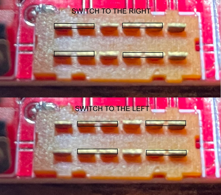
Wait are you sure about that? It seems backwards from what I'm seeing. It appears that if the switch is to the left the black plastic that holds the little metal clips is all the way left and there's a gap on the right side and vice versa.
Sounds exactly backwards to me. It would be physically moving metal jumpers to the left when moved left, leaving a gap on the far right, don't see how it would mechanically make sense to invert those movements. Switches are dumb and cheap, I guess theoretically moving it left could jumper pins to the right but why complicate things.
The switch linked also looks like a 4-position, which would be incorrect.
bobrocks95 wrote:Sounds exactly backwards to me. It would be physically moving metal jumpers to the left when moved left, leaving a gap on the far right, don't see how it would mechanically make sense to invert those movements. Switches are dumb and cheap, I guess theoretically moving it left could jumper pins to the right but why complicate things.
The switch linked also looks like a 4-position, which would be incorrect.
Right I noticed that too. So it sounds like if I want the switch left then I need to bridge the first two pins and the fourth and fifth pin leaving the third and sixth pins alone.