JVC 36" AV36850 RGB mux Mod / TA1242N Jungle / New Mod Video

The place for all discussion on gaming hardware
deezdrama
Posts: 222
Joined: Sat Dec 21, 2019 4:10 pm

Re: JVC Big Bertha AV36850/ RGB Mod / TA1242N Jungle

Post by deezdrama »

Rgb cutoff settings are only in the "theatre" picture mode settings of serv menu. I can set them high and get a little boost in brightness and vibrancy but black levels get washed out, so i turn down g2 to get black blacks and its all dim again like square one.

There is a white balance high and white balance low setting in serv menu. Im able to boost r g and b to the moon if i want, ive turned them up so high that the osd letters were bleeding everywhere, then adjust g2 to get black levels black and its same dim picture.

Its like stealing from one glass of water and pouring it in the other trying to get more water but you always have same amount.

Spent hours messing with it. I just dont think there is any gains to be made :cry:
MarkOZLAD
Posts: 1021
Joined: Thu May 18, 2017 12:39 pm

Re: JVC Big Bertha AV36850/ RGB Mod / TA1242N Jungle

Post by MarkOZLAD »

Do you want to try a different RGB level?
___________________________________________________
MarkOZLAD
OSD/External RGB Mux Diagram
OSD/External RGB Mux Resistor Value Table 0.7Vp-p : 0.5Vp-p

"Imagine toggle switch OSD modding a TV in 2019" - maxtherabbit
deezdrama
Posts: 222
Joined: Sat Dec 21, 2019 4:10 pm

Re: JVC Big Bertha AV36850/ RGB Mod / TA1242N Jungle

Post by deezdrama »

MarkOZLAD wrote:Do you want to try a different RGB level?
Sure, If you have an idea im willing to try it.
I could set everything in service menu back to default and set the g2 back to factory level.
If we can feed a stronger rgb level maybe I can clean it up then with cutoffs and g2?
MarkOZLAD
Posts: 1021
Joined: Thu May 18, 2017 12:39 pm

Re: JVC Big Bertha AV36850/ RGB Mod / TA1242N Jungle

Post by MarkOZLAD »

If you want to try the standard 0.7Vp-p..

Remove 24R attenuation resistor
Replace 51R with 75R
The 620R mux resistor likely fine but could swap it for a 560R if OSD bleeds.

I've heard some say it's a 1Vp-p. This is weird but given your current results...

Remove 24R attenuation resistor
Replace 51R with 180R
Replace 620R mux resistor with 510R or 470R

Good luck
___________________________________________________
MarkOZLAD
OSD/External RGB Mux Diagram
OSD/External RGB Mux Resistor Value Table 0.7Vp-p : 0.5Vp-p

"Imagine toggle switch OSD modding a TV in 2019" - maxtherabbit
deezdrama
Posts: 222
Joined: Sat Dec 21, 2019 4:10 pm

Re: JVC Big Bertha AV36850/ RGB Mod / TA1242N Jungle

Post by deezdrama »

MarkOZLAD wrote:If you want to try the standard 0.7Vp-p..

Remove 24R attenuation resistor
Replace 51R with 75R
The 620R mux resistor likely fine but could swap it for a 560R if OSD bleeds.

I've heard some say it's a 1Vp-p. This is weird but given your current results...

Remove 24R attenuation resistor
Replace 51R with 180R
Replace 620R mux resistor with 510R or 470R

Good luck
Awesome man....many thanks!
This will give me a reason to replace that one cap and do this at same time
deezdrama
Posts: 222
Joined: Sat Dec 21, 2019 4:10 pm

Re: JVC Big Bertha AV36850/ RGB Mod / TA1242N Jungle

Post by deezdrama »

MarkOZLAD wrote:If you want to try the standard 0.7Vp-p..

Remove 24R attenuation resistor
Replace 51R with 75R
The 620R mux resistor likely fine but could swap it for a 560R if OSD bleeds.

I've heard some say it's a 1Vp-p. This is weird but given your current results...

Remove 24R attenuation resistor
Replace 51R with 180R
Replace 620R mux resistor with 510R or 470R

Good luck

Went straight for 1v
180ohm termination, 510ohm mux

VICTORY!!!!!

Absolutely jaw dropping perfect!
Only had to tweek g2 to set brightness, rgb levels and contrast are perfect!

I have over a dozen pvm/pro/broadcast monitors and I can easily say this is tied for the number one spot of favorite crt along side my 20" Panasonic 800tvl broadcast monitor!

Neo Geo and arcade content look fantastic like a giant arcade tube in my room!
Was definitely worth the troubles!

Image

Image

Image

Image

Image

Image

Image

Image

Image


Pics truely do this tube no justice!
Super happy it turned out better than expected!
Thanks again Mark!


MarkOZLAD
Posts: 1021
Joined: Thu May 18, 2017 12:39 pm

Re: JVC Big Bertha AV36850/ RGB Mod / TA1242N Jungle

Post by MarkOZLAD »

Looks fantastic. I’ll update my diagram.
___________________________________________________
MarkOZLAD
OSD/External RGB Mux Diagram
OSD/External RGB Mux Resistor Value Table 0.7Vp-p : 0.5Vp-p

"Imagine toggle switch OSD modding a TV in 2019" - maxtherabbit
MarkOZLAD
Posts: 1021
Joined: Thu May 18, 2017 12:39 pm

Re: JVC Big Bertha AV36850/ RGB Mod / TA1242N Jungle

Post by MarkOZLAD »

Original diagrams updated on page one
___________________________________________________
MarkOZLAD
OSD/External RGB Mux Diagram
OSD/External RGB Mux Resistor Value Table 0.7Vp-p : 0.5Vp-p

"Imagine toggle switch OSD modding a TV in 2019" - maxtherabbit
deezdrama
Posts: 222
Joined: Sat Dec 21, 2019 4:10 pm

Re: JVC Big Bertha AV36850/ RGB Mod / TA1242N Jungle

Post by deezdrama »

Youtube video of the mod is done. Wish my lumix g85 played better with crt footage :(

https://youtu.be/OBiB3B4Z0qs
deezdrama
Posts: 222
Joined: Sat Dec 21, 2019 4:10 pm

Re: JVC 36" AV36850 RGB mux Mod / TA1242N Jungle / New Mod V

Post by deezdrama »

Ok, so just upgraded my mister fpga with digital audio to a soundbar and sub..... Decided to connect my 20" panasonic 800tvl broadcast crt monitor to mister and output rgb from it to the 36" jvc beast.

Seeing them side by side I realized how off the colors were on the jvc
Image


I decided to calibrate the rgb levels as best as I could using my eyeballs and 240p test suite color bars.

Here are my options for this jvc set
Image

Image


There is rgb drive levels under the "theater" mode section of the service menu. Theater mode is just a picture preset like "vibrant" or "movie" presets but nomatter how much I messed with theater mode settings I just think theater mode looks like crap so reverted its settings back to the default values.

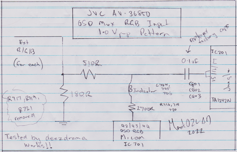
Remember..... This rgb muxing on this jungle leaves the basic brightness,contrast,etc unuseable for the rgb signal, although 1vpp mux brings the rgb levels to a good level and image.... I need to adjust the individual colors to balance and calibrate the image......

So im left with only 2 options in the service menu as far as I can tell.....
" High light" with G drive and B drive options

Or "Low light with R G B cutoffs


It seems I get the best adjustments in "Low light" settings and setting

R cutoff from factory 20 to 125
G cutoff from factory 20 to 125
B cutoff from factory 20 to 145

It makes sense blue needed more since the no signal state on this crt uses a blue screen so blue wpuld probably be the first gun to start dropping in output.

Anyway I used the color bars in 240p test suite to bring all 3 colors to a better level.
Green was fine but red and blue were really low

Image


After bumping up the levels to get all 3 colors set right acording to the color bar user recommendations I get a much better image very close to my 20" broadcast crt

Image

Image


It looks great and was super happy with it but after 10-15 min of playing... A white screen triggered overvoltage protection

I turned down R B G cutoffs a hair after unplugging the set for a while.

Played for about an hour before the tv triggered overvoltage protection again .


This has me wondering how I should proceed.

Should i just turn down g2 a hair?
Turn down cutoffs a bit more?

Should I be messing with drive levels instead of cutoff levels?
The problem is there is only green and blue drive options, no red.

Any suggestions?
Thanks


Edit.......

So the initial fix that triggered overvoltage protection was R 125, G 125, B145..... Ive toned them down to R115,G115, B 125.... Not as vibrant but I kind of like it better. I probably should turn g2 down a hair but really dont want to open this beast back up. Sofar Ive played neo geo for about an hour and no overvolt, it just sucks knowing its right on the line of triggering it. The service manual mentions rgb drive and cutoffs used to set white balance levels..... I mean, it definitely corected the pureness of white by getting all 3 colors at the same output but confused why these rgb settings are labeled as for white balance adjustments. I been through the whole service menu, B and G drive didnt achieve anything close to what I needed so the cutoff settings were the only way I found to adjust the rgb levels. Does this seem right or is there a technical reason this is borderline of triggering overvoltage? I mean it makes sense im having to pump more output from each colors gun. At this point I wonder if re-muxing slightly higher than 1vpp would help?


Edit # 7453 lol

I ended up setting the rgb cutoff levels back to default and bumping up the g2 to get good levels on color bars. Blue again needed an extra little boost but all is looking great and sofar no issues. Even the symphony of the night screen that goes all white and triggered overvoltage protection is running fine now.

This is more of a personal log and for anyone maybe in the future who rgb mods one of these.

1vpp rgb mux, keep service menu at default and adjust g2 to get good levels without washing blacks out, tweek cutoffs if needed.
One of my fav tubes after rgb modding!
User avatar
matt
Posts: 615
Joined: Mon May 09, 2005 5:46 am
Location: Honolulu, Hawaii

Re: JVC 36" AV36850 RGB mux Mod / TA1242N Jungle / New Mod V

Post by matt »

deezdrama wrote:I probably should turn g2 down a hair but really dont want to open this beast back up.
Most of these JVCs have holes in the back for G2 and focus adjustment. Is yours not like this?
bartman2468
Posts: 2
Joined: Mon Oct 24, 2022 8:24 pm

Re: JVC 36" AV36850 RGB mux Mod / TA1242N Jungle / New Mod V

Post by bartman2468 »

I just picked up an AV-27950 that has the same jungle chip. I've been researching the rgb mod and came across this thread.

If I'm going to use this in an arcade cabinet, is a mux necessary? I read that it retains the OSD, but I assume that's not needed if I'm putting it in an arcade.

Just trying to keep it as simple as possible because I'm new to this and don't want to screw anything up.

I appreciate any info or help. Just for reference this is the service manual: https://diagramas.diagramasde.com/otros ... -27950.pdf

Someone on a Reddit thread mentioned 75 ohm terminating resistors on the source signal and then 440 ohm resistors from the signal to the rgb on the PIP module, but the guy tried that and it ended up being dim and he couldn't figure out how to fix it.

I wish I knew more about this stuff because this 27" jvc is perfect for an empty arcade cabinet I have.
deezdrama
Posts: 222
Joined: Sat Dec 21, 2019 4:10 pm

Re: JVC 36" AV36850 RGB mux Mod / TA1242N Jungle / New Mod V

Post by deezdrama »

matt wrote:
deezdrama wrote:I probably should turn g2 down a hair but really dont want to open this beast back up.
Most of these JVCs have holes in the back for G2 and focus adjustment. Is yours not like this?
Ill feel stupid if it does lol, Ill have to look
bartman2468
Posts: 2
Joined: Mon Oct 24, 2022 8:24 pm

Re: JVC Big Bertha AV36850/ RGB Mod / TA1242N Jungle

Post by bartman2468 »

MarkOZLAD wrote:RGB Mod instructions:

EDIT: Revised 1.0Vp-p diagram after deezdrama had tried 0.5Vp-p and failed.

Image
Image

For 1.0V p-p we need a 180 ohm termination resistor to maintain 1.0Vp-p RGB coming in.

(I won't bore you too much with the maths right now but it's basically something like 0.7 * 255/180 = 0.99... The RGB signal from the console is typically sent through a 75 ohm inline resistor.)

For the mux resistor we will cheat by subtracting 180 from the value of the factory grounding resistor (now removed) which was 680 ohm. This leaves as at 500 ohm, nearest standard resistor is 510 Ohm.

This makes the match of the OSD signal 5V * 690/3390 = 1.02V basically same as factory
Spoiler
0.5Vp-p????

The datasheet for the TA1242N suggests 0.5Vp-p RGB input but I cannot be sure. Unfortunately the datasheet is in Chinese and being Australian my Chinese is quite poor....

I've also read in the TV RGB Mod thread that it is 0.5Vp-p but I don't know exactly why they are saying that.

Let's examine the factory OSD circuitry. IC701 MN1874876JZX1 has 5V as it's Vdd. Thus I assume it's a 5V chip and will output 5V OSD. There factory voltage dividers on the OSD RGB uses a 2.7K ohm inline and 680 ohm to ground.

5V * 680 / (2700 + 680) = 1V (1.0059V)

I'm pretty sure I've seen other users that suggest it requires 1Vp-p....

I'm confused but let us first mod for 0.5Vp-p as a test and see how it goes. If it's no good we can revise.

OSD Mux Resistor Calculation

Let's cheat here. The existing OSD grounding resistor is 680 ohm. Because we are using the 0.5Vp-p pattern for termination we will have a termination resistor of 51 ohm. 680 - 51 = 629 ohm. A 620 ohm mux resistor shoud be close enough.

This would result in an OSD voltage of..

5V * (620 + 51) / (2700 + (620 + 51)) = 1V (0.99525V close enough to 1V for my liking)

If it's good enough for the factory it's good enough for me

Physical Mod
Ok, here we go

1) Remove SMD resistors R717, R719, R721 (factory OSD "grounding" resistors)
2) For blanking we want to go from a 5V source into a switch then into a 1.8K resistor and then onto jumper W019
3) For each of the RGB lines we want to bring the external RGB into a 24 ohm resistor and then 51 ohm to ground. Then for each run a line from between these two resistors onto the RGB jumpers into a 620 ohm resistor then onto their respective jumpers.
4) Replace caps C801, 802 and 803 with 0.1uF (104) ceramic caps

Image

Physical Mod
Ok, here we go

1) Remove SMD resistors R717, R719, R721 (factory OSD "grounding" resistors)
2) For blanking we want to go from a 5V source into a switch then into a 1.8K resistor and then onto jumper W019
3) For each of the RGB lines we want to bring in the external RGB, we want 180 ohm to ground. Then for each run a line from between these two resistors onto the RGB jumpers into a 510 ohm resistor then onto their respective jumpers.
4) Replace caps C801, 802 and 803 with 0.1uF (104) ceramic caps
I'm new to RGB mods. Would these values be different if I am using RGB output from a Jamma board? I read that jamma outputs between like 2 and 5vpp, whereas this mod seems to be designed for game console outputs. What would I need to consider when doing this? I have the same jungle chip in my 27" JVC av-27950, same series as this tv. Sorry for noob question. I appreciate any info you all have. Thanks
Santeegmc
Posts: 4
Joined: Sat Jun 01, 2024 3:22 pm

Re: JVC 36" AV36850 RGB mux Mod / TA1242N Jungle / New Mod Video

Post by Santeegmc »

Hello,
I'm working on the same mod but for a JVC AV36020.
It has the same TA1242N jungle chip, but the board layout seems to be different. Any chance I could get a pin layout diagram for this series?
gabrielgamer99
Posts: 4
Joined: Thu Sep 21, 2023 9:56 pm

Re: JVC 36" AV36850 RGB mux Mod / TA1242N Jungle / New Mod Video

Post by gabrielgamer99 »

Could somebody Explain the math on how the 180 was calculated, it doesn't make sense to me
I have a jvc sears tv with the same jungle chip and my image is dark like the tv in this one started out
My osd values are 4.7k and the ground ones I moved are 1.5k

Im trying to get values for 1vp-p on my tv.
Post Reply