Please save me from a centering circuit - RGB Trinitron

The place for all discussion on gaming hardware
Post Reply
halfspec
Posts: 9
Joined: Wed Dec 08, 2021 3:26 pm

Please save me from a centering circuit - RGB Trinitron

Post by halfspec »

TLDR: My RGB modded NTSC Trinitron KV-27V40 has horizontal image shift to the left when injecting csync on the composite video input. The service menu HPOS can only correct about half of the issue. I'm wondering what other options I may have besides using a cheap centering circuit like I see recommended a lot that modifies the sync signal. Specifically, I'm wondering if I can inject the csync signal into my TV through a different path (other than the composite video input) or change the csync resistance to improve the horizontal position?


Now for the long read:


Hello

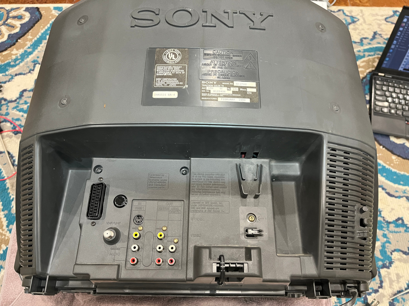
I'm fairly new here, and even though I'm pushing 40 and a EE, I'm pretty new to the inner workings of CRT TVs. That being said, I picked up a Trinitron KV-27V40 a few months ago and last night I wrapped up its rgb mod referencing a conversion done by @tysonwarrior2 here:
viewtopic.php?p=1355747#p1355747

And using Syntax and MarkOZLAD's OSD Mux RGB Mod Circuit v2 excel sheet / value calculator.

The result is a 95% perfect with amazing color and working sound. However, I'm getting the apparently common issue of a shifted image (to the left) when using the RGB mux.
I apologize if this is a daily question here. I can honestly say I spent several hours reading here trying to nail down a solution before posting.

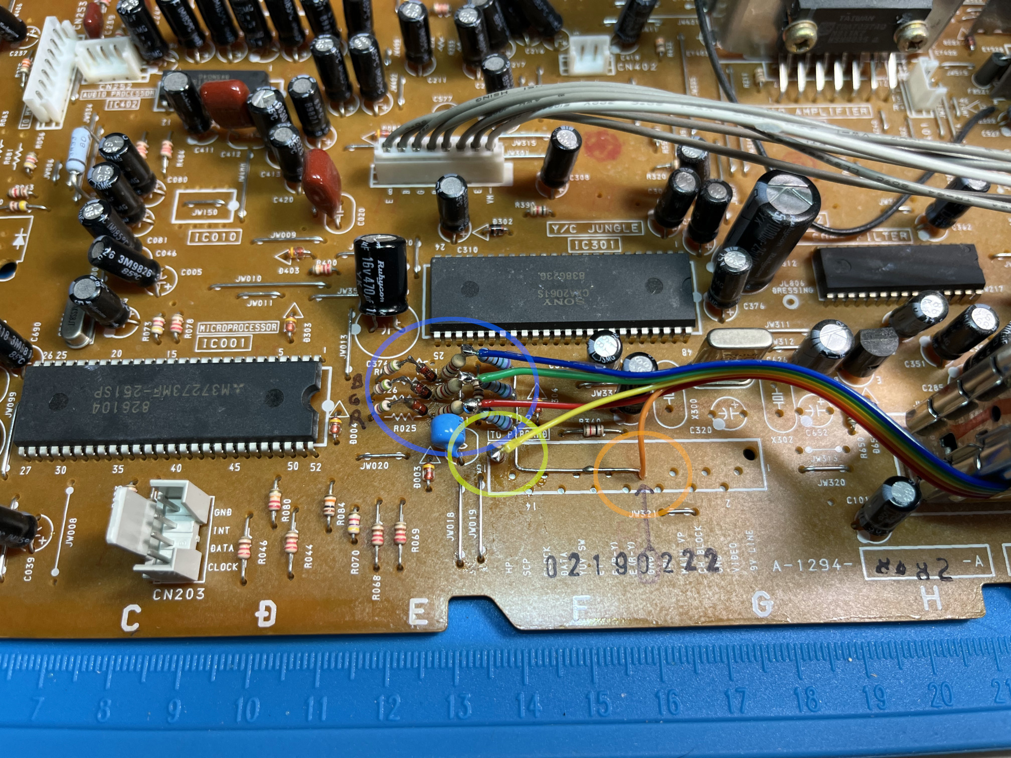
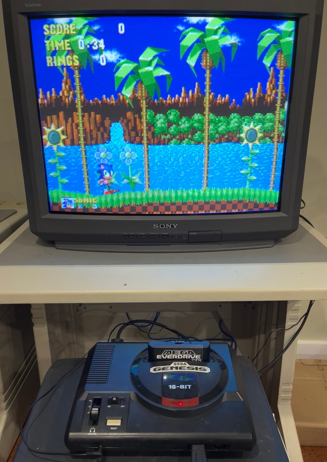
Here's where things things started:

Image
Image
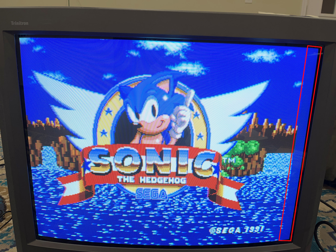
*Note - The emphasis of the red box was added in post

This is being sent to the TV via a NTSC SMS 1 + a Csync SCART cable from retro-access:
https://retro-access.com/collections/vi ... nc-tv-lead

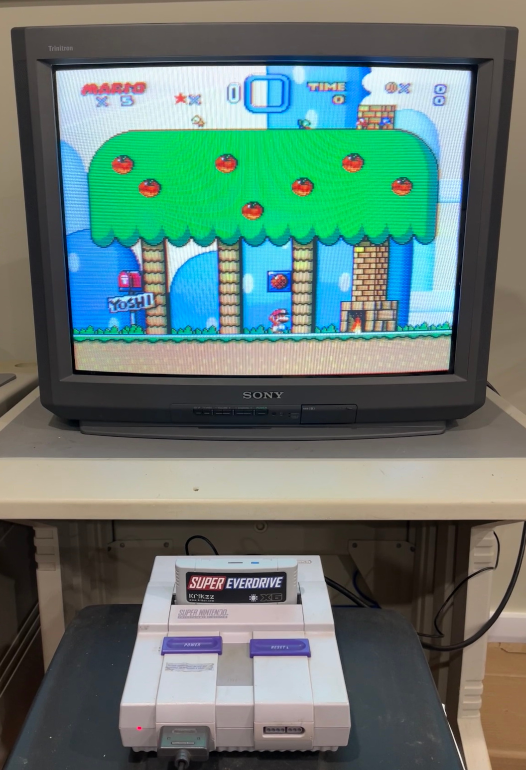
*Note this also happens out of my NTSC SNES using a Csync SCART cable from retro-access.

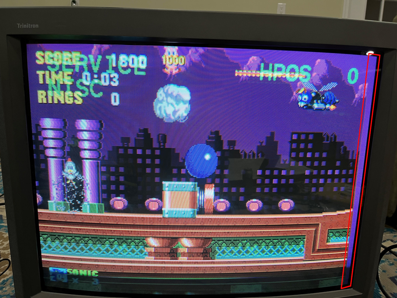
Here's the best improvement I've been able to do via the service menu + HPOS, but at this point, I've run out of adjustment:

Image

As I mentioned before, I referenced @tysonwarrior2 's work on an identical set. He mentions something in the thread above about a resolution to the image shit. Specifically:

"As for sync You CAN put it in through the composite port, but I suggest using the S-Video port, since it bypasses the comb filter IC, which fixes the issue with the image shifting offscreen to the left."

This is what I don't understand and would love some clarification on. I would message tysonwarrior2, but he's long since been absent and it appears PM privileges haven't been granted due to my noob status maybe.
For those of you who are more knowledgeable... Can you shed some light on this? Is it possible to feed the Csync signal into the Svideo port like to its Luma pin? If so, would the cable's Csync resistor need to be changed / removed?

Any other ideas outside of a scart centering circuit?

Any help is greatly appreciated
Lane
MarkOZLAD
Posts: 1025
Joined: Thu May 18, 2017 12:39 pm

Re: Please save me from a centering circuit - RGB Trinitron

Post by MarkOZLAD »

halfspec wrote:Can you shed some light on this? Is it possible to feed the Csync signal into the Svideo port like to its Luma pin? If so, would the cable's Csync resistor need to be changed / removed?
Leave resistor in place and feed csync into S-Video luma. You will also need to trigger the S-Video "sense". You could do this by cutting an s-video cable head and putting it into the s-video port, or you could modify the circuit.
___________________________________________________
MarkOZLAD
OSD/External RGB Mux Diagram
OSD/External RGB Mux Resistor Value Table 0.7Vp-p : 0.5Vp-p

"Imagine toggle switch OSD modding a TV in 2019" - maxtherabbit
halfspec
Posts: 9
Joined: Wed Dec 08, 2021 3:26 pm

Re: Please save me from a centering circuit - RGB Trinitron

Post by halfspec »

MarkOZLAD wrote:
halfspec wrote:Can you shed some light on this? Is it possible to feed the Csync signal into the Svideo port like to its Luma pin? If so, would the cable's Csync resistor need to be changed / removed?
Leave resistor in place and feed csync into S-Video luma. You will also need to trigger the S-Video "sense". You could do this by cutting an s-video cable head and putting it into the s-video port, or you could modify the circuit.
Thank you very much Mark. That did in fact work.
I tried posting this 2 days ago, but it took a while to get approved by the admins.
Between then and now I spent a couple more hours in the mega RGB TV mod thread and found several posts about people using the s-video luma input for c-sync. That bolstered my confidence enough to try 2 nights ago.
As for the s-video sense issue. I had to figure that out on my feet after just wiring c-sync to the svideo luma produced an un-synced video signal. I finally realized that the schematics showed a NO contact in the svideo diagram and I figured it was a plug in sensor. I confirmed / verified, then hardwired it closed to perform my test which worked perfectly!

I've since been watching for this post to get approval so I could save folks from wasting their time helping me out. Hopefully I didn't burn much of your time.

Thank you again for the help.
Lane

PS - I've since removed the hardwired short for the s-video sense circuit and made a pair of dummy plugs for s-video and the right channel rca so I can still plug in composite video sources and mono audio sources.
User avatar
matt
Posts: 614
Joined: Mon May 09, 2005 5:46 am
Location: Honolulu, Hawaii

Re: Please save me from a centering circuit - RGB Trinitron

Post by matt »

You can wire up the S video sense pin in tandem with blanking if you use a DPDT switch. Then it will automatically switch to Svideo when you enable RGB but you'll still be able to use A/V cables.

It's also possible to add a second A/V input on these TVs, although for most people it's not worth the trouble.
ElBartoME
Posts: 82
Joined: Tue Aug 07, 2018 5:55 pm
Location: Germany

Re: Please save me from a centering circuit - RGB Trinitron

Post by ElBartoME »

Just as additional information: Most Sonys have, in addition to the H-POS in the service menu, a switch with three positions on the deflection PCB. With that you can position the screen left, center or right.

Here it is in the 27V40 on the A-Board (SWS01):

Image
halfspec
Posts: 9
Joined: Wed Dec 08, 2021 3:26 pm

Re: Please save me from a centering circuit - RGB Trinitron

Post by halfspec »

ElBartoME wrote:Just as additional information: Most Sonys have, in addition to the H-POS in the service menu, a switch with three positions on the deflection PCB. With that you can position the screen left, center or right.

Here it is in the 27V40 on the A-Board (SWS01):
Ah hah! I've seen references to these switches in other posts, but even with a couple of pours over the service manual I never found reference to it on my set. However, after seeing your schematic, I easily picked it out on mine. Excellent information if one wanted to stick to using the composite video input as the destination for Csync. As it is, bypassing the comb filtering on the composite video input and going the more direct path via the s-video luma input, my sync signal arrives in much better shape and I'm back to factory HPOS settings.

matt wrote:You can wire up the S video sense pin in tandem with blanking if you use a DPDT switch. Then it will automatically switch to Svideo when you enable RGB but you'll still be able to use A/V cables.

It's also possible to add a second A/V input on these TVs, although for most people it's not worth the trouble.
Thank you for the great information Matt. I only ended up with a SPDT switch to handle my blanking override for this project which I'm very happy with and after removing the cover off of this TV ~10x times I believe I'm ready to stick a pin in this one :D

The results have far exceeded my expectations and because this set will spend 99% of its time on its SCART input, I'm perfectly happy using the pair of dummy plugs.


Thank you all again!
Lane
halfspec
Posts: 9
Joined: Wed Dec 08, 2021 3:26 pm

Re: Please save me from a centering circuit - RGB Trinitron

Post by halfspec »

For anyone else attempting this mod on a KV-27V40 and want some specifics to compare against, here are my notes / results:


Image
Image
Image
Image


All of the resistors in the pics / schematic were generated using MarkOZLAD & Syntax's OSD Mux RGB Mod Circuit v2 excel sheet / value calculator
The blanking circuit was based off of work done by tysonwarrior2
*Note - If using the S-video Luma input for your sync signal, you must activate the s-video plug which means it's plug sensing contact must close. This can be done by hardwire / shorting the switch, wiring it up to an external switch, or plugging in a dummy plug / full blown s-video cable. The same note applies to the Right audio channel plug. If you don't address the plug sensing contact, you'll only feed mono / Left channel audio in and it will be played through both speakers.

The colored circles correlate to areas of interest on my updated schematic which I will link below due to it being uploaded in high resolution:

KV-27V40 RGB SCART Schematic

Parts:

Resistors used in my application were 5.6kΩ, 1kΩ, and 75Ω.
The diodes used for my application are both 1N4148 diodes.
SCART Connector
Switch
Ribbon

More Pics + Results:

Image
Image
Image
Image

I appreciate everyone's help and hope this thread can help someone avoid the pitfalls I stumbled in :mrgreen:

Lane
User avatar
matt
Posts: 614
Joined: Mon May 09, 2005 5:46 am
Location: Honolulu, Hawaii

Re: Please save me from a centering circuit - RGB Trinitron

Post by matt »

halfspec wrote:Ah hah! I've seen references to these switches in other posts, but even with a couple of pours over the service manual I never found reference to it on my set. However, after seeing your schematic, I easily picked it out on mine. Excellent information if one wanted to stick to using the composite video input as the destination for Csync. As it is, bypassing the comb filtering on the composite video input and going the more direct path via the s-video luma input, my sync signal arrives in much better shape and I'm back to factory HPOS settings.
Even using the horizontal position switch, the picture is still shifted too far to correct if you're using the composite input. You can mostly center the picture but the left side blanking is off. You really do have to use the Svideo port to get it to work right.

However, another useful feature of this switch is that you can wire it up to another pole of your blanking switch (which by this point has ballooned to 4PDT) which will keep the picture centered when switching back and forth from RGB.
Post Reply