I have a PC Engine (white) and external RGB board with a Mega Drive 2 din that passes CSYNC straight through. It uses a 7314 chip and to my eye through an OSSC, looks great for my needs. I don't want to debate if a 7314 is a poor solution, I'm just interested in using what I have, knowing that I'm not frying my OSSC with CSYNC straight from the expansion port on the back of the console.
After researching what was needed on the CSYNC line (in case it is high voltage TTL level) I saw very mixed opinions, some saying nothing is needed on the line, some saying just a cap, some saying cap+resistor, some saying you need to amplify it, and some saying don't even touch it. I don't have an oscilloscope (or the skills to use one) so was hoping to find something concrete. To perform a quick test, I played it safe and went with a 220uf cap followed by a 470ohm resister on the sync line, and got no sync. So I took off the resistor and got sync, with a much cleaner image (eg no checker-boarding).
I don't want to run with CSYNC for long until I'm sure this setup is fine, and I'm not doing any potential harm to my OSSC. So if taking CSYNC from the expansion port, thinking purely on sending safe levels to the OSSC, what components are needed on the sync line? And in which order?
Thanks
PC Engine CSYNC
-
Kez

- Posts: 840
- Joined: Thu Jul 20, 2017 7:09 am
Re: PC Engine CSYNC
I don't the exact electrical details of this, maybe someone else can chime in, but my understanding is that the CSYNC from the expansion pins is not really suitable for use in this manner as it is wired directly to the chip. I don't think it will damage your OSSC necessarily, but may cause additional strain on the PC Engine Hu6260 or even fry the chip if you get a bent pin or a short in your cable. It's also just not on spec so you might have weird compatibility issues and dropouts.
Anyway, you're supposed to buffer the csync (which is why 4 channel amps like THS7374 are preferred). In the past I built a little buffering circuit with a few cheap components and had good results.. but I can't seem to find the info anymore! If I do I'll post it here.
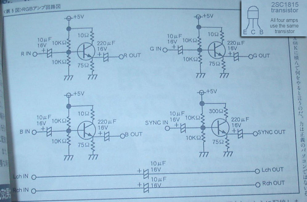
EDIT: Pretty sure it was the sync circuit from the bottom right of this image.
Anyway, you're supposed to buffer the csync (which is why 4 channel amps like THS7374 are preferred). In the past I built a little buffering circuit with a few cheap components and had good results.. but I can't seem to find the info anymore! If I do I'll post it here.
EDIT: Pretty sure it was the sync circuit from the bottom right of this image.
-
jsteel
- Posts: 49
- Joined: Mon Jan 27, 2020 5:19 pm
Re: PC Engine CSYNC
OK thanks that's very helpful. With that circuit, do you just use a straight wire in the cable?
I was hoping this advice was true, that just a capacitor is all that is needed to tame the signal https://pcengine.proboards.com/thread/8 ... using-days
But the circuit you provided here, if that is technically superior, I'm happy to give that a go. I cannot say I understand what it is doing in the slightest but it's within my means to wire up a small board like this and try it out, many thanks.
Also, I wonder if this also applies to the Mega Drive, where I followed advice to take CSYNC from from a chip and attach a capacitor followed by a resistor. Would that also benefit from a similar circuit or are they very different beasts?
-
Kez
- Posts: 840
- Joined: Thu Jul 20, 2017 7:09 am
Re: PC Engine CSYNC
Yeah you would use a straight wire.
I should say - I am not super confident about this!
I just remember vague details from the last time I looked into this several years ago.. I strongly recommend considering looking into some of the PCBs available now for specifically for this purpose, as people have been refining these mods for a very long time now and they don't cost much.
-
jsteel
- Posts: 49
- Joined: Mon Jan 27, 2020 5:19 pm
Re: PC Engine CSYNC
OK thanks I'll wait for further comment then. The reason for wanting to use this setup, is that I want to keep the console unmodified, so taking RGB from the back is my preference. I'm also on a tight budget so don't want to invest in another "back" RGB solution. I can use sync from the composite video for now but would be nice to use CSYNC (just to remove some checker-boarding) once confident that it's not putting stress on the console or OSSC.
And it would be interesting to confirm if I should be equally concerned about the Mega Drive (also taking CSYNC from the chip).
And it would be interesting to confirm if I should be equally concerned about the Mega Drive (also taking CSYNC from the chip).
-
Kez
- Posts: 840
- Joined: Thu Jul 20, 2017 7:09 am
Re: PC Engine CSYNC
It is worth considering the jailbar fix on your console if you haven't already, as that can fix some artefacting that RGB mods can't get rid of.
As for the Mega Drive, it's fine as long as you have the resistor. That signal is on an AV port and designed to be hooked up to an AV cable, whereas the expansion port on the PCE just exposes a bunch of signals from inside the console for use by various devices.
As for the Mega Drive, it's fine as long as you have the resistor. That signal is on an AV port and designed to be hooked up to an AV cable, whereas the expansion port on the PCE just exposes a bunch of signals from inside the console for use by various devices.
-
jsteel
- Posts: 49
- Joined: Mon Jan 27, 2020 5:19 pm
Re: PC Engine CSYNC
OK thanks for clarifying about the MD vs PCE, that makes sense.
I was aware of the jailbar fix but actually I haven't noticed any issues with mine. I'll need to find where they are noticeable and then I'd be happy to swap out the caps to see if it makes a difference.
So I'll leave the question open as to whether the circuit you provided here is the cheapest solution to use the PCE's CSYNC signal without putting any stress on the console or OSSC.
-
kitty666cats

- Posts: 1359
- Joined: Tue Nov 05, 2019 2:03 am
- Location: Massachusetts, USA
Re: PC Engine CSYNC
http://retrotekshop.com/products?pn=TG16AVAMP

^ I’ve never seen anyone who has used one of these things; have always thought it looked interesting. Anyone here have one or know someone who does?
^ I’ve never seen anyone who has used one of these things; have always thought it looked interesting. Anyone here have one or know someone who does?
-
Kez
- Posts: 840
- Joined: Thu Jul 20, 2017 7:09 am
Re: PC Engine CSYNC
Tim Worthington's original page on the fix has a screenshot with an example. It definitely varies in intensity between systems so if you're not experiencing it, it may not be worth doing.jsteel wrote:I'll need to find where they are noticeable and then I'd be happy to swap out the caps to see if it makes a difference.
-
thebigcheese
- Posts: 707
- Joined: Sun Aug 21, 2016 5:18 pm
Re: PC Engine CSYNC
I'm not the one to provide actual schematics to anything, but I see on Voultar's product page for his kit, he says that he takes the c-sync from the 6260 and buffers it through the 7374. It also seems to run through a similar (or the same) set of resistors/caps to the RGB channels. All of this is to say that I think you are right that you don't want to run it straight off the 6260 (or the extension port by extension), but what exactly you'd want to do to it, I don't know.
-
jsteel
- Posts: 49
- Joined: Mon Jan 27, 2020 5:19 pm
Re: PC Engine CSYNC
After a bit more research, I'm thinking I will try building a sync stripper using an LM1881, if that gives me as clear video as the raw csync then that's probably the safest and cheapest solution (with my existing hardware).
-
jsteel
- Posts: 49
- Joined: Mon Jan 27, 2020 5:19 pm
Re: PC Engine CSYNC
I found this https://gamesx.com/rgbadd/duorgb.php (linked from https://www.retrorgb.com/tg16.html) that shows the same image you shared and says
There are also a number of diagrams here suggesting to pass through csync as-is, if using a board that doesn't support csync https://www.otakus-store.net/en/content ... -Duo-Duo-r
Maybe this is bad advice, but many sources seem to suggest using the signal as-is, and I'm struggling to find evidence (actual data) to show that this is bad. I'll still wire up a csync circuit, or sync stripper until I'm confident, and in the meantime maybe someone could share data showing why using the raw csync is bad for hardware health (if it is).
So I don't think there's any harm in trying this but I do wonder how necessary it is.For most monitors it's not necessary, though as mentioned above some won't sync without it
There are also a number of diagrams here suggesting to pass through csync as-is, if using a board that doesn't support csync https://www.otakus-store.net/en/content ... -Duo-Duo-r
Maybe this is bad advice, but many sources seem to suggest using the signal as-is, and I'm struggling to find evidence (actual data) to show that this is bad. I'll still wire up a csync circuit, or sync stripper until I'm confident, and in the meantime maybe someone could share data showing why using the raw csync is bad for hardware health (if it is).
-
Fudoh

- Posts: 13044
- Joined: Mon Mar 06, 2006 3:29 am
- Location: Germany
- Contact:
Re: PC Engine CSYNC
If you're going to use your PC on a CRT, then any kind of sync will do the trick. Hardly anything you can do wrong. But on digital displays using an upscaler of any sort, PCE Sync is really tricky and can cause all kinds of problems. The most solid way to get a proper signal which will work fine on a FM, OSSC or 5X is to boost and buffer the CSYNC signal just like the RGB signals - exactly the way Voultar did it.
-
jsteel
- Posts: 49
- Joined: Mon Jan 27, 2020 5:19 pm
Re: PC Engine CSYNC
Do you mean compatibility problems? During my testing I've had no issues with my OSSC. That's not to say there is no problem here, I'm asking if there is any risk to damaging the hardware, with data to back up the claim. My gut feeling is there's too much difference of opinion to take someones word on this. I'm hoping for something concrete. Thanks
-
Syntax

- Posts: 1827
- Joined: Wed Aug 09, 2017 12:10 am
- Location: Australia
Re: PC Engine CSYNC
PCE Csync is taken directly from the Hu chip, un buffered.
This means 0 protection from outside sources sinking too much current and overloading it OR a hotplug/spike in voltage from an external source which can result in the Hu chip being damaged.
Putting a buffer in the circuit protects the PCE and beefs up sync to an acceptable level. All you will break is the buffer if you did something silly like feed 5v into the sync line, the Hu would be protected.
I personally prefer buffering sync and RGB all from the same stage to avoid slight screen shift. Voultars board is perfect for this.
-
jsteel
- Posts: 49
- Joined: Mon Jan 27, 2020 5:19 pm
Re: PC Engine CSYNC
One suggestion (link above Feb 01, 8:25) was to put a 220uf capacitor on the line and possibly a resistor to drop the voltage a little, (noob question) would that offer any protection? I mentioned before that my Mega Drive takes CSYNC from a chip through a capacitor and resistor, so is that just as much at risk to accidents?
Do you think the OSSC may draw too much? Is this speculation, is this reported to happen somewhere or is it possible to provide some data to back this up?
Thanks
Do you think the OSSC may draw too much? Is this speculation, is this reported to happen somewhere or is it possible to provide some data to back this up?
Thanks
-
NewSchoolBoxer

- Posts: 369
- Joined: Fri Jun 21, 2019 2:53 pm
- Location: Atlanta, GA
Re: PC Engine CSYNC
There is more than one way to define electrical isolation and protection. I think a small resistor is a good idea to protect against open circuit or current spike. I keep TTL level csync where anything between 3.5 to 5V csync would work and 3V wouldn't surprise me. If you're going 75 ohm / ~300 mV level then you'll have a resistor anyway. (Don't send TTL to upscaler unless you know it can handle it)jsteel wrote:One suggestion (link above Feb 01, 8:25) was to put a 220uf capacitor on the line and possibly a resistor to drop the voltage a little, (noob question) would that offer any protection? I mentioned before that my Mega Drive takes CSYNC from a chip through a capacitor and resistor, so is that just as much at risk to accidents?
Do you think the OSSC may draw too much? Is this speculation, is this reported to happen somewhere or is it possible to provide some data to back this up?
Thanks
You can't put a large capacitor in series and expect the circuit to work the same. Either it's needed on the video and/or sync lines or it isn't. The capacitor will block DC, however, a voltage spike will still pass through as a capacitor cannot change voltage instantaneously. This transient is enough to fry a circuit. That's why I don't refer to a series capacitor as protection but it AC couples and you often want that.
What helped me understand analog video capacitors is the short 8 page datasheet (by datasheet standards) for AND8457-D that further explains signal amplitude correction and by extension why we could have a PS1+PS2 RGB cable without a 1000 uF capacitor.
Kez bringing up buffering for connecting different input and output impedances and providing electrical isolation, I'm really impressed. I don't know why I don't see the topic come up more often but as long as we're putting THS7374 on everything then we got the buffering covered. I mean to test other video amps and prove if there's a better replacement or not.
-
jsteel
- Posts: 49
- Joined: Mon Jan 27, 2020 5:19 pm
Re: PC Engine CSYNC
So I built a sync stripper, and using that (from composite video) it looks as clean as csync (gets rid of checker-boarding). However the second game I tested (after playing another for 10 minutes or so), sync drops every so often via my OSSC (can be some seconds or a few minutes). Using the PCE csync it never drops, so I'm not sure what is going on there and why it may be game-specific.
I was interested to see the peak-to-peak voltage between the sync stripper and csync so I bought a cheap oscilloscope and under load the sync stripper reads about 300mV and csync reads about 220mV. From my understanding these are quite low levels for csync but doesn't explain why the sync stripper drops if the level is more reasonable.
There was talk of amplifying the csync signal here and maybe that is the right thing to do, to basically double it. But if my OSSC is happy with it then I'm left wondering if it is really going to put strain on the console as speculated here. I understand you can put strain on a chip if you for example split it between two TVs, and therefore twice is being drawn. But one TV reading the sync signal ~80mV less than what a sync stripper provides? I'm still not convinced that it shouldn't be used as-is.
-
Syntax
- Posts: 1827
- Joined: Wed Aug 09, 2017 12:10 am
- Location: Australia
Re: PC Engine CSYNC
If you built a stripper with one of the popular IC like an LM1881 or EL1881 you don't need an amp as they are one, they output 5v TTL level sync if powered by 5v.
EL1881 can be powered by 7v and will output 7v TTL, LM1881 can take 12v and will output 12v sync
So if using one of those, power it with 5v then just put a 470R resistor inline to bring sync down to a level the OSSC can handle.
That should give you 0.688 vpp.
EL1881 can be powered by 7v and will output 7v TTL, LM1881 can take 12v and will output 12v sync
So if using one of those, power it with 5v then just put a 470R resistor inline to bring sync down to a level the OSSC can handle.
That should give you 0.688 vpp.
-
jsteel
- Posts: 49
- Joined: Mon Jan 27, 2020 5:19 pm
Re: PC Engine CSYNC
Yes it was a LM1881 (I mentioned previously) and I have 470ohm on the sync line. This gives me ~300mV csync. In case my oscilloscope is giving bad readings so I've quickly tested some other consoles for some benchmarks:
Super Famicom with straight-wire (knowing this should be a bit too high) ~690mV. With 470ohm I get more like 300mV.
TW NESRGB ~190mV. J8 closed, maybe I'll open it seeing how low this is, but it has run fine for me for years.
TW N64 RGB ~300mV.
To make it clear I'm not concerned with compatibility, just what could be damaging to my hardware. Maybe someone can read one of theirs to confirm I'm getting sensible results. At least the expected Super Famicom higher reading was there. I'm just not sure exactly what it should be but that's lower than I imagined.
-
Syntax
- Posts: 1827
- Joined: Wed Aug 09, 2017 12:10 am
- Location: Australia
Re: PC Engine CSYNC
It kind of sounds like you are reading the scopes Vavg instead of the Vpp.
Really a cheap multimeter in DC mode will give you the loaded value of RGB( white screen) and sync 90% of the time, as long as the sync polarity is negative you can use the multimeter.
Positive sync with a multimeter in DC will show low mv like you experienced.
Really a cheap multimeter in DC mode will give you the loaded value of RGB( white screen) and sync 90% of the time, as long as the sync polarity is negative you can use the multimeter.
Positive sync with a multimeter in DC will show low mv like you experienced.
-
jsteel
- Posts: 49
- Joined: Mon Jan 27, 2020 5:19 pm
Re: PC Engine CSYNC
It's Vpp. I thought you specifically need to use as oscilloscope as it doesn't matter so much about the voltage reading but the peak to peak, which you cannot get from a multimeter. But maybe this is going to get off topic; I'm not really interested in using a multimeter for something an oscilloscope is more suited for. If someone shares values from their consoles and it's showing my oscilloscope is way off, I'll just end up buying a better one!
However what my readings are showing, is that the PC Engine csync is between the values of my NES and N64 RGB boards (both Tim Worthington) which gives me confidence that whatever the reading truly is, it is within a common range.
However what my readings are showing, is that the PC Engine csync is between the values of my NES and N64 RGB boards (both Tim Worthington) which gives me confidence that whatever the reading truly is, it is within a common range.
-
Syntax
- Posts: 1827
- Joined: Wed Aug 09, 2017 12:10 am
- Location: Australia
Re: PC Engine CSYNC
For what you are doing one is not needed, the values of raw csync and comp video are documented and the chip you are using just straight up amps any signal from .5 /2vpp to TTL 5v.
300mv is the lowest OSSC will take im pretty sure, you can safely lower the resistor value to 330R and test that regardless of your scopes readings.
It should give you close to 1vpp, anything can take that.
Safe depends on the chip accepting sync.
Old chips like a CRT run 5v, and so can handle up to that before they pop.
New chips are 3.3v. so really the OSSC should be able to take close to 3vpp sync without damage.
-
jsteel
- Posts: 49
- Joined: Mon Jan 27, 2020 5:19 pm
Re: PC Engine CSYNC
I don't have 330 to hand, but 470 ohms on the PCE csync gives me no signal on the OSSC, so I'm sure it's not 5v TTL level. 470 on my N64, I still get a signal (wow this must be really low, and OSSC is still happy). 470 on my NES I get no signal. Again this confirms the readings I'm getting seem sane compared to each other (it can at least tell me which console has a higher or lower Vpp). Maybe you can share your readings if you are doubting mine?
Hmm OSSC can take 3Vpp sync via scart? I'm going to really need some evidence to back up your claims as everything I have read up to today says this is an absolute no.
Examples:
- "sync should be between 250mV and 900mV for SCART", "2.5v = Broken OSSC" https://www.retrorgb.com/osscarcadetimings.html
- https://www.junkerhq.net/xrgb/index.php ... B-SCART.29
-
jsteel
- Posts: 49
- Joined: Mon Jan 27, 2020 5:19 pm
Re: PC Engine CSYNC
I just realised that I wasn't capturing the occasional sync for the... vertical alignment reset? The one that drops occasionally. Including that, my PC Engine csync shows ~430mV peak to peak. My NES RGB shows ~300mV. Aside from these more reasonable values, I notice that the NES RGB has a Vmax of 0.3V and Vmin 0V. Whereas my PCE has a Vmax of 1.65V, with Vmin of 1.22V. Does this higher voltage in general mean anything of interest? It's not just csync; if I use the PCE composite video instead, that is showing similar voltages with a peak to peak of ~610mV. I'm just curious if the voltage max/min is anything to be concerned with. Thanks
-
Syntax
- Posts: 1827
- Joined: Wed Aug 09, 2017 12:10 am
- Location: Australia
Re: PC Engine CSYNC
2.5v sync = broken OSSC because it will ring up past 3.3v
Thats why I said "close to 3v" not 3.3v.
Whoever said that gave a little more headroom than I did.
.6v or more voltage spikes are a thing.
Check your input voltage is 5v, feed it composite video or csync I forget which one your using but test the other one.
If connecting to the sync line put a 150r inline to limit current pulled from the video chip.
-
jsteel
- Posts: 49
- Joined: Mon Jan 27, 2020 5:19 pm
Re: PC Engine CSYNC
I believe something even above 1Vpp is not advisable. I mean, the SFC outputs something around this and people say put a 330 to 470ohm resistor on it when using the OSSC as it is too high. I don't know what point you are trying to make but I believe my goal is to output 300 to 700mV of csync, and to find out why people advise against using the PCE csync.
I tested adding a 220uF capacitor to the csync line as someone had recommended (link shared previously) and that gives me ~320mV peak to peak, with a Vmax of 24mV and Vmin of -290mV. To me this seems much more like the NES RGB board readings so I am going to proceed to use this in my setup.
To keep this on topic or to conclude this thread, evidence of why PCE csync should not be used would be very interesting.
-
Syntax
- Posts: 1827
- Joined: Wed Aug 09, 2017 12:10 am
- Location: Australia
Re: PC Engine CSYNC
The FPGA used in the OSSC runs off 3.3v and its GPIO pins can do 3.3v. Look at its data sheet.
Because the Hu was not designed to drive 2 loads on the csync line. Anything else that taps it should be buffered to avoid sinking too much current from the Hu and damaging it.
Because the Hu was not designed to drive 2 loads on the csync line. Anything else that taps it should be buffered to avoid sinking too much current from the Hu and damaging it.
-
jsteel
- Posts: 49
- Joined: Mon Jan 27, 2020 5:19 pm
Re: PC Engine CSYNC
What 2 loads are you referencing? Or do you mean if I were to have it split between the OSSC and another device/TV? I wouldn't do that, so keeping my usage to 1 device/load, there is no concern? Thanks.
-
Syntax
- Posts: 1827
- Joined: Wed Aug 09, 2017 12:10 am
- Location: Australia
Re: PC Engine CSYNC
You make a good point, Id forgotten that the csync output of that chip is not used by anything else in the system.
Still its a direct connection to the chip with no protection against sinking too much current. A buffer is safer. A cap and resistor are a cheap semi effective way to do this.
Id say most plug in devices that use the csync signal would do this.
If you look at Dreamcast VGA the Sega designed cable has a buffer chipas the H V sync signals are tapped from between 2 chips, but cheap ebay cables will just put a 150R resistor on the sync lines to protect them. Real world I dont think i have ever heard of the ebay cables hurting a DC.