Here is a guide how to get proper colors, you'll need an oscilloscope and 240p test suite able console (or a pattern generator).
1.
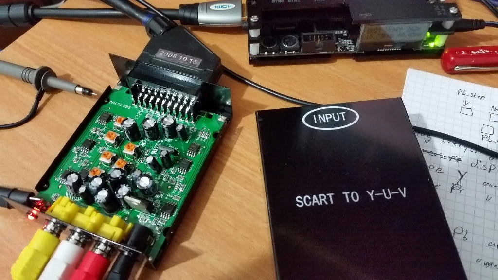
Plug everything and make sure the output of this scart-to-yuv box is terminated to 75ohm (like the OSSC or a TV).
Make sure you use a well balanced console that has equal RGB values when terminated to 75 ohm and can run the 240p test suite.
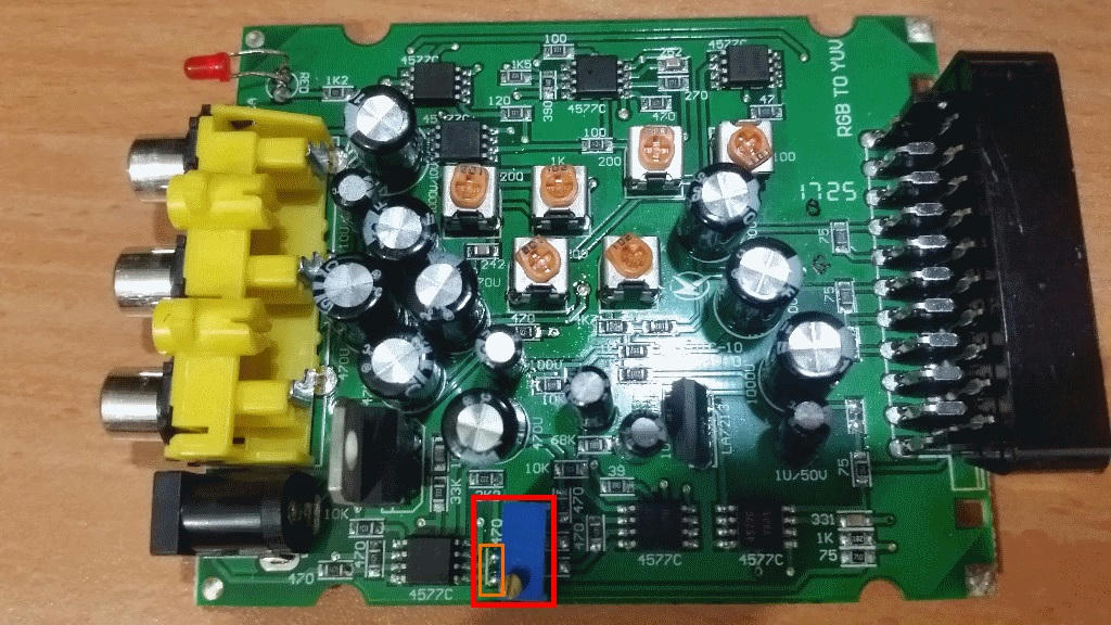
Start will all trimmer pots at middle position, towards the middle leg.
2.
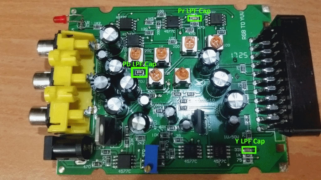
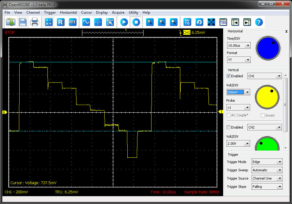
Display SMPTE Color Bars 100% from the 240p test suite and scope the Y (Luma) black to white (no sync) line from the scart-to-yuv box (terminated of course), write down this number.
EDIT: The Y output amplitude is fixed, but adding a trimpot can change that, see fourth post of this thread.
3.
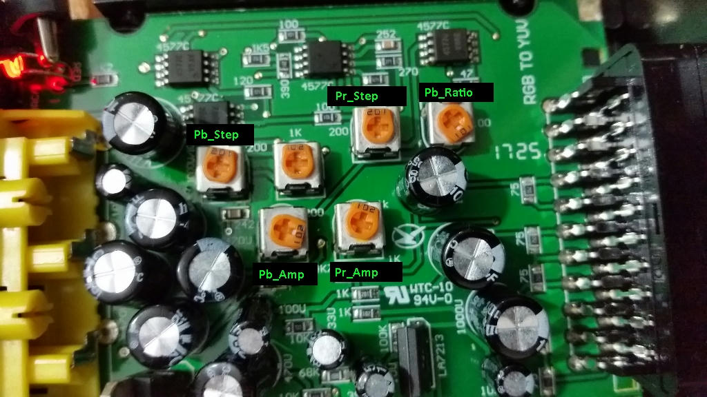
Scope Pr and adjust Pr_Amp till it has the same amplitude peak-to-peak as the Y line.
4.
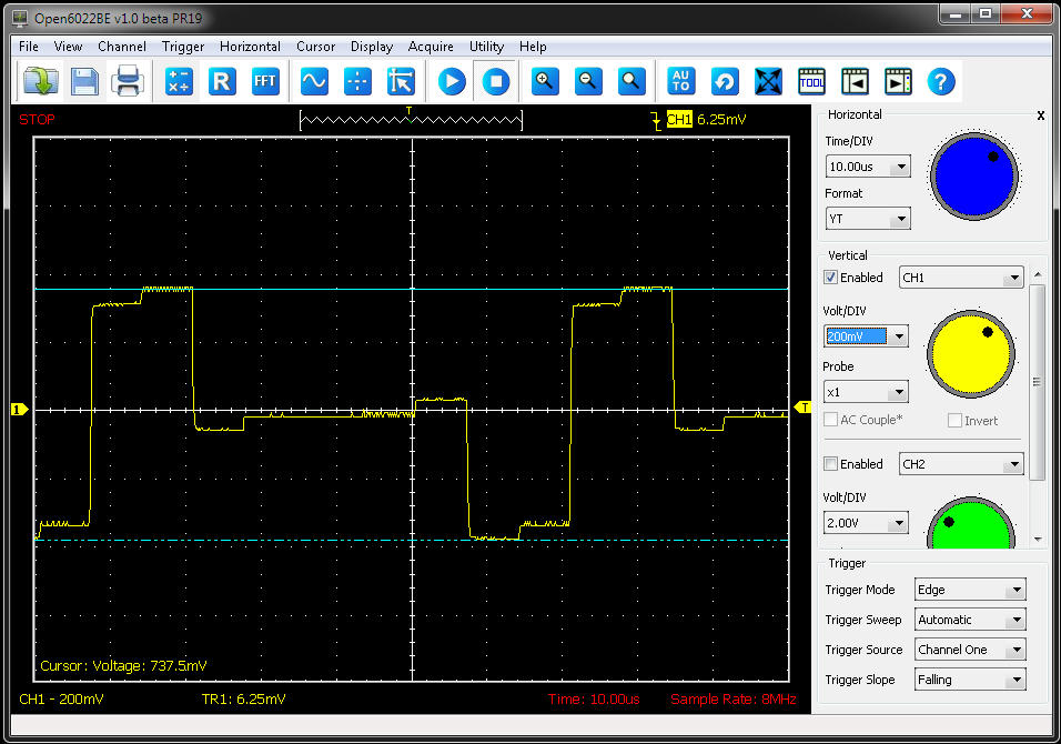
Scope Pb and adjust Pb_Amp till it has same amplitude as Y, this trimmer doesn't have enough range so I set it to Max (fully clockwise).
Now the important color fixing procedures.
5.
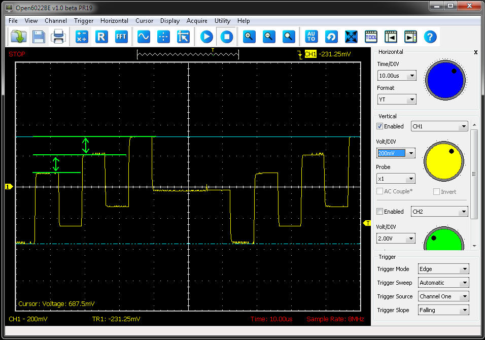
Scope Pr and adjust Pr_Step (Pr Offset) till the is no visible step (see image with marked colors where the step is).
Play with the trimmer first to see the right side of the step go higher and lower than the left side of the step.
You can change the voltage deviation in your scope to a lower value to show the step more clearly resulting in finer adjustment.

6.
Scope Pb and adjust Pb_Step (Pb Offset) till there is no more visible step, exactly the same as you did with Pr in point #5.

7.
Continue to scope Pb and adjust Pb_Ratio till the amplitude difference between the first-to-second and second-to-third peak is equal (see image).
Play with the trimmer first to check how it affects the middle peak.
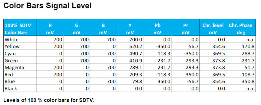
*Note the voltage delta in Pb between Cyan-Magenta-Blue in the chart at the bottom of this post.
Magenta-Cyan = 231.7-118.3 = 113.4
Blue-Magenta = 350-231.7 = 118.3
The result is roughly the same, so just make the voltage delta on both equal.
Now start over and check that everything did not change, fine tune, etc, etc...
Note that the trimmer pots are different in tolerance (around 20% for these Chinese trimmers), so just copying my trimpot positions from the image will not do, might even get things worse.
With proper adjustment I get very close to RGB quality colors and grey balance when the YPbPr signal is decoded with the OSSC, this box is truly useful now.
Here's a useful chart:
Here is a very useful document about Component (YPbPr) video signal:
https://cdn.rohde-schwarz.com/pws/dl_do ... 107_0E.pdf
PS.
Better to use a 7.5v or 9v power supply with this box since the LM7805 inside gets too hot with 12v.
Cheers.