Bratwurst wrote:An oscilloscope would be the best tool here, on the pins of the chip you want to see .7vpp on the composite output and .7vpp or TTL which is 5vpp(??) for c-sync. I don't have a Neo Geo AES at my disposal to check what c-sync should be at exactly.
Possible that a vias for one of the caps cracked at the very start of the trace when you did your capacitor replacement, you could check continuity with a multimeter from each leg of the caps you replaced to the other end of the trace leading from that particular leg.
Is composite output working, have you tested that on another tv?
Firstly, thank you for the help thus far. It is appreciated.
Let me jump to composite... it works just fine. Dunno why I didn't think to try that.
All continuity has been checked. No issues there.
My oscilloscope knowledge is limited (really only used for audio repair). I do have a small one I could test.
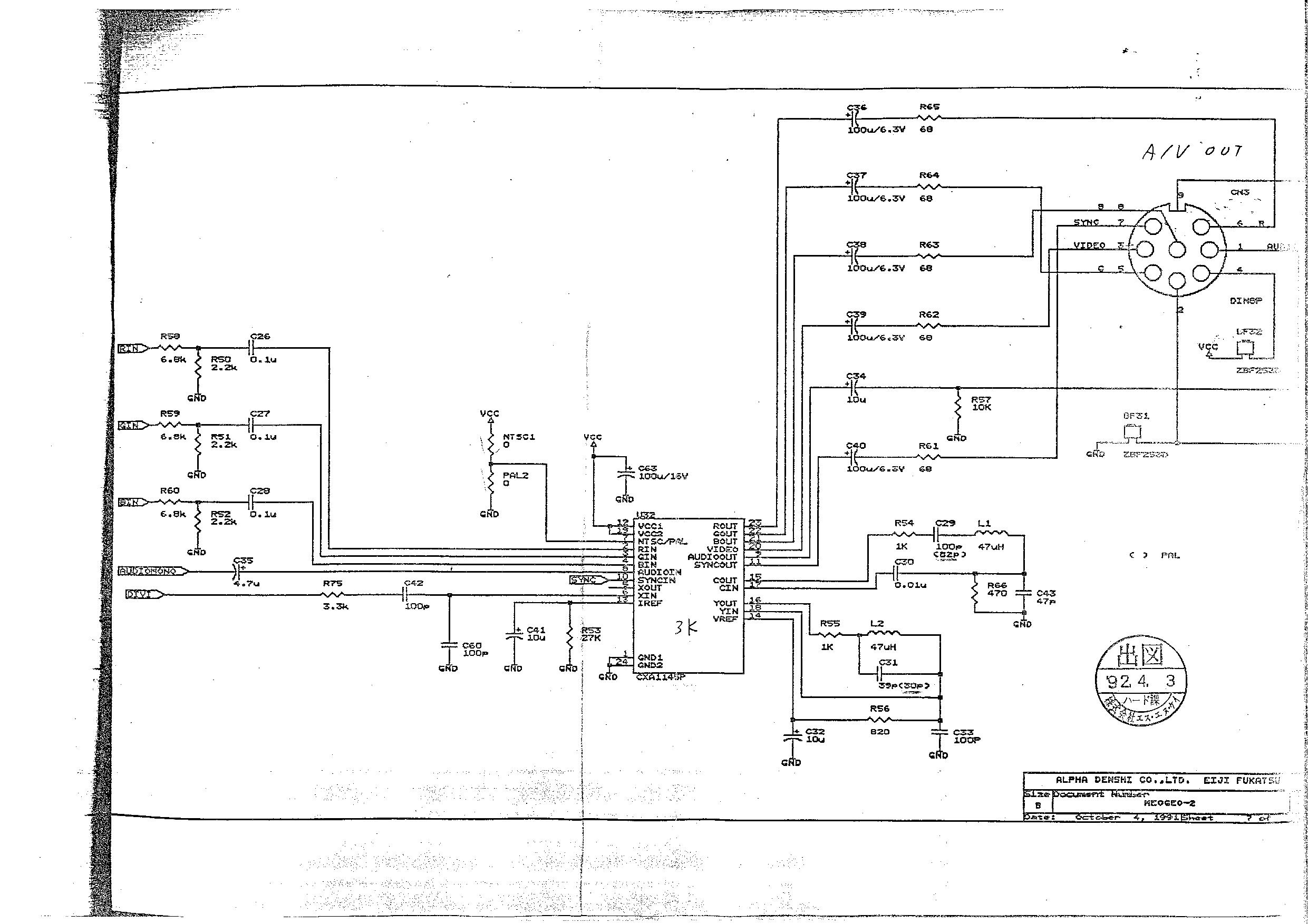
I have been using this schematic to try and troubleshoot.
https://wiki.neogeodev.org/images/c/ca/ ... ge-007.jpg
So I know it is outputing composite video signal fine. My understanding is that the sync in the composite out is the same as RGB + Sync just also mixed in with the video signal.
Now, while I checked continuity from the chip to other components throughout the board. I probably didn't check from the Sync out all the way to pin 7 of the DIN connector.
That's where I am.


