
Sadly I tried this and there's only a small difference. I already had it set to 0; when set to 1, I lose one bar of color in the 240P Test Suite (4 last color bars when set to 0, only the last 3 when set to 1). Thanks a lot anyway! I just ordered an alternative remote for my TV, so I can use all of its functions without messing with service mode.MikeIronFist wrote:Kabal, just wanted to add: I've seen colors in my OSD get weird and blocky like that when I change the "DRGB" setting in the service menu to 1, which presumably enables digital RGB. So it might seem silly to try this, but see if there's a DRGB item in your service menu and see if you can set it to 0. This is total guesswork but since I've seen IC switchable digital RGB once already, I think it might be worth checking before you do any more soldering. If it's not changeable in the service menu then you can still try the other pins (16, 17, 18) as recommended and see what you get.
Alright, I printed the schematics to analize the new pins, and will probably do the new installation next week. I will update with results. I also have to fix a sporadic pincushion problem. Hopefully just a dry solder.Syntax wrote:Kabal2X wrote:Syntax wrote:Kinda looks like you put the wrong voltage to blanking and its going into Half-tone.
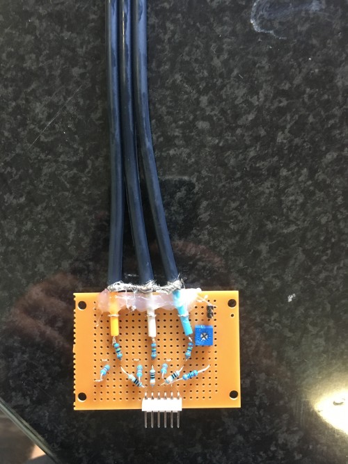
Hmm I'm using 5v to blanking, pin 9 of CXA1313S. The diagram says .1v, does this means its actually expecting 0.1v? Thanks Syntax, I have a feeling this may be the problem. Is there a way to know how much voltage I need to put there?
For blanking you need 5v going through a 180R resistor then a 75R termination to ground before the blanking pin normally.
But from the document you posted it seems you are bypassing the brightness control and clamping of the jungle by not using pins 16 17 18. Could be the issue. Blanking seems to be Ys which is pin 15
Thanks all for your help


