
Why consolize CPS2?
Capcom's CPS2 arcade platform has an awesome library, and the PCBs are housed in plastic shells that makes moving them around like console equipment much less daunting and risky than casually moving around your typical bare arcade PCB. It's also convenient that system board (A) and game boards (B) are detachable with relative ease so you can could just consolize one system 'A' board and then be able to swap all your game 'B' boards with it (if they're all a compatible region).
Power Considerations
Overview: So I assume the gist of powering the A board in a console like fashion would be to get some pico PSU installed internally, wire a power jack and switch to that are mounted to the 'A' board shell, connect 12v and 5v from the picoPSU to the next solder point after the appropriate pins on the JAMMA connector.
Specifics: Here's where things are a bit hazier for me. I'm capable of doing all the steps in the overview, but I don't know what parts are in spec.
1.) I don't know what kind of amps CPS2 needs on 12v and 5v, thus don't know what picoPSU would be sufficient.
2.) After finding a sufficient picoPSU, I don't know how many amps would be needed for a 12v external power brick to power the picoPSU.
3.) Most (all?) arcade PSUs have a way to adjust 5v. A picoPSU does not. How picky is the CPS2 hardware? If the picoPSU is a bit off on its 5v output such as 4.9v or 5.1v, will the CPS2 hardware throw a fit or have other issues? If so, is there a reasonable way to mitigate the potential variance across picoPSUs?
If there's no picoPSU with the appropriate specs for CPS2, what are other internal PSU options?
Audio/Video Output
Overview: Requirements for this section will probably vary by personal preference, so I guess I'll cover most options and divide it into Digital and Analog.
- Digital: This is a must for me so I can easily take this over to friend's houses and such, whom the majority do not own CRTs or fancy upscalers. It looks like marqs' CPS2 digital AV interface will be excellent for getting HDMI output out of the CPS2 viewtopic.php?f=6&t=59479 . I'm basically just waiting on a source for pre-assembled boards to be on sale since there's no way I have the skill to hand solder all those components
- Analog: RGBs can be tapped from/close to the JAMMA connector, then this can be fed to other encoders if you want component/s-video/composite. CPS2 already has RCA jacks for stereo audio, so those can just be used for convenience and to help prevent crosstalk between analog video signals and audio.
Specifics:
- Digital: Might as well keep these specifics to marqs' thread linked above since there's far more info there than I could summarize here and it's still ongoing.
- Analog: Even though RGBs is output on the JAMMA connector itself, I'm not sure what components/circuits are required to get it within spec for standard analog video hardware (aka, not arcade monitors). I also don't know what the best modern video circuit/encoder options are for getting component (YUV)/s-video/composite from RGBs in a nice solution that can be installed internally. I'd also be curious as to what everyone's suggestions would be on what connector to use to carry all the analog video signals on one connector to keep things sleek without drilling holes for tons of various analog video ports (though I imagine a switch might be needed to switch between RGBs and YUV). A connector that can reasonably sourced and doesn't have to be harvested off of old consoles and such would be preferred. Bonus points if it's a port that could be made compatible with existing console cables.
Controllers
Overview: I imagine opinions on how to handle this may vary wildly, but I'll start with my vision and we can go from there. Undamned's consolized CPS2 just has USB ports so you can use your existing 360/PS3 fight sticks and controllers. I assume other USB controllers are probably compatible as well. I'm actually not too keen on this myself and would prefer DB15 ports instead. With DB15 ports you can use Neo Geo controllers/sticks, many other supergun sticks people have made around DB15, plus various adapters such as Undamned's own DB15 USB decoder.
Specifics:
1.) Mounting ports: Even though I'd HIGHLY prefer DB15 ports, I'm not entirely sure if the 'A' board internals will allow a good place to mount them. I'd also like to know if there's a nice clean recessed option for mountable DB15 ports instead of the typical metal ones that stick out a fair bit kinda kill any sleekness you might be going for.
2.) 3 and 4 player: The 34 pin connector between the JAMMA connector and the stereo RCA jacks has the connections for games that support 3 or 4 players. Now I'm extremely skeptical of being able to fit 2 more DB15 ports on the 'A' board shell in addition to already needing 2 for player 1 and 2. It'd be nice if there's a way to make it work, but if there's not you can always make an adapter. I'd have to look up the part number and such again if anyone needs to know but basically I just bought the connector and pins, then built an adapter where it breaks out into 2 DB15 ports for player 3 and 4. This works fine for controllers that connect directly to DB15, but if you want to use adapters (which will more than likely need 5v) then that complicates things. The pinouts I see for the 34pin connector only have 12v on it, so you'd either need something in your adapter to convert 12v to 5v, or disconnect 12v on the port itself and connect 5v instead (does anything that connects to that port even use 12v?)
3.) Kick Buttons: Kick buttons for fighting games also have their connections on the 34 pin connector. This could "simply" just have the corresponding pins connected to player 1 and 2's DB15 connectors (more details below)
4.) Kick Buttons, Button 4, and Player 3/4 Buttons Living in Harmony?: Here's where things get more complicated If you care about having all the control capabilities.
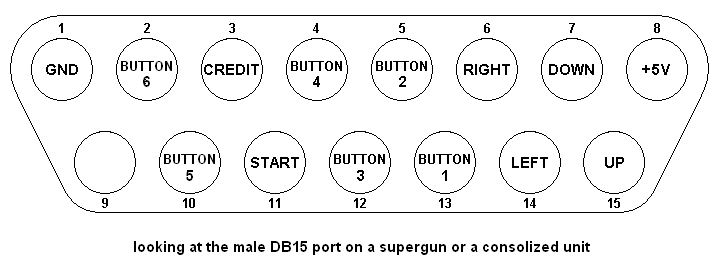
a.) Potential conflict between Button 4 and Kick buttons? Some games, such as the D&D games, use a 4th button which is taken from JAMMA pin 25 (player 1) and pin C (player 2). Now this seems to be the typical pinout for DB15 arcade/superguns http://www.etokki.com/image/data/db15_laugh.PNG. The question is, if pin 4 of the DB15 port is connected both to the JAMMA connector and the 34pin connector for a kick button, is that going to cause issues? No game is going to try to use both JAMMA button 4 and a 34pin connector kick within a singular game, so my main concern is whether or not both being connected to the DB15 port would cause undesired results in the controls or potentially even damage the PCB or controller
b.) Switching between kicks and 3/4 Player: Having the kicks permanently connected for Player 1 and 2 will definitely cause issues when playing 3 and 4 player games. The 34pin connector shares some of the same pins for the kicks and Player 3/4. If player 1 or 2 were hitting buttons 4/5/6 on their controller/stick it would be pressing some of the buttons for player 3 and 4. This is obviously not wanted, so some sort of switch would need to be in place to switch between having kicks connected, and no kicks connected for 3/4 player. Basically a 6 pole single throw (6PST) switch, or a 6 pole double throw (6PDT) switch just used as a 6PST switch. These seem kinda large, so I'm not sure if some simple electronic switching circuit would be better. Let me know your ideas.
c.) A + B (sections above, not CPS2 boards): If 'A' above is actually an issue, then 'B' would need to revised to be a 7PST switch. Switch position 1 would have JAMMA button 4 disconnected and kicks connected. Switch position 2 would have JAMMA button 4 connected and kicks disconnected so no issues are caused with 3/4 player games.
Other Considerations
CPS 'A' board fan: The stock fan is like a jet engine, especially out in the open when it's not tucked away in a cab. Is the fan really required for running it out on an open table or an open entertainment center, or is it only necessary for arcade cabs in arcades without air conditioning
Keeping JAMMA connector?: Just for the sake of preservation, I'd prefer to keep the JAMMA connector intact so the 'A' board could still be put in a cab. However, I'd like some solution for a fitted plastic cover to go over it to protect it and keep little kids and such from potentially touching it while it's powered on. Something similar to those plastic covers on the edge connector of graphics card brand new out of the box would work, or something fancier that custom fits around it to cover up all the blank recessed space around it would be even better. Got any ideas?


