I've attempted to figure this out on my own, but I'm still not sure what I should be doing. Any assistance would be appreciated.mgerety wrote:Need Help with New Mod: Sharp 25r-s100 Chassis SN-010
Service manual: https://elektrotanya.com/sharp_27r-s50_ ... nload.html
I've traced the R, G, B, and Blanking lines from the IC201 (jungle) IX3354CENI
Pin 14 - R
pin 15 - G
pin 16 - B
pin 17 - BLK
to the IC2001 (System COntrol) IX3492CE:
Pin 18 - R
Pin 19 - G
Pin 20 - B
Pin 21 - BLK
Each line passes through a 6.8K 1/8 W resistor (R2024 - R2027, topside, not surface mount) with a cap tied to ground (C2021-2024 which (yay) aren't listed in the components list.).
That's the only thing between htem, and no topside jumpers to tie into (boo).
Where should I tap in, should I remove any of the existing resistors, and what values should I use for the blanking and the feedback. Any help would be appreciated!
EDIT: Note: I want to do the OSD MUX.
TV RGB mod thread
Re: TV RGB mod thread
Re: TV RGB mod thread
Looks very similar to the one pikkon was trying to mod a couple of pages back.mgerety wrote: I've attempted to figure this out on my own, but I'm still not sure what I should be doing. Any assistance would be appreciated.
___________________________________________________
MarkOZLAD
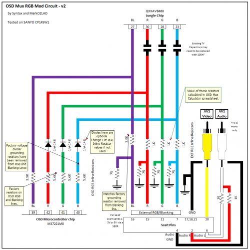
OSD/External RGB Mux Diagram
OSD/External RGB Mux Resistor Value Table 0.7Vp-p : 0.5Vp-p
"Imagine toggle switch OSD modding a TV in 2019" - maxtherabbit
MarkOZLAD
OSD/External RGB Mux Diagram
OSD/External RGB Mux Resistor Value Table 0.7Vp-p : 0.5Vp-p
"Imagine toggle switch OSD modding a TV in 2019" - maxtherabbit
-
burgerkingdiamond

- Posts: 1570
- Joined: Wed Oct 06, 2010 9:56 pm
- Location: Virginia, USA
Re: TV RGB mod thread
I just acquired a Panasonic ct-1110d CRT manufactured in 1983. This set only has rf inputs. Is this possible to RGB mod? My first question would be what to do about the sync..
Let's Ass Kick Together!
1CCs : Donpachi (PCB - 1st loop) Dodonpachi (PCB - 1st loop) Battle Bakraid (PCB) Armed Police Batrider (PCB) Mushihimesama Futari 1.5 (360 - Original) Mushihimesama Futari BL (PCB - Original)
1CCs : Donpachi (PCB - 1st loop) Dodonpachi (PCB - 1st loop) Battle Bakraid (PCB) Armed Police Batrider (PCB) Mushihimesama Futari 1.5 (360 - Original) Mushihimesama Futari BL (PCB - Original)
Re: TV RGB mod thread
Have you got anything that can help us answer the question? A schematic for starters...
___________________________________________________
MarkOZLAD
OSD/External RGB Mux Diagram
OSD/External RGB Mux Resistor Value Table 0.7Vp-p : 0.5Vp-p
"Imagine toggle switch OSD modding a TV in 2019" - maxtherabbit
MarkOZLAD
OSD/External RGB Mux Diagram
OSD/External RGB Mux Resistor Value Table 0.7Vp-p : 0.5Vp-p
"Imagine toggle switch OSD modding a TV in 2019" - maxtherabbit
-
takeshi385
- Posts: 26
- Joined: Sat May 07, 2011 11:10 pm
Re: TV RGB mod thread
Does anyone know how to rgb mod a tv that uses a TA8680N? There is a datasheet for the TA8680N, but it's kind of barebones and in japanese. The tv appears to be permanantly blanking as the screen is always black until a signal such as composite or s video is given to it.
Last edited by takeshi385 on Thu Jan 10, 2019 5:37 am, edited 1 time in total.

Re: TV RGB mod thread
MarkOZLAD wrote:Looks very similar to the one pikkon was trying to mod a couple of pages back.mgerety wrote: I've attempted to figure this out on my own, but I'm still not sure what I should be doing. Any assistance would be appreciated.
It does indeed.
I ending up getting rid of the sharp tv,couldn't get analog rgb to work.
-
retromaniak
- Posts: 45
- Joined: Wed Dec 26, 2018 9:51 am
Re: TV RGB mod thread
Hiburgerkingdiamond wrote:I just acquired a Panasonic ct-1110d CRT manufactured in 1983. This set only has rf inputs. Is this possible to RGB mod? My first question would be what to do about the sync..
https://elektrotanya.com/panasonic_ct-1 ... nload.html
On this page you have a diagram of your TV. There you will find the AN5310 layout. You must connect to the RGB signal output, which you will find on pins 26, 27, 28. Unfortunately, analog electronics is not my strong point, so I will not tell you what capacitors, resistors, etc. You must use, because I just do not have such much knowledge . You are lucky that you do not have any nasty markings on your system because TVs from that period can be surprised by the names of controllers.
-
retromaniak
- Posts: 45
- Joined: Wed Dec 26, 2018 9:51 am
Re: TV RGB mod thread
However, I would like to ask one more thing. In the diagram I presented the SCART connector. However, I would like to ask you which connectors should be used for the RGB signal? I am asking because the SCART connector for the correct RGB signal transmission requires Synchronization, and with this in my case the receiver can be a problem because I have to plug in basically outside Jungle Chip.
Re: TV RGB mod thread
hey guys wanna try a little one of those but the only manual i found is missing schematics its a trinitron 8 inch kv-8ad11
https://www.electronica-pt.com/esquema/ ... b-a-38118/
someone have the complete manual or can send a bit of info on the ics and if it can be modable? planning to get her today

went ahead and buy the thing lol, at least its cute $18 a bit much tho
https://www.electronica-pt.com/esquema/ ... b-a-38118/
someone have the complete manual or can send a bit of info on the ics and if it can be modable? planning to get her today
went ahead and buy the thing lol, at least its cute $18 a bit much tho
Last edited by HellRazor on Thu Jan 10, 2019 5:41 pm, edited 2 times in total.
-
burgerkingdiamond
- Posts: 1570
- Joined: Wed Oct 06, 2010 9:56 pm
- Location: Virginia, USA
Re: TV RGB mod thread
Here is a link to a pdf of the schematicMarkOZLAD wrote:Have you got anything that can help us answer the question? A schematic for starters...
https://elektrotanya.com/panasonic_ct-1 ... nload.html
Let's Ass Kick Together!
1CCs : Donpachi (PCB - 1st loop) Dodonpachi (PCB - 1st loop) Battle Bakraid (PCB) Armed Police Batrider (PCB) Mushihimesama Futari 1.5 (360 - Original) Mushihimesama Futari BL (PCB - Original)
1CCs : Donpachi (PCB - 1st loop) Dodonpachi (PCB - 1st loop) Battle Bakraid (PCB) Armed Police Batrider (PCB) Mushihimesama Futari 1.5 (360 - Original) Mushihimesama Futari BL (PCB - Original)
-
burgerkingdiamond
- Posts: 1570
- Joined: Wed Oct 06, 2010 9:56 pm
- Location: Virginia, USA
Re: TV RGB mod thread
Which color goes to which pin? Do o need to cut the pins and inject the signals to the IC or to the board? What do I do about sync?retromaniak wrote:Hiburgerkingdiamond wrote:I just acquired a Panasonic ct-1110d CRT manufactured in 1983. This set only has rf inputs. Is this possible to RGB mod? My first question would be what to do about the sync..
https://elektrotanya.com/panasonic_ct-1 ... nload.html
On this page you have a diagram of your TV. There you will find the AN5310 layout. You must connect to the RGB signal output, which you will find on pins 26, 27, 28. Unfortunately, analog electronics is not my strong point, so I will not tell you what capacitors, resistors, etc. You must use, because I just do not have such much knowledge . You are lucky that you do not have any nasty markings on your system because TVs from that period can be surprised by the names of controllers.
I'm plenty handy with a soldering iron, but i don't understand the technical details of making this work. Everything I've read makes it sound easy if you just know where to connect your wires too. The fact that this TV is so old that it only has RF inputs adds another piece of uncertainty because I don't know what do about the sync since there's no composite input.
I would like to be able to hook up either arcade boards or any console that supports RGB
Let's Ass Kick Together!
1CCs : Donpachi (PCB - 1st loop) Dodonpachi (PCB - 1st loop) Battle Bakraid (PCB) Armed Police Batrider (PCB) Mushihimesama Futari 1.5 (360 - Original) Mushihimesama Futari BL (PCB - Original)
1CCs : Donpachi (PCB - 1st loop) Dodonpachi (PCB - 1st loop) Battle Bakraid (PCB) Armed Police Batrider (PCB) Mushihimesama Futari 1.5 (360 - Original) Mushihimesama Futari BL (PCB - Original)
-
retromaniak
- Posts: 45
- Joined: Wed Dec 26, 2018 9:51 am
Re: TV RGB mod thread
You do not have to remove the pins. It is enough to solder the wires to them because they are already the output pins which causes that the image will not be processed by the chip (as in most modifications of this type) and it will be sent straight from CRT (the problem is that many portable TVs of that period did not have an RGB input in jungle chip) If you solder cables there, the system will not detect this signal.burgerkingdiamond wrote:Which color goes to which pin? Do o need to cut the pins and inject the signals to the IC or to the board? What do I do about sync?retromaniak wrote:Hiburgerkingdiamond wrote:I just acquired a Panasonic ct-1110d CRT manufactured in 1983. This set only has rf inputs. Is this possible to RGB mod? My first question would be what to do about the sync..
https://elektrotanya.com/panasonic_ct-1 ... nload.html
On this page you have a diagram of your TV. There you will find the AN5310 layout. You must connect to the RGB signal output, which you will find on pins 26, 27, 28. Unfortunately, analog electronics is not my strong point, so I will not tell you what capacitors, resistors, etc. You must use, because I just do not have such much knowledge . You are lucky that you do not have any nasty markings on your system because TVs from that period can be surprised by the names of controllers.
I'm plenty handy with a soldering iron, but i don't understand the technical details of making this work. Everything I've read makes it sound easy if you just know where to connect your wires too. The fact that this TV is so old that it only has RF inputs adds another piece of uncertainty because I don't know what do about the sync since there's no composite input.
I would like to be able to hook up either arcade boards or any console that supports RGB
Below is a link to the specifications of your chip
https://pdf1.alldatasheet.com/datasheet ... N5310.html
-
burgerkingdiamond
- Posts: 1570
- Joined: Wed Oct 06, 2010 9:56 pm
- Location: Virginia, USA
Re: TV RGB mod thread
Thanks! I see where the RGB pins are labelled on the data sheet. Where do I put the sync wire? Sorry if the answer is obvious. Also, do I need to connect to ground to the IC ground or will any ground on the rest of the board work?
Let's Ass Kick Together!
1CCs : Donpachi (PCB - 1st loop) Dodonpachi (PCB - 1st loop) Battle Bakraid (PCB) Armed Police Batrider (PCB) Mushihimesama Futari 1.5 (360 - Original) Mushihimesama Futari BL (PCB - Original)
1CCs : Donpachi (PCB - 1st loop) Dodonpachi (PCB - 1st loop) Battle Bakraid (PCB) Armed Police Batrider (PCB) Mushihimesama Futari 1.5 (360 - Original) Mushihimesama Futari BL (PCB - Original)
-
retromaniak
- Posts: 45
- Joined: Wed Dec 26, 2018 9:51 am
Re: TV RGB mod thread
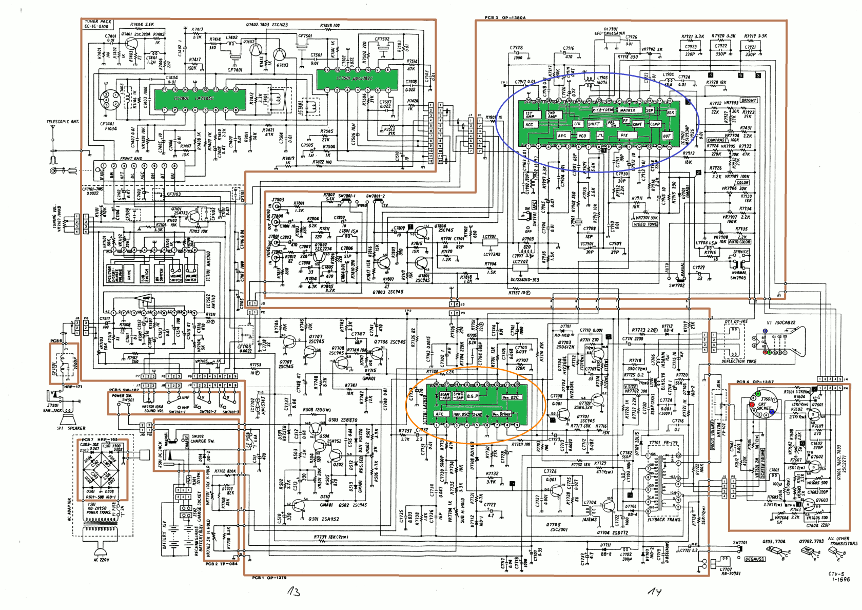
As for synchronization, here the case is quite complicated because, for example, my Orion CTV-5 receiver has a rather unusual synchronization system. namely, he has a separate chip for this task (later televisions have a circuit integrated with Jungle IC). This is where the complications begin, but from the beginning. As I said before, the image generated by the device should be connected in principle outside the image converter, which means that the system has no information on whether the image is sent or not. Therefore, you would have to locate the image synchronization system on your PCB and find the composite sync input there. In my receiver (model mentioned above) which was produced circa 1982, the LA 7820 is this type of work and the composite sync input is on pin 16. You will play the same role with the AN5436 chip and the sync will be on pin 18. However, you must contact someone who has more knowledge about analogue electronics than me because you need to know if and which (resistors, capacitors, etc.) are needed so that the signal does not damage the chip.burgerkingdiamond wrote:Thanks! I see where the RGB pins are labelled on the data sheet. Where do I put the sync wire? Sorry if the answer is obvious. Also, do I need to connect to ground to the IC ground or will any ground on the rest of the board work?
And what about the ground you need to connect them where there is grounding on the system.
Below I also attach the diagram of my TV set. I marked the synchronizer with an orange ellipse and the image converter (Jungle Chip) was marked in blue.
-
burgerkingdiamond
- Posts: 1570
- Joined: Wed Oct 06, 2010 9:56 pm
- Location: Virginia, USA
Re: TV RGB mod thread
Hey thanks again! Theres so much going on in that schematic that i would have never tracked down those pins on my own. I guess I'm all set except for looking up those resistor values. I think I read somewhere that you should put a 75ohm resistor between each color signal and the jungle IC. I'll have to double check that before I try it.
Let's Ass Kick Together!
1CCs : Donpachi (PCB - 1st loop) Dodonpachi (PCB - 1st loop) Battle Bakraid (PCB) Armed Police Batrider (PCB) Mushihimesama Futari 1.5 (360 - Original) Mushihimesama Futari BL (PCB - Original)
1CCs : Donpachi (PCB - 1st loop) Dodonpachi (PCB - 1st loop) Battle Bakraid (PCB) Armed Police Batrider (PCB) Mushihimesama Futari 1.5 (360 - Original) Mushihimesama Futari BL (PCB - Original)
-
retromaniak
- Posts: 45
- Joined: Wed Dec 26, 2018 9:51 am
Re: TV RGB mod thread
Just remember. Someone will have 75 ohms, someone 110 ohms, and as i found out, i need 220uF capacitors installed on my TV. Therefore, if you do not have too much idea about it (like me), ask someone who knows about it. You will definitely find someone.burgerkingdiamond wrote:Hey thanks again! Theres so much going on in that schematic that i would have never tracked down those pins on my own. I guess I'm all set except for looking up those resistor values. I think I read somewhere that you should put a 75ohm resistor between each color signal and the jungle IC. I'll have to double check that before I try it.
And one more thing, not much is happening at all. It's best to embrace it in a similar way to mine, that is, first to convert from PDF to PNG, select a chip with some color (for me, green), and mark PCB edges with others (for me, brown). Check which chip is responsible for what and ready. If I did it, a person with zero knowledge of electronics will do it everyone
Re: TV RGB mod thread
I'll try to disassemble the tboard and inspect the traces, what I still not understand is where I can take the sync signal. In the datasheet I see only RGB and blanking for the OSD but not the sync pin. Am I missing something?MarkOZLAD wrote:You know your target pins, time to inspect the board (photos/multimeter/visual) and document the circuits.
Re: TV RGB mod thread
you use the composite signal as your sync, or you can use the luma pin from s-video
Re: TV RGB mod thread
Sync goes into AV port at back of monitor.sk8er000 wrote:I'll try to disassemble the tboard and inspect the traces, what I still not understand is where I can take the sync signal. In the datasheet I see only RGB and blanking for the OSD but not the sync pin. Am I missing something?MarkOZLAD wrote:You know your target pins, time to inspect the board (photos/multimeter/visual) and document the circuits.
___________________________________________________
MarkOZLAD
OSD/External RGB Mux Diagram
OSD/External RGB Mux Resistor Value Table 0.7Vp-p : 0.5Vp-p
"Imagine toggle switch OSD modding a TV in 2019" - maxtherabbit
MarkOZLAD
OSD/External RGB Mux Diagram
OSD/External RGB Mux Resistor Value Table 0.7Vp-p : 0.5Vp-p
"Imagine toggle switch OSD modding a TV in 2019" - maxtherabbit
Re: TV RGB mod thread
Will start one mod on a 14 inch today (going let my 8 inch for later as i think ill need to buy the manual) its a KV-1440B can you guys please please help me confirm the correct blanking pin? think its pin 52
and also what resistors i should remove? the quality of the manual is a bit poor, going start disassemble now
here the schematic: https://klovimg.com/image/PW5aZ
some pics (more pics of the full diagram on page two): https://klovimg.com/album/ldQM
original link for service manual: https://www.electronica-pt.com/esquema/ ... 60b-18702/
manual with a very similar model called BA-1 chassis, i think its same chassis as mine: https://www.electronica-pt.com/esquema/ ... ba1-11817/
Last edited by HellRazor on Sun Jan 13, 2019 2:39 am, edited 3 times in total.

Re: TV RGB mod thread
Pins 15 16 17 18.
There doesnt seem to be any caps before the jungle just a 0R resistor bridge. Replace it with 100n caps.
Add 75R to ground around that connector id say.
There doesnt seem to be any caps before the jungle just a 0R resistor bridge. Replace it with 100n caps.
Add 75R to ground around that connector id say.
Re: TV RGB mod thread
Thanks Syntax! so you are talking about the IC301 (CXA1465AS) jungle pins right? by adding caps and not removing resistors i not understand the method, its the OSD Mux? because on last ones i did it removing stuff near the micro IC i get a bit confuse also about the correct terminations on RGB lines?
Edit: i think im just miss the concept, here we are trying to send near 3V to the jungle ic and not the micro, right? if anyone can clarify a bit more, i just really dumb on that part. thanks all!
Edit: i think im just miss the concept, here we are trying to send near 3V to the jungle ic and not the micro, right? if anyone can clarify a bit more, i just really dumb on that part. thanks all!

Re: TV RGB mod thread
My RGB mod on Sony KV21SE40/8 using MarkOZLAD OSD Mux method
TV Model: Sony KV21SE40/8
Chassis: BA-4 (SCC-S04A-A)
Service Manual Link
Jungle chip is actually CXA2061S even though CXA2060AS is the one marked on the Service Manual. Data sheet Link
All RGB mod pictures
I decided to start with this TV since if it didn't work or I messed up I didn't care.
Using MarkOZLAD spreadsheet the resistance values came up as
For the Blanking I went with 8 Bit guy implementation with the 3 legs 2 way switch on the OSD IC output, more on this on MarkOZLAD explanation of the mod here.
I'm currently not using the 1k Ohm resistance on the audio lines, is working but would like your opinion on these regard.
Image of the TV PCB board with the mod in place, you can see where I tried to use the open RGB in on the jungle without success Image of the TV PCB board bottom with the mod in place (notice my fix for a lifted trace...)
 Side view of the mod
 Audio and CSync connections
 Main PCB after removing the back of the TV
 The mod connector
 Scart port internal
 The output of the mod, RGB on the CRT TV

TV Model: Sony KV21SE40/8
Chassis: BA-4 (SCC-S04A-A)
Service Manual Link
Jungle chip is actually CXA2061S even though CXA2060AS is the one marked on the Service Manual. Data sheet Link
All RGB mod pictures
I decided to start with this TV since if it didn't work or I messed up I didn't care.
Using MarkOZLAD spreadsheet the resistance values came up as
- R1 430 ( 330 + 100 )
- R2 75 ( 68 + 6.8 )
For the Blanking I went with 8 Bit guy implementation with the 3 legs 2 way switch on the OSD IC output, more on this on MarkOZLAD explanation of the mod here.
I'm currently not using the 1k Ohm resistance on the audio lines, is working but would like your opinion on these regard.
Image of the TV PCB board with the mod in place, you can see where I tried to use the open RGB in on the jungle without success
Spoiler
Spoiler
Spoiler
Spoiler
Spoiler
Spoiler
Spoiler
Spoiler
-
Seikenfreak
- Posts: 49
- Joined: Sun Jul 30, 2017 11:39 pm
Re: TV RGB mod thread
If you don't mind me asking, how exactly are you wiring this up? Which grounds are going where? Do you have the individual RGB shielding going to its respective ground pin? I wouldn't think that'd matter since the pins are all being ground to the same eventual spot. How/where are you grounding them on the board side? Individually again or a single wound wire? Do you just happen to have convenient ground locations next to your RGB injection point or are you somehow covering the shielding/ground wiring and running it to a certain grounding point on the board? Are you running a separate ground for the audio? Are you only grounding the main exterior shielding or are you grounding the individual wire shields?MarkOZLAD wrote:I only use thick, high quality VGA cables, mostly KVM switch cables (Keyboard/Video/Mouse), also I plan ahead and install terminals on the chassis end of the RGB/Blanking. Most of the TVs I have encountered have had chassis where headers could be installed. Trinitrons tend to have text ports just waiting for a header, others have through-hole resistors that are seperated by 0.1 inch. I connect grounds at both ends.
I believe it is well worthwhile.
I'd need to know in more detail exactly how you've got it laid out if I'm to potentially understand the flaw in my wiring and, possibly unrelated, how I can make it less of a mess. Pictures would help because I can only imagine it as wiring spaghetti. In my situation, I've got the RGB & 5v wires in very close proximity to each other. If I were to double that with each of their own shielding, I'm not sure how I could even do it. On the SCART socket side, I had all of the shielding for RGB, 5V, and ground the wire wound together and tied to the ground pin. Audio wiring was separated.
I might attempt this again, now that I'm not all pissed off at spending days figuring out why there was no picture/sound from that bad factory solder joint.
Re: TV RGB mod thread
HellRazor wrote:Thanks Syntax! so you are talking about the IC301 (CXA1465AS) jungle pins right? by adding caps and not removing resistors i not understand the method, its the OSD Mux? because on last ones i did it removing stuff near the micro IC i get a bit confuse also about the correct terminations on RGB lines?
Edit: i think im just miss the concept, here we are trying to send near 3V to the jungle ic and not the micro, right? if anyone can clarify a bit more, i just really dumb on that part. thanks all!
No mix
IC301
CN101
-
retromaniak
- Posts: 45
- Joined: Wed Dec 26, 2018 9:51 am
Re: TV RGB mod thread
Hi. I wonder which option will be better:
- option 1 - Buy cheap tourist TV set, price (5-20 $) and made RGB mod.
- Option 2 - Buy a professional PVM monitor (5-9 inches) with built-in RGB connectors (100-200$).
Here is also a question for you. Will the difference in image quality be large enough to purchase such a monitor? Or will it be better to save those 100-150$ for other purposes?
Re: TV RGB mod thread
Im my opinion (based on what i see) PVMs are gonna be aways the best option, its totally up to you, here on my town i simply cant find PVMs easily so for me mod a consumer is the only option.
Last edited by HellRazor on Sun Jan 13, 2019 3:24 pm, edited 2 times in total.
-
retromaniak
- Posts: 45
- Joined: Wed Dec 26, 2018 9:51 am
Re: TV RGB mod thread
For me, there is another problem. Both PVM monitors and small touristic TV sets are available. If I find a PVM, its price is unbelievably high, besides, even expensive monitors often have "Unknown Status" in it, which means no less than "I'm not responsible if the equipment is damaged" and knowing the mentality of sellers from my country most often they are broken devices. There is another problem with tourist TVs. Namely, despite the fact that they are not too expensive, they are often receivers of the USSR production and, to put it mildly, it often deviates from the norm what is in them. In addition, they were often based on technology from the 50s, which means that we do not witness chips or other microcontrollers there that would facilitate the reworking. I personally managed to acquire a Japanese production receiver and in any case I will have to make RGB mod. I was thinking, however, about buying a second receiver that would allow to obtain a higher image quality with the smallest screen possible (a 14-inch CRT is already a giantHellRazor wrote:Im my opinion (based on what i see) PVMS are gonna be aways the best option, its totally up to you, here on my country i simply cant find PVMS easily so for me mod a consumer is the only option.
For comparison. A tourist TV set costs from 0 to a maximum of 30 dollars. And PVM costs from 100 to 200 dollars [unknown condition] or from 150 to 500 dollars when the seller can confirm that the device is operational.
Re: TV RGB mod thread
9 inch "portable" consumer sets adds a bit of sharpness to the image overall as i can see here, and not all people get used to play on such small sets. Someone also pointed many of that sets cant be modded at all even having analog input due to some jungle ic restrictions, i not kindda sure of that
-
retromaniak
- Posts: 45
- Joined: Wed Dec 26, 2018 9:51 am
Re: TV RGB mod thread
I am aware that on such TVs the picture seems to be fuzzy because I myself play games with PS1 on a 5 inch Orion CTV-5. I mean, is the difference in the image between the ordinary "portable" TV and PVM will be so big that it would be worth paying for PVM 100-200 dollars more?HellRazor wrote:9 inch "portable" consumer sets adds a bit of sharpness to the image overall as i can see here, and not all people get used to play on such small sets. Someone also pointed many of that sets cant be modded at all even having analog input due to some jungle ic restrictions, i not kindda sure of that