This thread is a work in progress and I will be adding more as I get diagrams made.
NOTE: I am Australian and do not have access to one of these sets, I am working in theory based on a service manual/schematics. Help from someone with access to a set would be very helpful.
Service manual is here
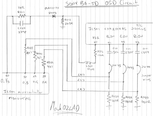
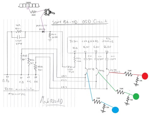
We'll start with the factory configuration of the On Screen Display RGB circuit. It's pretty standard really, RGB and Ys (Fast Blanking) going from the IC001 Micro controller to the IC301 Jungle chip
Analysis Of Existing Circuits
I have been unable to find a datasheet for the Sony CXA2154AS Y/C "Jungle" chip so I will attempt to reverse engineer using the existing On Screen Display circuitry.
For blanking from O_YS we have a 1KR resistor, MA111-TX Diode and a 3K3R resistor to ground. The microcontroller will be sending out a 5V signal (this is standard), The MA111-TX has a forward voltage of 1.2V, and we have a 1000-3300 Voltage divider. To calculate the blanking voltage...
(5.0 - 1.2) * 3300/(1100 + 3300) = 2.91V. Let's assume 3V is the required voltage for correct blanking
NOTE: There is also a O_YM circuit on the main schematic used for half tone, it is similar to the O_YS except it has a 6K8 instead of 1K. The O_YM circuit would result in (5.0 - 1.2) * 3300/(6800 + 3300) = 1.2V. We don't know the threshold for going from half tone to full tone blanking so we will stick to the 3V we calculated from the O_YS circuit
On each of the RGB lines we will have 5V coming from the micro controller, going through 4K7 resistors with 680R to ground. The resulting voltages going to the jungle can be calculated...
5.0 * 680 / (680 + 4700) = 0.63V.
Scart RGB standard is 0.7Vp-p so given the OSD RGB is at 0.63V we will assume that it is fine to put standard 0.7Vp-p into this jungle.
As always, we will put the Sync signal (Scart pin 20) through the Composite AV port (Yellow AV port), so that's it covered.
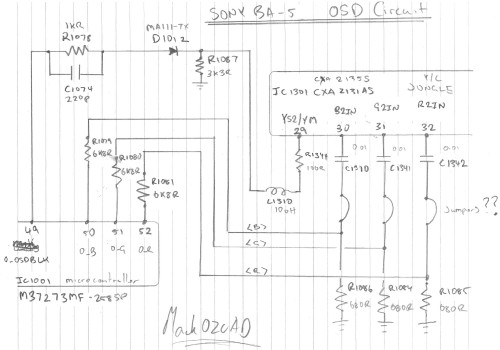
The Jumpers.....
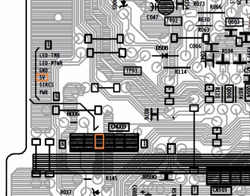
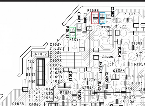
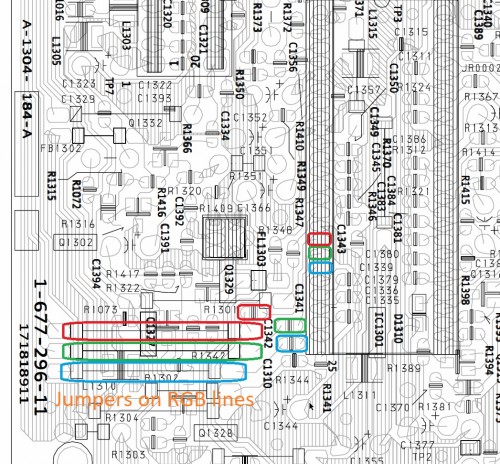
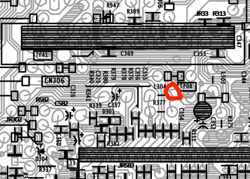
Jumpers make life easy, these ones will make great places to solder to, easier than surface mount resistor pads. The following jumpers are on the OSD RGB lines and would make a great solder point for the external RGB lines.
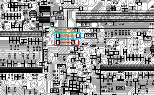
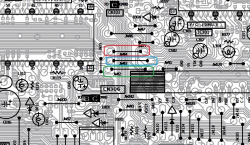
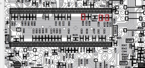
Jumpers can be seen in this photo
Simple Blanking Circuit
In a later post I'll add in a section about RGB blanking this TV from Scart Pin 16 but for now I'll just go with a very simple and pretty much foolproof circuit to force the TV into RGB blanking.
We need to inject 3.0V into the YS2 pin (RGB fast blanking pin) of the Jungle. My normal method is to grab a 5V source (which can normally be found in many places on a TV chassis) and then use voltage division to send the correct voltage to the blanking pin. We already have R012, a 3K3R, to ground on the blanking circuit. We will use this as the "R2" of a voltage divider, we will need to calculate the "R1".
The formula is
5 * R2 / (R2 + 3300) = 3.0
You can do the maths and find out that R2 is 2200 Ohm. Alternatively you can go to http://www.ohmslawcalculator.com/voltag ... calculator to work it out.
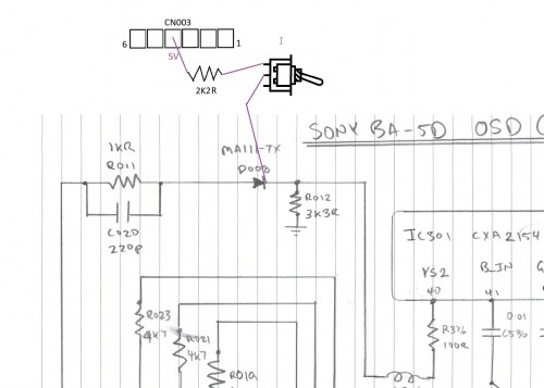
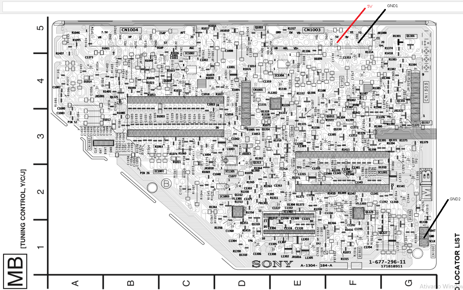
I did a quick search of the schematic for 5V sources, I found CN003. It's fourth pin has 5V running through it. Looks like a good one. (Notice there is ground next to it too...)
We will run a wire from this 5V source, through a 2K2R resistor to the outside leg of a SPDT switch. We will then run a wire from the centre leg of the switch to the leg of diode D008 that is closest the R012.
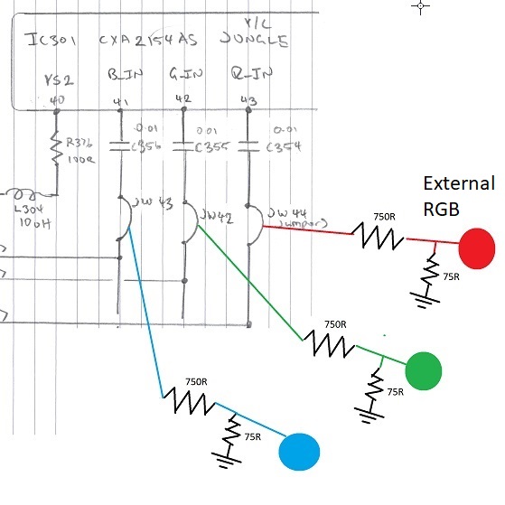
External RGB
Let's get to the fun part, getting our external RGB to come in whilst keeping our on screen display...
For reference here is the OSD Mix (Mux) diagram
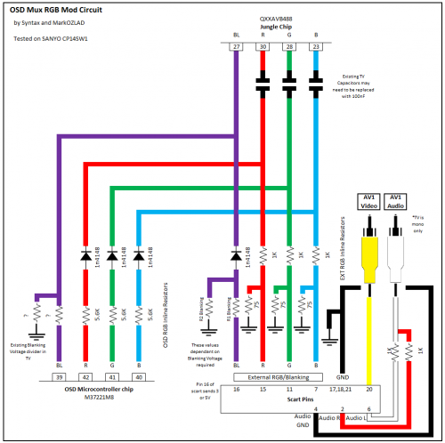
and here is the link to the OSD Mixing Calculator spreadsheet.
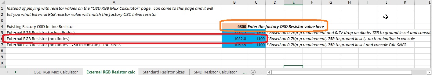
If you go to the sheet on the calculator spreadsheet named "External RGB Resistor Calc", we can calculate the resistance required on the external RGB lines in order to correctly terminate the OSD RGB.
The existing factory resistors are R019, R021 and R023. They are 4K7R so type in 4700 in the pink box. The value we are looking for is in the row "External RGB Resistor (no diodes)". The calculator will give you the exact value plus the nearest standard resistor size.
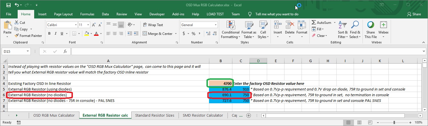
The calculator tells us to use 750R, it is also likely 680R will be fine too.
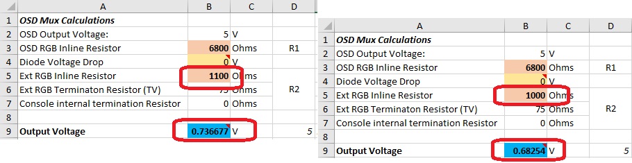
Double checking with the first sheet (OSD RGB Mux Calculator)...
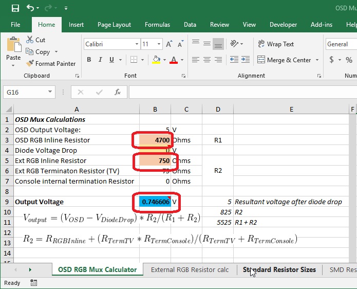
Using the 750R should yield us an OSD voltage level of around 0.75V which will be well within the tolerence of the jungle's RGB inputs (should handle at least up to 1V). Should be a nice bright OSD over top of our external RGB.
Our external RGB circuit will need to have the standard 75R termination resistor and a 750R on each of the RGB lines, these will then be soldered to the jumpers on each of the RGB circuits.
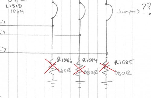
The external RGB lines will become the new "R2" of the On Screen Display voltage divider, because of this we will need to remove the existing "R2"'s, which are R020, R022 and R024. These are surface mounted resistors, please take care not to rip traces when removing them, maybe consult YouTube to work out how to remove them. (It's not my job to teach you how to remove them - I'm not that great at it myself!)
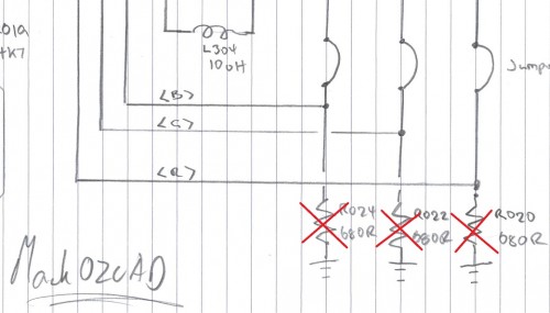
Now we can connect our external RGB lines with 75R ground termination and inline resistors.
Job done...


