Well, back there on page 3, there is talk about why a 4PDT would be more appropriate.
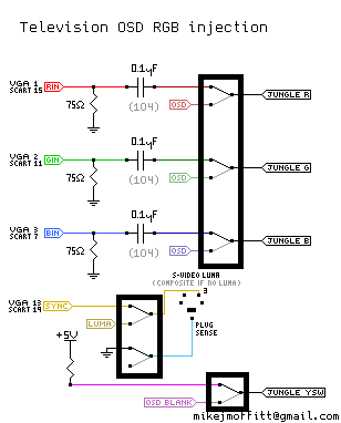
- why is a 6PDT switch used? Shouldn't a 4PDT suffice? I was under the impression that we're Hijacking R, G, B and injecting 5V. What are the other 2 switches for? Just to be safe, would it make sense to add a Diode on the 5V line to make sure that 5V doesn't feed into the regular RGB generator IC or will the switch suffice as protection?
But, If I'm looking at mikemoffitt's wonderful schematic at the OP, it looks like there's 6 switched points, doing it the way ^ you have drawn out. 6PDT would provide either isolated scart input in one switch position, or would isolate the scart with native input useable in the other position.
So, that is a good question - about signal reflections from the SCART port, if SCART sync->Y-pin is not switched.
:edit: obviously ground doesn't need to be switched and is probably better left continous from SCART input to chassis/frame/etc. So, guessing there's no harm in leaving sync unswitched and tapping Y anywhere ahead of the jungle, but obviously don't leave a SCART-connected device on when using the S-video port that uses the Y you tapped. I guess what you were looking at originally was wiring a separate external connector that would plug into composite or s-video inputs at the back of the TV for a simultaneous SCART+Sync connection? Sorry if I'm typing while thinking, but again also curious about whether SCART sync should be isolated when SCART is not in use.


