I'd like to give RGB modding a try for a couple TVs I own. I've gotten some soldering practice in with a few similar projects. Adding composite inputs to a couple old black and white TVs.
 https://www.youtube.com/watch?v=lgxGIwGnjng
https://www.youtube.com/watch?v=qCF4j0Q3kqc
https://www.youtube.com/watch?v=lgxGIwGnjng
https://www.youtube.com/watch?v=qCF4j0Q3kqc
Those two vids are of adding Composite to a cheap 12 inch B&W. So it's kinda simple compared to what I'm wanting to do next. Got a bag full of 75 ohm resistors and I'm sure I got the needed caps laying around. Got the mobo from a TV I had to EoL a couple months back that has many of it's components recycled in my other TVs. (mainly the capacitors since I knew they were still good the last time the TV worked. CRT busted, so it wasn't an issue on the mobo that killed that TV)
I have a soft modded Wii and a Sega Genesis (model 2). Both of which I believe support RGB (with the Genesis having an external sync available. Not sure on the Wii yet). I'm not sure about the Wii though. It can do RGB yes? I may have to force that video mode/make the Wii think it's a PAL console perhaps. (it's a NTSC/USA region Wii). It is soft-modded (and an older model that supports BootMii on Boot2!

) But the Genesis is straight forward and found that it has native RGB support exposed to it's AV port. Once I'm ready to try this I'll get the cable/parts for the Genesis and the parts I would need for the TV. The Wii I'd attempt next if I got a working RGB mod.
The 2 color TVs I own:
Sanyo with 20inch CRT (model DS20424) - Unfortunately one of those "Flat" CRT tubes so has that usual distortion issue that's visible with side scrolling games involving the edges of the screen.
-
Service Manual -
Philips with 27inch CRT (model 27PS50 B321 Chassis 7629) - This TV has an optional PIP module which is not present in my model. The connections for it appear to be there on the mobo. It might be using RGB for input but it may be component input though. Still new to reading schematics so not entirely sure on that. If tapping the PIP connections isn't an option there's either something related to ITV or I'd have to go the jungle IC route. (Jungle IC as in the connections to the neck board I assume?)
-
Service Manual -
Both these TVs are somewhat modern. The Sanyo being made in 2004 and the Philips one being a couple years older being made in 2002.
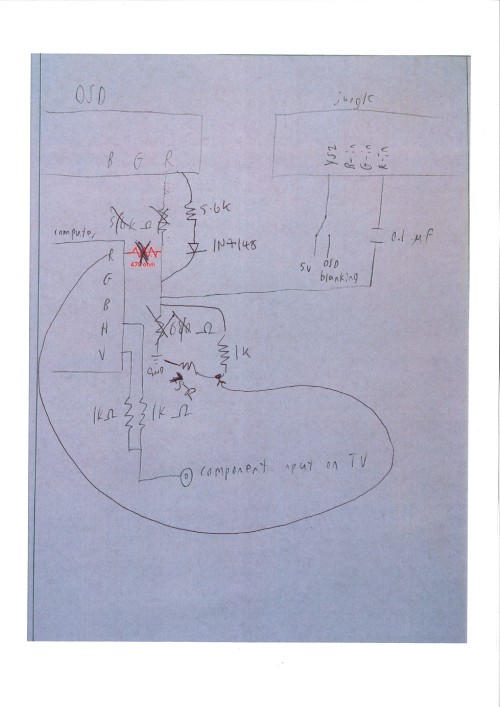
Both TVs have OSD/Captions generated from the same IC that drives the whole board pretty much and aren't on separate chips unfortunately. OSD on both units appear to be muxed into the video feed withen the IC and isn't exposed on the PCB in a way that would be possible to tap into.

So what are my options with these? After checking over the 2 service manuals, which one is the best candidate? I would prefer to do the Philips. They both have component inputs but both TVs don't support 480p and can only do 480i off those inputs. The Sanyo seems to have some flicker (which doesn't bother me that much) with 480i compenent. Fast moving scenes like explosion fx in Skyward Sword on my Wii has flicker. It seems to be deinterlacing the video feed? Haven't noticed interlacing with it in the short time I used it. It has a tired flyback I think. I replaced all the main caps that the main video side of the PCB depends on and I still notice a noticable screen size change when bright objects appear on screen. (life meter in Skyward Sword moves noticably when I rotate camera from dark to bright areas. It's annoying and drove me to replace it with the 27inch Philips unit I have now.
But the Philips TV doesn't do any form of deinterlacing....So yeah I can notice the scanline separation thing when things move side to side on screen. That kinda of bugs me so this TV I'd want to RGB mod just so I can get around that. (it does handle 240p pretty well. NES looks great on it and after accessing the service menu on both tvs, the overscan settings are to my liking.
)
I tried to get a Sony Trinitron but the one I found had a severe convergence issue where the corners were entirely unaligned with nearly a full inch of separation from R/G/B beams. I think the TV might have been dropped? Or the convergence strips (if it had any. Never bought that TV so didn't get the chance to take it apart.
) fell out/dislodged. That or the yoke became misaligned. Too bad, it's a Trinitron and was an older one too. Not one of those crappy flat CRTs that can have geometry issues as a result. It didn't have component inputs but being a Trinitron, it was definitly worth a serious RGB mod attempt. But the convergence was so bad I didn't want to risk putting $25 into something I might not be able to fix or would have to spend a lot more money getting parts for.
It was a 27incher and probably weighted in excess of 100+ pounds. Maybe a good thing I didn't get it and drop it attempting to bring it into the house. (and my crappy dresser seems to just barely handle holding up the Philips TV which is lighter then the Sony TV.
)
So I guess I'm stuck with what I have. I live in a **tty town where there's nothing interesting here and since I can't drive I can't go any significant distance to a larger city to find a better TV.
(and forget eBay. TVs in excess of 13+ inches become really expensive due to shipping.
)
So what are my options for modding the Philips/Sanyo? I have some caps and resistors and basic soldering equipment. Though I'll need some additional stuff like cables/adapters (maybe some SCART related stuff to I guess?)
EDIT:
Also I have a Sony KV13TR24 coming soon. So for that one I plan to tap into the RGB connections the close captioning module uses (since this is an older TV that has that on a separate chip) The only question I have is how to deal with sync. There is no S-Video or connection anywhere where a clean sync signal goes. So I expect I need to use the composite video for that. So when getting a SCART cable for my console I should get one with a "Sync on Composite" connection correct? I think SCART has that as standard and cables with "clean sync" need active sync stripping circuitry to do that. Pretty sure sync strippers isn't something I need here since the TV I'm going to RGB mod isn't a PVM and doesn't have a dedicated sync line anywhere on the PCB that I can see. (Also I couldn't find the exact service manual for the KV13TR24. I could only find a KV13TR28 manual. Is that close enough? I won't know for sure till I open her up and compare the the CC module. But the only real difference I see between the two is a slight change in the chassis design to account for an extra pair of AV jacks it has)
The TV I am getting only has one pair of AV jacks on the rear of the TV. The 28 model seems to be the same feature wise with everything else. Probably even has the same method of service menu entry.
My plan is to expose the RGB connections from the CC module to a DB9 connector I will mount near the AV jacks on the back. Then build a box that will accept a SCART cable. Not sure if I should put in 75 OHM resistors + the caps or not. I noticed the Genesis model 2 cable I want to get already has those. I might add the caps and resistors and use jumpers to bypass them for cables that already have that stuff. Don't really want to put the resistors/caps on the connections inside the TV. Want to reduce the amount of work I do inside the TV. Might not even disconnect the lines from the CC module. Seems like as long as CC is disabled in the menu there wouldn't by any issues just bridging in my RGB port. Unless it's recommended I separate them? I there's enough pins on a DB9 connector that I could put them on seperate pins and setup a simple termination jack with the wires bridge over to "connect" the CC module to the RGB input when I'm not using the RGB box.
I'd rather not drill any more holes into the case then nessecery so I don't want to mount any additional switches. Just the DB9 port.


