citrus3000psi wrote:
This QSB is not designed for PAL. Something else will have to be worked out for that. This design is more designed around me. I'm selfish

But I'm open to ideas. There are jumpers on the QSB to help control what does what.
Available Scenarios as of now:
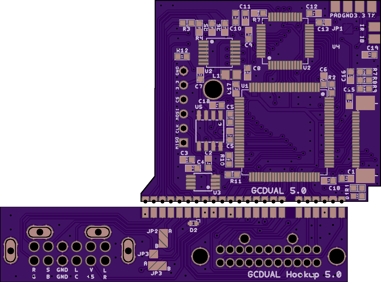
CSync wired to Mutliout CSync (JP2-A Jumped)
VSync Wired to Multiout Cysnc (JP2-B Jumped)
HSync Wired to Multiout Luma (JP3 Jumped)
Mode Wired to Multiout Chroma (JP4 A Jumped) (Component controlled by custom cable)
Mode Wired to Ground (JP4 B Jumped) (Component all the time)
If you jump anything to Chroma Or Luma you will have to cut traces or remove components.
If you install this to a PAL cube you will have to cut traces on the RGB/+12 lines or remove components. (Would you want this for a PAL, do PAL gamecubes output 480p RGB?)
If you need HSYNC/VSYNC Pads, I can add them back in there is room up top.
This solution isn't going to be for everybody. But I can add in more jumpers, to control if sync goes to Video/Luma.
The original board I have will be my first test. I wont get these new boards sent off until the existing proto is working. So that board won't be abandon. I can easily throw together a qsb that has pads to the multi out pins.
Hmm, well if your keeping both designs then it doesn't really matter, since I guess all it really needed was a separate MULTI OUT QSB (and even then a QSB is not strictly necessary, it just makes for an easier/neater install)
If your open to suggestions for the new design heres a few I can think of:-
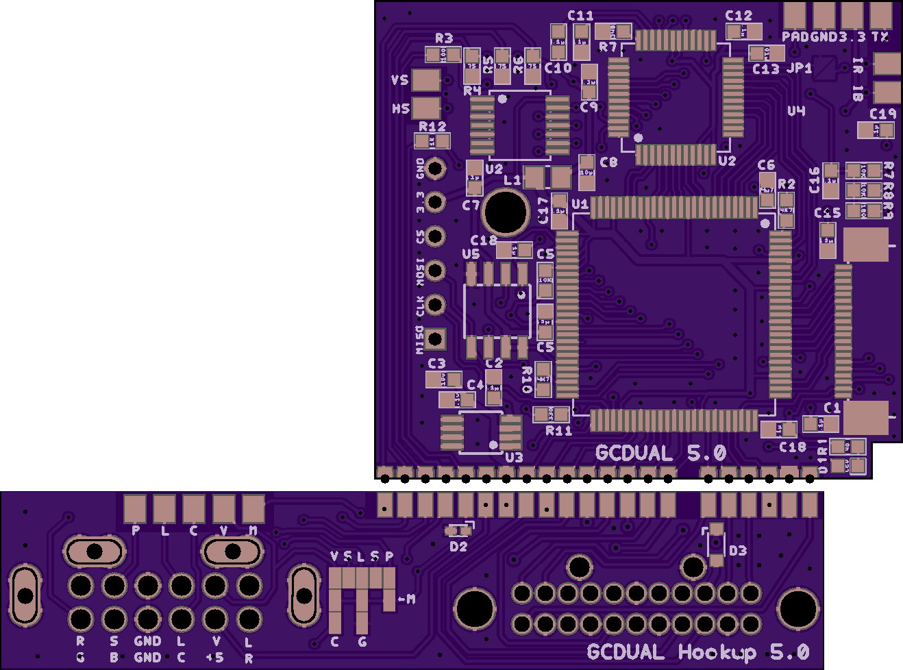
-If theres space extend the castellation pads for the analog signals on the main board and label them so that a manual wire install is still feasible when used in combination with a DIGITAL OUT only QSB.
-On the QSB have CSYNC connect to a jumper with A and B positions connected to MULTI OUT Pin 3 and Pin 9, so the installer can choose where CSYNC will be connected to (Obviously they would need to isolate the pin on the motherboard first if its already being used for +12V or Composite Video)
-Have jumpers to optionally connect the HSYNC and VSYNC signals to the Luma and Chroma pins, so you can choose to have either the stock S-Video, or RGBHV (Nice for PAL consoles since S-Video isnt even available/connected)
-Have an accessible 'Mode' switch pad like the original design, so that a manual RGB/YPbPr switch can still be installed if preferred. There are some nice switches which can fit through the rear vents so no case cutting is required:-
http://www.mmmonkey.co.uk/wordpress/wp- ... switch.jpg
-Just an idea, but after thinking about which pins on the MULTI OUT plug are really required, i'm not sure if its 'essential' to have two ground pins? (Pins 5 and 6) So instead perhaps you could have the 'Mode' pin optionally connected to MULTI OUT pin 6 by a jumper (The installer would need to isolate Pin 6 from GND before installing the QSB) Then set the firmware so that if the Mode pin is grounded it selects RGB, and if not it selects YPbPr. Its been a while since I looked into this, but as far as I can recall all official cables use both ground pins 5 and 6 (Not sure about third party cables) which would make RGB the default. Then to build a YPbPr cable you would just leave pin 6 disconnected. Hopefully that makes sense?
Anyway, just a few thoughts I had!


