Hi guys,
Trying to make an RGB cable for my SNES (NTSC version, not sure if 1CHIP) that will plug directly into my Sony PVM monitor, but have not found any guides on this. Want to skip the whole SCART/JP21 cable adapter mess and do it myself.
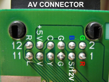
Using the pinout data from this website: http://www.gamesx.com/wiki/doku.php?id= ... ndomultiav
My understanding is that I can get CSYNC from pin 3 on the NTSC version, followed by RGB out of pins 1, 2 and 4 respectively. Pin 5 for ground, and pins 11 and 12 for Left and Right audio, respectively.
Please forgive my drawing skills, but the "schematic" is roughly this:
http://i.imgur.com/ECXn9l6.jpg
The 3 caps are 220uF with positive towards the console and all of them terminating in an RCA plug (I'll have BNC to RCA connectors installed on the PVM). Any issue with using one ground for all sources? Intuitively, I can't imagine any affect, but someone more learned may tell me otherwise.
What cable configuration is best to use for this? I can theoretically keep all grounds to one cable, with the split to each R/G/B input happening at the PVM point of connection, or I can utilize COAX cable with shielding and split the Ground contact at the SNES point of connection.
Anything else I missed?
I'm ignoring 5V and 12V pinouts on the SNES AV because I don't see why the PVM would need these.
DIY RGB Cables
-
Guspaz

- Posts: 3242
- Joined: Tue Oct 06, 2015 7:37 pm
- Location: Montréal, Canada
Re: DIY RGB Cables
If you're building a from-scratch custom cable just so that you can avoid using a SCART-to-BNC breakout cable, then you might as well have your cable go directly to BNC. I mean, you're building a cable from scratch in order to avoid using an adapter, but then you're going to go ahead and use adapters anyhow? Remember also what you're giving up in order to do this, however: the inability to use any sort of converter or upscaler in the future that uses SCART, and the inability to use SCART switches. You can't use component video switches because they won't have anything that can switch sync, unless your cable internally converted to sync-on-green. You might be able to use a crosspoint switch, but those are BNC too.
-
Honthro
- Posts: 6
- Joined: Fri May 20, 2016 2:56 pm
Re: DIY RGB Cables
Thanks for the thoughts. I'm treating this as a hobby project and if I want to go down the rabbit hole of multiple systems with multiple inputs using SCART switches with upscalers, then I will consider it. Currently, this is just something fun since I only got the PVM a couple of days ago, and the system itself only yesterdayGuspaz wrote:If you're building a from-scratch custom cable just so that you can avoid using a SCART-to-BNC breakout cable, then you might as well have your cable go directly to BNC. I mean, you're building a cable from scratch in order to avoid using an adapter, but then you're going to go ahead and use adapters anyhow? Remember also what you're giving up in order to do this, however: the inability to use any sort of converter or upscaler in the future that uses SCART, and the inability to use SCART switches. You can't use component video switches because they won't have anything that can switch sync, unless your cable internally converted to sync-on-green. You might be able to use a crosspoint switch, but those are BNC too.
As for your comment on RCA vs BNC connectors, you're right, there's no real reason for it, other than I'm used to working with RCA connectors for cable building. I'll probably do straight BNC connectors now that you mention it. But it shouldn't alter the schematic significantly, right?
-
CkRtech

- Posts: 668
- Joined: Mon Aug 27, 2012 9:30 pm
- Location: Seattle, WA
Re: DIY RGB Cables
Haha. It is a mess.Want to skip the whole SCART/JP21 cable adapter mess and do it myself.
If you start making your own cables, you have the absolute freedom to do whatever you want with the level of quality you want. VGA and BNC are really good connection options for matrix switches. Many monitors use BNC connections, and VGA<->BNC cables are easy to come by - largely in part due to projectors here in NTSC-land. I make my own cables and use a 16 port VGA switch (with 1/8" audio jacks built-in), myself. As far as BNC/RCA on monitors - you can use adapters where needed, but as Guspaz said - you are going from scratch, so you can terminate any way that you want.
You can use tantalum caps and fit them inside the SNES connector. I believe I tied my video to one ground pin and audio to the second ground pin since there were two available at the multiout.
I wouldn't worry at all regarding converter/upscalers and SCART. There really isn't a reason to put such a bulky connector on an upscaler as it takes up a ridiculous amount of space. Micomsoft definitely dropped it (technically the JP21 connector) with their move to the xrgb mini from the previous series. The OSSC has a VGA connector as well as SCART, and there is a bit of fine print on it as far as VGA vs SCART re: standard def sources, but it is also work-in-progress at the moment. I suppose you could build a small adapter should you want to take advantage of the filtering circuit in the OSSC's SCART connection after your primary cable or switch switch setup should you feel it is necessary.
At the moment, it sounds like you are set on the Sony PVM as your display, anyway.
-
mvsfan
- Posts: 1209
- Joined: Sat Oct 06, 2012 12:24 am
Re: DIY RGB Cables
you can use a component switch like the joytech js965c because it also has a composite jack that switches at the same time that you can use for Sync.
-
Guspaz
- Posts: 3242
- Joined: Tue Oct 06, 2015 7:37 pm
- Location: Montréal, Canada
Re: DIY RGB Cables
Yes, a component switch with simultaneous composite switching will work. But digital audio (an orange RCA jack) will not work for sync, at least with Audio Authority switches.
-
BazookaBen

- Posts: 2159
- Joined: Thu Apr 17, 2008 8:09 pm
- Location: North Carolina
Re: DIY RGB Cables
When I made my own cables I made it even simpler by terminating in 1 HD15 connector and 2 rca plugs (for stereo). Then I just run a VGA>BNC cable to my PVM and a normal rca cables to my audio receiver.
-
Shuco13
- Posts: 147
- Joined: Fri Aug 01, 2014 6:15 am
-
CkRtech
- Posts: 668
- Joined: Mon Aug 27, 2012 9:30 pm
- Location: Seattle, WA
Re: DIY RGB Cables
A few of us have. Are you looking to start making some cables? What sort of mini-din? Specific to a console? You looking to make some direct to framemeister cables? (i.e. SNES multi to 8 pin mini din)
-
cr4zymanz0r

- Posts: 358
- Joined: Sat Oct 19, 2013 6:36 am
Re: DIY RGB Cables
I previously eliminated SCART from my setup. Documented it in an older post: http://shmups.system11.org/viewtopic.php?f=6&t=52476
-
korpse413

- Posts: 193
- Joined: Mon Sep 15, 2014 11:23 pm
- Contact:
Re: DIY RGB Cables
Wow man awesome work! Just checked out the setup Imgur. I love seeing peoples gaming setups, its like a weird fetish of mine lol..cr4zymanz0r wrote:I previously eliminated SCART from my setup. Documented it in an older post: http://shmups.system11.org/viewtopic.php?f=6&t=52476
I've been getting better with the soldering iron, I should pry open my scarts and see how they look. Although, its like they say, if it ain't broke..
-
Shuco13
- Posts: 147
- Joined: Fri Aug 01, 2014 6:15 am
Re: DIY RGB Cables
Exactly. From what I saw only 6 lines need to be wired, audio can be transmitted externally.CkRtech wrote:You looking to make some direct to framemeister cables? (i.e. SNES multi to 8 pin mini din)
...aka 12345
-
Einzelherz

- Posts: 1279
- Joined: Wed Apr 09, 2014 2:09 am
Re: DIY RGB Cables
A slightly easier way of doing this, assuming you can get the male connectors for each system, is to buy a six wire xbox cable and cut it apart. I used one for the SCART to RCA adapter that I run all of my RGB consoles through to my PVMS (via a componen switch). They're usually only a few bucks on ebay and they have the nice color setup of RGBYRW. I'm not sure how you'd account for the necessary transistors and such, however.
-
Honthro
- Posts: 6
- Joined: Fri May 20, 2016 2:56 pm
Re: DIY RGB Cables
UPDATE: Finished my cables. Since no one said anything about my schematic, I assumed it was fine.
Here are the results: http://imgur.com/a/KC9d4
Bought two cables of 6 feet each with two female BNC connections on the end, and cut each in half. Figured this was easier and takes care of shielding for each cable. That and I didn't want to wire BNC cables without a proper crimper.
Took apart an N64 RF modulator because I needed that SNES multi connection and this was the cheapest way. Had to make a bunch of awful looking holes in the RF housing for the cables. In retrospect, the 4 BNC cables was probably overkill since the cable is so thick and unwieldy. Audio L and R were connected to female RCA plugs which I use to plug into my amp.

-
bobrocks95

- Posts: 3663
- Joined: Mon Apr 30, 2012 2:27 am
- Location: Kentucky
Re: DIY RGB Cables
Glad you went with straight BNC. If you ever add a switch, BNC switches are painless, cheap, and work well, which are the exact opposite of most SCART switches since they were only a consumer standard.
Looks good, not sure how you'd be able to spot any potential issues.
Looks good, not sure how you'd be able to spot any potential issues.
PS1 Disc-Based Game ID BIOS patch for MemCard Pro and SD2PSX automatic VMC switching.
-
Guspaz
- Posts: 3242
- Joined: Tue Oct 06, 2015 7:37 pm
- Location: Montréal, Canada
Re: DIY RGB Cables
Maybe ceramic caps would let you get them small enough to fit in there?
-
creib
- Posts: 15
- Joined: Fri Dec 01, 2017 12:31 am
Re: DIY RGB Cables
Figured id bump an oldie rather than start a new
id like to make a few custom SNES RGB cables. i currently have all the cabling needed but going though scart. Since i only play snes i figured id simplify, have some fun, and at the same time make the lengths i want for a clean install. i crimp BNC fairly regularly at work so the cable making part will be easy, but was hoping to have a few questions answered
heres what im working with
Super Famicom 1chip-03 w/ Voultars THS7374 board
SNESmini w/ Voultars THS7374 board
JVC DT-V1910CGU
XRGB-mini Framemeister feeding my civilian TV
id like to make
direct SNES AV connector to RGBs BNC and a mono audio RCA (JVC has only a mono RCA input)
direct SNES AV to framemister 8pin mini din
my questions:
1: to make mono audio feed is it as simple as wiring pins 12 (right audio) and 11 (left audio) together?
2: with voultars board are caps (220uf 6.3v?) still needed on the RGB lines?
if the caps are needed can anyone recommend ones that are small enough to fin inside a nintendo multiout housing?
3: is a resistor (330ohm 1/4w?) needed on the CSYNC line? on both consoles voultars board the TTL strap is NOT bridged.
any harm in adding the resistor anyway?
4: what, if anything, do i connect to the framemiester pin5 to on the snes AV multiout?
thanks!
for reference