EDIT:
My question has been answered.
If anyone is interested in trying the boards I made here are the links:
Sync Stripper: https://easyeda.com/hotdog6394/SYNC_STRIPPER-rHgecawur
N64 RGB AMP: https://easyeda.com/hotdog6394/THS7314_ ... -6YtnFzR9r
SNES MINI RGB/S-Video AMP: https://easyeda.com/hotdog6394/SNES_MIN ... -GsfPNnXV6
TURBO DUO RGB AMP: https://easyeda.com/hotdog6394/PCE_RGB_ ... -y5hfPbwu4
No idea if they will work. I tried to use only SMD components. With the SNES mini I don't know if the 220uf capacitor needs to be polarized or not.
Will this PCB design work for a PCE RGB amp ?
-
the_crayon_king

- Posts: 45
- Joined: Thu Nov 26, 2015 2:47 pm
Will this PCB design work for a PCE RGB amp ?
Last edited by the_crayon_king on Sat Feb 27, 2016 1:54 pm, edited 1 time in total.
-
ApolloBoy

- Posts: 939
- Joined: Sat Jan 28, 2012 7:17 pm
Re: Will this PCB design work for a PCE RGB amp ?
Yes, but there are much better options nowadays, like the THS7314-based amp (http://nfggames.com/forum2/index.php?topic=4822.0) or Tim's upcoming AVDRIVER amp.
-
keropi

- Posts: 323
- Joined: Sat Sep 20, 2008 9:33 am
- Location: Ioannina , Greece
Re: Will this PCB design work for a PCE RGB amp ?
I get great results with the transistor-based RGB/Sync amp posted by the OP. I do plan to replace it though with Tim's avdriver once it's available - it just seems a better and more precise solution. Plus it has onboard audio amp - something that is needed at least on PCE consoles so you don't have to turn the volume way up on your tv set.
I have seen some other THS7314 based amps but what I did not like about them is that they don't have C-SYNC amplification, it's a must to use IMHO.
The one ApolloBoy posted should be nice for other stuff but not optimal for PCE IMHO because of the way it treats C-Sync. The amp uses a LM1881 to extract it from composite (great if the host device does not offer the option) but the PCE has a dedicated c-sync output that only needs amplification.
On the other hand once could argue that a THS7314 based amp should be more precise/good than a bunch of transistors and resistors
Well, that's my 2 cents anyways... , my money is on Tim's amp - it just combines all the good stuff in one package.
I have seen some other THS7314 based amps but what I did not like about them is that they don't have C-SYNC amplification, it's a must to use IMHO.
The one ApolloBoy posted should be nice for other stuff but not optimal for PCE IMHO because of the way it treats C-Sync. The amp uses a LM1881 to extract it from composite (great if the host device does not offer the option) but the PCE has a dedicated c-sync output that only needs amplification.
On the other hand once could argue that a THS7314 based amp should be more precise/good than a bunch of transistors and resistors
Well, that's my 2 cents anyways...
-
Asbrandt
- Posts: 45
- Joined: Thu Oct 24, 2013 6:09 pm
Re: Will this PCB design work for a PCE RGB amp ?
According to an older post from Viletim I encountered, PC Engine has a rather strange CSync signal, it's 5v High and 4.2v Low, so it's not straightforward to get a buffered 5vpp signal out of.keropi wrote:I have seen some other THS7314 based amps but what I did not like about them is that they don't have C-SYNC amplification, it's a must to use IMHO.
I believe the schematic above makes a buffered 0.6vpp signal, 0.3 after the termination resistors, for the sync output, which is unfortunately insufficient for the Extron interface I use.
I'd be rather curious to know what approach viletim took to produce the TTL sync option on the AV-DRIVER, and if the TG16 has the same "issue."
-
the_crayon_king
- Posts: 45
- Joined: Thu Nov 26, 2015 2:47 pm
Re: Will this PCB design work for a PCE RGB amp ?
I was under the impression that the transistor based method was better than the 7314 amp design.
I made this for NS1 N64s that need c-sync. Would it work for the PCE as well ?
I made this for NS1 N64s that need c-sync. Would it work for the PCE as well ?
-
Asbrandt
- Posts: 45
- Joined: Thu Oct 24, 2013 6:09 pm
Re: Will this PCB design work for a PCE RGB amp ?
I can only see a placeholder image in your links, I would assume the site you're using doesn't allow linking in the manner you're using or something.
-
the_crayon_king
- Posts: 45
- Joined: Thu Nov 26, 2015 2:47 pm
Re: Will this PCB design work for a PCE RGB amp ?
It was set to private., whoops. It's open now.
PCE transistor RGB AMP
https://easyeda.com/hotdog6394/PC_Engin ... -8Cca86rpn
N64 NS1 RGB Amp with stripper:
https://easyeda.com/hotdog6394/N64_RGB_ ... -HtqomWiSd
I didn't save the schematic so ill have to remake that part but its just a ths7314 and a lm1881.
@keropi: I heard the LM1881 can act as a sync booster and stripper.
If anyone knows of a chip that does both that would be great.
I haven't read up on Tim's av driver I'll have to check it out.
I was trying to make 2 or 3 boards to fit all my needs. SNES mini rgb, N64 RGB, and PCE RGB.
I build all these by hand and a board would cut out alot of potential for error.
The board above for the N64 might work, and I suppose even if it doesn't boost c-sync correctly then I can just get it from the composite video.Asbrandt wrote:According to an older post from Viletim I encountered, PC Engine has a rather strange CSync signal, it's 5v High and 4.2v Low, so it's not straightforward to get a buffered 5vpp signal out of.keropi wrote:I have seen some other THS7314 based amps but what I did not like about them is that they don't have C-SYNC amplification, it's a must to use IMHO.
I believe the schematic above makes a buffered 0.6vpp signal, 0.3 after the termination resistors, for the sync output, which is unfortunately insufficient for the Extron interface I use.
I'd be rather curious to know what approach viletim took to produce the TTL sync option on the AV-DRIVER, and if the TG16 has the same "issue."
-
Asbrandt
- Posts: 45
- Joined: Thu Oct 24, 2013 6:09 pm
Re: Will this PCB design work for a PCE RGB amp ?
Yes, it works now.the_crayon_king wrote:Is this better ?
For the PC Engine, I would consider the LM1881 a valid approach due to the very strange voltages you'll encounter from it's CSync line.
But you've completely neglected to include a termination resistor, which means when plugged into a TV it would experience a heavy load, way more than the mere 5ma the LM1881 is designed for.
I've been told the LM1881's output will just drop output voltage to compensate until it's back to 5ma but my gut feeling does not like relying on this this at all. It takes 1kOhm of resistance to drop the load to 5ma at 5v, but I'm not sure how this may affect things such as signal reflection, a more knowledged individual would need to comment, although Viletim did at one point reccomend 470Ohm, so perhaps that wouldn't be an issue when the termination resistor is stronger than the load resistor?
However, you could simply duplicate the old transistor design's CSync driver if you know you won't need higher voltage sync, such as if you don't use any Extron devices, etc. It also neglects to show the 75ohm termination resistor that it would need.
As for the THS7314 build, the PC Engine (but not the TurboGrafx-16 from what I've been told) outputs a higher voltage than normal, 0.864vpp instead of 0.7vpp, so you'll need to have both the termination resistors -and- additional pulldowns after them, using a 91 terminator followed by a 390 pulldown, both 1% tolerance, is what was recommended to me.
In addition, the THS7314 wants a relatively controlled amount of DC bias, 82nf caps in series on the input to block the existing DC offset, followed by a 3.6MOhm pullup to introduce the controlled bias, as the RGB lines do not have a sync signal with which to trigger the Sync Tip Clamp circuit.
For the N64, it's commonly reccomended to tap RGB from the existing DC blocking caps on the system leading into the encoder, so they wouldn't be needed for that system, but the 3.6MOhm pullups would be.
For the SNES Mini, you actually do not need any RGB amp at all, the encoder is the same as the normal systems' so you would only need wires and 75ohm resistors, but some chose to use a THS7314 anyway, because it happens to do a strong job of filtering out the infamous vertical bar the SNES is plagued with.
Regarding CSync, for the N64 and SNES Mini (and Genesis too), you can simply use a logic level buffer such as the SN74LVC1G34DBVR, as the signals on the board are already correct logic levels and simply need a stronger driver. Mind the need for a termination resistor still, however.
-
CkRtech

- Posts: 668
- Joined: Mon Aug 27, 2012 9:30 pm
- Location: Seattle, WA
Re: Will this PCB design work for a PCE RGB amp ?
I use Tim's AV Driver, and it has an input/output for csync as well as a jumper to control if you want 75 ohm terminated or TTL. When I installed it and tested it, it looked great with 75 ohm termination. After that, I hooked it up to my VGA switch with the jumper set for TTL - also looked great.
I highly recommend the AV Driver for PC Engine amplification. It is highly versatile for amp strength, gives you two options for csync output, and also has an audio amp should you need it.
I highly recommend the AV Driver for PC Engine amplification. It is highly versatile for amp strength, gives you two options for csync output, and also has an audio amp should you need it.
-
the_crayon_king
- Posts: 45
- Joined: Thu Nov 26, 2015 2:47 pm
Re: Will this PCB design work for a PCE RGB amp ?
Does it boost audio as well ? Also do you know the price ?CkRtech wrote:I use Tim's AV Driver, and it has an input/output for csync as well as a jumper to control if you want 75 ohm terminated or TTL. When I installed it and tested it, it looked great with 75 ohm termination. After that, I hooked it up to my VGA switch with the jumper set for TTL - also looked great.
I highly recommend the AV Driver for PC Engine amplification. It is highly versatile for amp strength, gives you two options for csync output, and also has an audio amp should you need it.
Anyway part of me just wanted to make my own boards not only for price control but also the idea fascinates me.
Especially if I could take something that I have been building over and over by hand (snes mini and n64 rgb amps) and cut down the process.
I believe making a SNES mini and N64 rgb amp w/ sync stripper is well within my realm of capabilities.
However I don't know enough to go much further with the PCE.
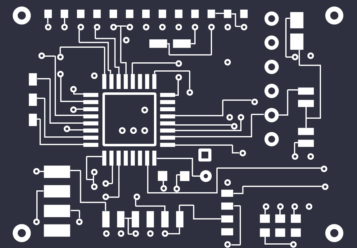
That said I made this off of a THS 7314 schematic for RGB, added the LM1881 for sync, and finally a TDA2822M for audio:
https://easyeda.com/hotdog6394/PCE_RGB_ ... -y5hfPbwu4
I will keep redesigning it till I get something functional. I will have to learn more about the whole processes. I don't really understand coupling or pulldown and many other thing and that's something I will have to learn on my own time.
-
low_budget
- Posts: 77
- Joined: Wed Nov 27, 2013 3:05 pm
Re: Will this PCB design work for a PCE RGB amp ?
I see many good Turbografx RGB mods out there now. I remember just a couple years ago there really were no RGB kits for Turbografx, you just had to build a circuit on prototype board.
I am working on building some more TGezRGB boards.
They'll be available again in March.
The TGezRGB and PCezRGB are the easiest to install RGB mod boards. They solder directly to the bottom of the system's motherboard over the expansion port pins of a Turbografx or PC Engine. It uses a THS7314 for RGB amplification and a LM1881 for driving the sync. The only wired connections are from the mod board to the A/V out jack.
http://www.lowbudgetify.com/turbografx- ... e-rgb.html
Last edited by low_budget on Fri Feb 26, 2016 10:32 pm, edited 1 time in total.
-
the_crayon_king
- Posts: 45
- Joined: Thu Nov 26, 2015 2:47 pm
Re: Will this PCB design work for a PCE RGB amp ?
I have a turbo duo. Your board does look perfect for the other versions though.low_budget wrote:I see many good Turbografx RGB mods out there now. I remember just a couple years ago there really were no RGB kits for Turbografx, you just had to build a circuit on prototype board.
I am working on building some more TGezRGB boards.
I hope to have these available again in April.
The TGezRGB and PCezRGB are the easiest to install RGB mod boards. They solder directly to the bottom of the system's motherboard over the expansion port pins of a Turbografx or PC Engine. It uses a THS7314 for RGB amplification and a LM1881 for driving the sync. The only wired connections are from the mod board to the A/V out jack.
http://www.lowbudgetify.com/turbografx- ... e-rgb.html
I think I can design the circuitry I need to with do the boards I am working on.
Do you know of a vendor that will place components or do I need to do it by hand ?