PCE Duo Issue
-
Thamiel
- Posts: 180
- Joined: Wed Feb 15, 2012 2:21 am
PCE Duo Issue
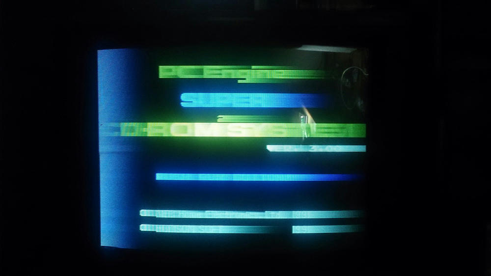
Hey guys, having an issue with my RGB modded Duo. Getting extreme smearing to the right and have no idea whats causing it. Any ideas where I should start looking?
-
kamiboy
- Posts: 2000
- Joined: Sat Sep 04, 2010 4:40 pm
- Location: Denmark
Re: PCE Duo Issue
Start by looking at the RGB cable.
-
Pasky

- Posts: 699
- Joined: Mon Oct 21, 2013 3:58 am
Re: PCE Duo Issue
That's a weak sync signal. If you're grabbing csync straight off the board it's only at about 0.2-0.3vpp and it will end up looking like that. You need to boost the sync by either running the CSYNC through a lm1881 or stripping it from composite with a lm1881.
-
Thamiel
- Posts: 180
- Joined: Wed Feb 15, 2012 2:21 am
Re: PCE Duo Issue
Thanks for the replies guys, I have no idea which RGB mod was used for this one. A friend of mine did it for me, wont be able to check the console until I grab a torx screwdriver tomorrow.
I did crack open the cable though for a look and tested the continuity.
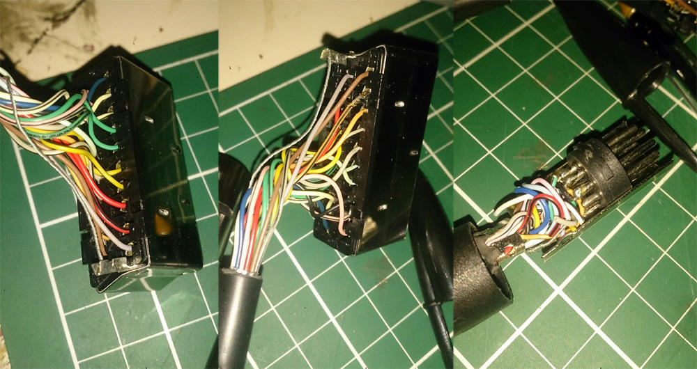
Pinout seems to be this.
<DIN8 - SCART>
6 - 15
8 - 11
7 - 7
1 - 2
4 - 20
2 - 18
5 - 6
3 - Nothing
I did crack open the cable though for a look and tested the continuity.
Pinout seems to be this.
<DIN8 - SCART>
6 - 15
8 - 11
7 - 7
1 - 2
4 - 20
2 - 18
5 - 6
3 - Nothing
-
kamiboy
- Posts: 2000
- Joined: Sat Sep 04, 2010 4:40 pm
- Location: Denmark
Re: PCE Duo Issue
Where are the 220uF caps? Perhaps your friend put them inside the console as part of the amp circuit.
-
Thamiel
- Posts: 180
- Joined: Wed Feb 15, 2012 2:21 am
Re: PCE Duo Issue
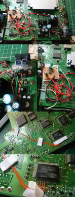
Grabbed myself a Torx set and cracked open the Duo. What i'm seeing is not filling me with confidence.
Click for high res.
Click for high res.

-
RGB32E

- Posts: 1400
- Joined: Thu Nov 05, 2009 12:50 am
Re: PCE Duo Issue
Is this the work of Drakon? Only salvageable thing about this mod is the 4 wires soldered to the Hu6260! Install an AV Driver and get a quality cable made. I thought the standard RCA/RGC cables were awful?! 
Hot glue, wires are stripped to far, and no shrink tubing.
Hot glue, wires are stripped to far, and no shrink tubing.
-
Thamiel
- Posts: 180
- Joined: Wed Feb 15, 2012 2:21 am
Re: PCE Duo Issue
I don't even really know what to do about this, I'm a novice at soldering but I think even me attempting it would be cleaner.
Guess it's time to pick up a few soldering supplies, watch some YouTube videos and get to work. Can't think of anyone I'd trust here in Australia to do this properly.
Guess it's time to pick up a few soldering supplies, watch some YouTube videos and get to work. Can't think of anyone I'd trust here in Australia to do this properly.
-
RGB32E
- Posts: 1400
- Joined: Thu Nov 05, 2009 12:50 am
Re: PCE Duo Issue
Youtube videos on the specific mod won't help you. You need one of Tim Worthington's AV-DRIVER PCBs for a proper RGB mod. Contact him and one of his recommended installers and you should be set.
http://etim.net.au/shop/shop.php?sc_page=105
http://etim.net.au/shop/shop.php?sc_page=105
-
Thamiel
- Posts: 180
- Joined: Wed Feb 15, 2012 2:21 am
Re: PCE Duo Issue
Oh I meant more just for cleaning up the soldering and whatnot, I should be ok just soldering to some pads and heat shrinking.
I'll see if any of them are that active at the moment, a lot of the Aussie guys have quietened down.
I'll see if any of them are that active at the moment, a lot of the Aussie guys have quietened down.
-
Thamiel
- Posts: 180
- Joined: Wed Feb 15, 2012 2:21 am
Re: PCE Duo Issue
Long overdue update. Finally tackled a full clean up and recap of my Duo and installed Tims AV Driver. Did the jailbar fix as well, the video output is fantastic!
Having a little audio issue though, the headphone jack has both right and left channels but the AV port only has the left channel. Been poking around with the multimeter and cant seem to find a broken trace. Is there somewhere i can tap the audio from and use the AV Drivers amp instead?
Sent from my SM-G950F using Tapatalk
-
Thamiel
- Posts: 180
- Joined: Wed Feb 15, 2012 2:21 am
Re: PCE Duo Issue
Any ideas guys? Would love to finish this one up.
Sent from my SM-G950F using Tapatalk
Sent from my SM-G950F using Tapatalk
-
Thamiel
- Posts: 180
- Joined: Wed Feb 15, 2012 2:21 am
Re: PCE Duo Issue
Sorry to keep bumping guys, think i may have found the issue. Im only getting 2.4v on the input pin of the M51131L IC. Datasheet says it should be 8-15v. Can anyone confirm? Slightly paranoid about frying the IC.
Sent from my SM-G950F using Tapatalk
Sent from my SM-G950F using Tapatalk