Not getting power on Kick 3 on CPS2

The place for all discussion on gaming hardware
Post Reply
retrogamingjohnny
Posts: 60
Joined: Thu May 15, 2014 4:35 am
Location: United States

Not getting power on Kick 3 on CPS2

Post by retrogamingjohnny »

Hey guys how's it going? Today I tried to hook up the remaining kick buttons for my CPS2 board. I am using a supergun that uses DB15 Neo Geo button connection. I connected the Kick harness to the proper P1 4, 5, and 6 buttons, but can't get button 6 to work. There's only 4 wires remaining on the Neo Geo DB15 cable that I haven't connected to any buttons. Upon checking the power, none of the 4 wires have any reading whereas all other read near 5v. Then I checked the power on the P1 port of the supergun, I found a few pins that have no reading. The one I am interested is pin 2 which is button 6 according to this diagram

Image

This is some shots of the supergun
Front:
Image

Back:
Image

So if you guys know how I can get power to the remaining wires, I'll much appreciate it. Currently I can get all Neo Geo, and Mortal Kombat 2 buttons to work, but I can't get button six to work on Capcom games. I'll appreciate any help. Thanks.
User avatar
RGB
Posts: 526
Joined: Sat Aug 04, 2007 3:11 pm
Location: Europe

Re: Not getting power on Kick 3 on CPS2

Post by RGB »

Have you got the CPS2 kick harness ?
retrogamingjohnny
Posts: 60
Joined: Thu May 15, 2014 4:35 am
Location: United States

Re: Not getting power on Kick 3 on CPS2

Post by retrogamingjohnny »

RGB wrote:Have you got the CPS2 kick harness ?
Yes sir. After connecting the kick harness I got kick 1 and 2 working, but can't get kick 3 to work. There are 4 wires from the DB15 cable that are unused and there is no power coming from them. Then I checked the controller port on the supergun and there's no power on those pins.

Namely pins 2,3,9,10 aren't getting any power, whereas the rest get around 5v. I don't know why.
Image

I was thinking about using a jumper to connect pin 8, which is +5v to pin 2 which is button 6 to power kick 3. Will that work or will that cause damage?
retrogamingjohnny
Posts: 60
Joined: Thu May 15, 2014 4:35 am
Location: United States

Re: Not getting power on Kick 3 on CPS2

Post by retrogamingjohnny »

Ok since no one has come up with any ideas, I figured a temporary solution although not ideal and will replace it as soon as I figure a better way.
As you can see, I have connected wiring for P1-4 and P1-5 of the CPS2 kick harness to the corresponding connectors B4 and B5 on P1 side of the supergun. Oddly, connecting P1-6 to B6 doesn't do anything. There's no power on the remaining 4 wires at the end of the DB15 cable.
Image
So what I did was to connect P1-6 of the kick harness to one of the receptors on the female side of the DB15 that is linked to one the remaining unused wires at the end of the cable so I can power kick 3. The thing is there is no way of telling which wire belongs to which pin on the DB15 since there's no instructions provided and it is no color coded.
Image
Of course this is not ideal. It will eventually break the wire upon repeated disconnection. If anyone has a more practical solution that does not involve wiring the kick harness directly to the buttons on the joystick or physically modifying the supergun, I am all ears. The reason I don't want to connect the kick harness directly to the joystick is because there is already a cable that goes to the controller port and having any more wires hanging makes it sloppy.
User avatar
CkRtech
Posts: 668
Joined: Mon Aug 27, 2012 9:30 pm
Location: Seattle, WA

Re: Not getting power on Kick 3 on CPS2

Post by CkRtech »

Just looking at the pictures, there should be no reason that the kick harness shouldn't work well with your supergun as they have the screw terminals right there with connections to each of the db-15 connector. If you do a continuity check on the B6 terminal and the appropriate pin on the DB-15 (button 2 on your label) and get continuity, then you should be fine.

No need to worry about power at all.

For testing, you could jam a wire into the GND screw terminal, power up your game, and use the ground wire to short to the various wires on your kick harness. If you short P1-4 to GND, P1-5 to GND, and P1-6 to GND, the test screen or player should show those buttons getting pressed each time you ground them. If you get some to work but not others, check your kick harness wiring.

EDIT: Hmm...actually, you are showing a white wire for your P1-6. According to the charts I see online, a CPS2 typical wire color is orange for P1-6. Colors don't really matter so much as pinouts because anyone can create a kick harness and use whatever colored wires you want...but you may want to use that ground testing I mentioned to test each of the wires from your kick harness.

Image
retrogamingjohnny
Posts: 60
Joined: Thu May 15, 2014 4:35 am
Location: United States

Re: Not getting power on Kick 3 on CPS2

Post by retrogamingjohnny »

CkRtech wrote:Just looking at the pictures, there should be no reason that the kick harness shouldn't work well with your supergun as they have the screw terminals right there with connections to each of the db-15 connector. If you do a continuity check on the B6 terminal and the appropriate pin on the DB-15 (button 2 on your label) and get continuity, then you should be fine.

No need to worry about power at all.

For testing, you could jam a wire into the GND screw terminal, power up your game, and use the ground wire to short to the various wires on your kick harness. If you short P1-4 to GND, P1-5 to GND, and P1-6 to GND, the test screen or player should show those buttons getting pressed each time you ground them. If you get some to work but not others, check your kick harness wiring.

EDIT: Hmm...actually, you are showing a white wire for your P1-6. According to the charts I see online, a CPS2 typical wire color is orange for P1-6. Colors don't really matter so much as pinouts because anyone can create a kick harness and use whatever colored wires you want...but you may want to use that ground testing I mentioned to test each of the wires from your kick harness.

Image

I want to thank you for mentioning the continuity check as I didn't know about it and it's really handy for figuring out the proper wiring in situations like this.
Also worth noting is it appears the pinout diagram I shown earlier have the wrong pinout order. I found this video from a youtube user who did a Neo Geo controller wiring so I am taking her pinout as correct. This is the video if anyone wants to see it https://www.youtube.com/watch?v=Eo33MKxDu_c

This is a shot of the video showing the pinout
Image

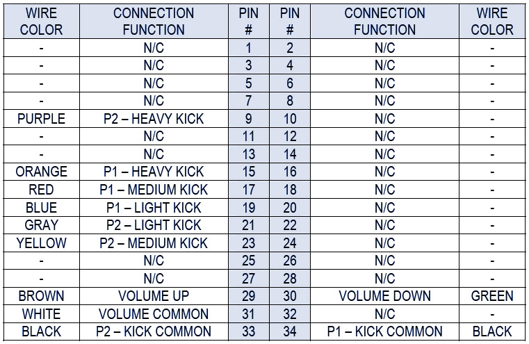
And this is a chart showing the corresponding pinouts on a Capcom game
Image

So I did the continuity check as you said. Checking p1-4 and p1-5 on the screw terminals show their respective pins on the p1 controller port. However, checking p1-6 shows it goes to pin 1. This is ground pin actually. In fact the terminals B6/GND and GND go to the same pin, pin 1. Pin 1 is needed for ground, which leaves nothing for kick 3. By the way I tried linking pin 1 to kick 3 and it didn't work. I don't know why the makers of the supergun didn't give p1-6 it's own pin as there is plenty that are unused. What I did was, as you can see in this picture was to use a wire and link it to pin 10 on the controller port and connect p1-6 from the kick harness to it. This is so I can disconnect the kick harness. I used hot glue by the way and I don't recommend it unless you want it to be permanent, because removing it leaves residues.
Image

So the unsolved mystery is how can I get p1-6 to work (other than what I did) if the B6/GND terminal goes to one and the same ground pin. Was a this design mistake, which I doubt it or am I missing something (I wouldn't be surprise because my knowledge is quite limited). So the question is why is the kick 3 button and ground go to the same pin?
User avatar
CkRtech
Posts: 668
Joined: Mon Aug 27, 2012 9:30 pm
Location: Seattle, WA

Re: Not getting power on Kick 3 on CPS2

Post by CkRtech »

OK. You have an area on your board called OPT1 which might be used as an optional solder point for choosing between using the JAMMA harness pin 27 (which is GND, btw) or not. The rough French to English translation of the page states (for OPT1)
It connects pin 27 of the Jamma connector with a solder bridge:

Either the mass JAMMA standard, which is not done by default.
Either pin # 9 of Sub-D15 connector first player to connect a 6th button

This is to support cards JAMMA "exotic" as some XXX in 1
It...doesn't quite translate right, I think. But basically - I think you are currently pushing JAMMA pin 27 (which is GND) to the P1-6 screw terminal, and you need to disable that. I can't tell if there is a solder bridge there (to bridge 27 to your P1-6 terminal), but there shouldn't be. The reason they do that is because some "50 in 1" JAMMA boards or whathaveyou basically use those "unused" JAMMA pins.

I am surprised they didn't send you some sort of documentation for this board...in fact, my own research on this board has been rather disappointing. The English document on their website needs some serious work. Any solder points should be documented properly no matter what language.
retrogamingjohnny
Posts: 60
Joined: Thu May 15, 2014 4:35 am
Location: United States

Re: Not getting power on Kick 3 on CPS2

Post by retrogamingjohnny »

CkRtech wrote:OK. You have an area on your board called OPT1 which might be used as an optional solder point for choosing between using the JAMMA harness pin 27 (which is GND, btw) or not. The rough French to English translation of the page states (for OPT1)
It connects pin 27 of the Jamma connector with a solder bridge:

Either the mass JAMMA standard, which is not done by default.
Either pin # 9 of Sub-D15 connector first player to connect a 6th button

This is to support cards JAMMA "exotic" as some XXX in 1
It...doesn't quite translate right, I think. But basically - I think you are currently pushing JAMMA pin 27 (which is GND) to the P1-6 screw terminal, and you need to disable that. I can't tell if there is a solder bridge there (to bridge 27 to your P1-6 terminal), but there shouldn't be. The reason they do that is because some "50 in 1" JAMMA boards or whathaveyou basically use those "unused" JAMMA pins.

I am surprised they didn't send you some sort of documentation for this board...in fact, my own research on this board has been rather disappointing. The English document on their website needs some serious work. Any solder points should be documented properly no matter what language.
I was thinking about contacting the website for instructions, but they never answered my first inquiry about power supply so that wasn't a choice. This is getting complicated to me. I found this article, again has to be translated, but basically this dude was able to add an 8 button stick to the supergun. He did a lot of work into it. I didn't read the whole thing, but I think some might find it useful http://www.smallcab.net/stick-arcade-po ... anguage=en
User avatar
CkRtech
Posts: 668
Joined: Mon Aug 27, 2012 9:30 pm
Location: Seattle, WA

Re: Not getting power on Kick 3 on CPS2

Post by CkRtech »

Yeah. Looks like he bridged that opt1 (and opt2) to get button six. Check continuity on those points. Probably solder bridge the same place he did. That should get your button issue solved.
retrogamingjohnny
Posts: 60
Joined: Thu May 15, 2014 4:35 am
Location: United States

Re: Not getting power on Kick 3 on CPS2

Post by retrogamingjohnny »

CkRtech wrote:Yeah. Looks like he bridged that opt1 (and opt2) to get button six. Check continuity on those points. Probably solder bridge the same place he did. That should get your button issue solved.
I bridged the opt1 solder points as marked in the tutorial picture by placing solder between the first and middle blocks. After doing that, there is continuity between the B6/GND terminal and pin 9 of the sub-db15 connector. I thought it should work at this point. I tested a capcom game, and button 6 didn't do anything. I went to the service menu and checked the buttons. The screen shows button 6 on all the time. That explains why it is not working. It's on all the time. This is the same result as before I bridged those blocks on the opt1. I tried every possibility, merging the two on the right, or merging all three, but still can't get it to work.

As for continuity, this is how it goes:
On the OPT1 blocks, the one on the left goes to pin 9 of the sub-db15 connector, the one on the middle goes to B6/GND on the screw terminals, and the third goes to pin 1,2,A and B of the jamma connector.

It's not really a big deal. I can just use it the way I am doing now. It's just an unsolved mystery and I can't seem to get button 6 to work by connecting to the B6/GND screw terminal at this point.
User avatar
CkRtech
Posts: 668
Joined: Mon Aug 27, 2012 9:30 pm
Location: Seattle, WA

Re: Not getting power on Kick 3 on CPS2

Post by CkRtech »

retrogamingjohnny wrote:The screen shows button 6 on all the time.
Yeah. It was already connected to ground, so you would need a way to "un-ground" it. There wasn't already solder bridging pins 2 to 3 were there? If they were going to do this, I don't understand why they didn't have at least a jumper so you can switch between bridging 1 and 2 and 2 and 3. A switch would have been even better.

My assumption is that 1 leads to your terminal, 2 is the common "bridge" pin that leads to your DB-15 port, and 3 is the ground pin to JAMMA 27. It seems like 2 and 3 would have been bridged by default in order for you to have ground showing up for button 6 in your db-15 port. And as it is right now, it seems like 1, 2 and 3 are bridged.

(I basically named the solder points so that 1 was above the "O," 2 was above the "P," and 3 was above the "T.")

If you are happy with your current solution, I suppose it doesn't matter.
retrogamingjohnny
Posts: 60
Joined: Thu May 15, 2014 4:35 am
Location: United States

Re: Not getting power on Kick 3 on CPS2

Post by retrogamingjohnny »

CkRtech wrote:
retrogamingjohnny wrote:The screen shows button 6 on all the time.
Yeah. It was already connected to ground, so you would need a way to "un-ground" it. There wasn't already solder bridging pins 2 to 3 were there? If they were going to do this, I don't understand why they didn't have at least a jumper so you can switch between bridging 1 and 2 and 2 and 3. A switch would have been even better.

My assumption is that 1 leads to your terminal, 2 is the common "bridge" pin that leads to your DB-15 port, and 3 is the ground pin to JAMMA 27. It seems like 2 and 3 would have been bridged by default in order for you to have ground showing up for button 6 in your db-15 port. And as it is right now, it seems like 1, 2 and 3 are bridged.

(I basically named the solder points so that 1 was above the "O," 2 was above the "P," and 3 was above the "T.")

If you are happy with your current solution, I suppose it doesn't matter.
It would nice to know how to un-ground it.
There wasn't already solder bridging pins 2 to 3 were there?
No. They weren't bridged when I got it.

I am not really happy with it. It would be nice if I could use the B6/GND terminal for button 6 as it seems to be designed for that. But I can live with it since I can still get button 6 to work somehow and I spent a lot of time in it already. Thanks for your help. I learned a lot from you during this troubleshooting.
Post Reply