Sync Amplifier
-
EmperorZelos
- Posts: 265
- Joined: Fri Jul 19, 2013 3:39 pm
Sync Amplifier
Does anyone know where I could get a sync signal amplifier for scart or make into capable for scarts?
-
EmperorZelos
- Posts: 265
- Joined: Fri Jul 19, 2013 3:39 pm
Re: Sync Amplifier
Or anyone who'd be willing to make one or how I would make one myself?
-
EmperorZelos
- Posts: 265
- Joined: Fri Jul 19, 2013 3:39 pm
Re: Sync Amplifier
I'll probably be trying to create my own sync using a THS7314 chip but I have a question
I'll be using an external poewr supply for it, naturally, to amplify it, but I have a question, the power plug has only positive nad negative part to it and I am not familiar enough with the "ground" concept, isthe ground either of them or does the grounding of the chip go to the scart signal I am putting into the device or how would I connect it?
I know it demands a poewr input where the 5V would be put into it and then I get signal out, but the ground part is the issue, do I connect the ground part onward as if it was a serial connection or do I connect it to the scart? Or does the chip get parallel connected with the power supply?
-
airs
- Posts: 198
- Joined: Thu May 02, 2013 6:00 pm
- Location: Seattle, WA
Re: Sync Amplifier
Hey EmperorZelos, what's the problem you're trying to solve? Can you tell us about your setup?
-
EmperorZelos
- Posts: 265
- Joined: Fri Jul 19, 2013 3:39 pm
Re: Sync Amplifier
I have many different consoles that goes through 1 or 2 scart switches, and when it goes through 2, but not 1, the screen flickers due to sync issues but not when directly connected to the first scart switchairs wrote:Hey EmperorZelos, what's the problem you're trying to solve? Can you tell us about your setup?
-
Legion
- Posts: 22
- Joined: Tue Jun 17, 2014 3:10 am
Re: Sync Amplifier
For the THS7314, ground would be connected to negative and 5V to your positive. Ground is a reference point. So when you talk about 5V, 5V above what? Above ground. A good analogy would be the altitude of an airplane. When we say an airplane is at 10 000ft, we need a reference point. Is it 10 000 ft above sea level? 10 000 ft above the surface of the earth? Similarly in electrical circuits we need a reference point, and that's what ground is. When you look at a AA battery, the positive end is 1.5V ABOVE the negative end. The negative end is your ground.EmperorZelos wrote:I'll probably be trying to create my own sync using a THS7314 chip but I have a question
I'll be using an external poewr supply for it, naturally, to amplify it, but I have a question, the power plug has only positive nad negative part to it and I am not familiar enough with the "ground" concept, isthe ground either of them or does the grounding of the chip go to the scart signal I am putting into the device or how would I connect it?
I know it demands a poewr input where the 5V would be put into it and then I get signal out, but the ground part is the issue, do I connect the ground part onward as if it was a serial connection or do I connect it to the scart? Or does the chip get parallel connected with the power supply?
-
Legion
- Posts: 22
- Joined: Tue Jun 17, 2014 3:10 am
Re: Sync Amplifier
I should add that hooking up a THS7314 directly to a 5V DC wall adapter is probably not a good idea. You'll want to add a filter capacitor in between to smooth out the power.
-
airs
- Posts: 198
- Joined: Thu May 02, 2013 6:00 pm
- Location: Seattle, WA
Re: Sync Amplifier
Which scart switch are you using two of? Bandridge unpowered manual? Automatic powered? Another?
-
mickcris

- Posts: 435
- Joined: Tue Oct 08, 2013 12:43 am
- Location: Texas, USA
Re: Sync Amplifier
I had tried chaining 2 bandrige 5 port automatic switches and had the same issue of some consoles not working on the 2nd switch.
-
EmperorZelos
- Posts: 265
- Joined: Fri Jul 19, 2013 3:39 pm
Re: Sync Amplifier
Atleast I am not alonemickcris wrote:I had tried chaining 2 bandrige 5 port automatic switches and had the same issue of some consoles not working on the 2nd switch.
Bandridge automatic as teh guy mentioned.airs wrote:Which scart switch are you using two of? Bandridge unpowered manual? Automatic powered? Another?
Thank you so much that helps so much!Legion wrote: For the THS7314, ground would be connected to negative and 5V to your positive. Ground is a reference point. So when you talk about 5V, 5V above what? Above ground. A good analogy would be the altitude of an airplane. When we say an airplane is at 10 000ft, we need a reference point. Is it 10 000 ft above sea level? 10 000 ft above the surface of the earth? Similarly in electrical circuits we need a reference point, and that's what ground is. When you look at a AA battery, the positive end is 1.5V ABOVE the negative end. The negative end is your ground.
Should it be serial connecting or parallel connecting between the two? My gut says parallel
I was going to go like thisLegion wrote:I should add that hooking up a THS7314 directly to a 5V DC wall adapter is probably not a good idea. You'll want to add a filter capacitor in between to smooth out the power.
http://www.mmmonkey.co.uk/ntsc-nintendo-64-rgb/
Except for of course the sync signal
But the THS chip it makes the signal go up to 5V or does it increase it relatively speaking? So a 4,5V signal in becomes like 9,5V or?
I know, or think I do, that the signal should be 1V and I understand correctly I can, if the amplifier does the work "too well" decrease the voltage with a proper resistor right?
PS:
I have checked the signal between pin 20 (composite in with the sync as I understand) and pin 18 and 17 (both grounds)and I get 1,4V (between 1,41 and 1,45) when I use my consoles going through 1 of the switches and when I use one of the consoles going through both switches I get the same signal strength.
-
EmperorZelos
- Posts: 265
- Joined: Fri Jul 19, 2013 3:39 pm
Re: Sync Amplifier
Did you figure out the cause of this?mickcris wrote:I had tried chaining 2 bandrige 5 port automatic switches and had the same issue of some consoles not working on the 2nd switch.
-
Asure
- Posts: 42
- Joined: Sun May 04, 2014 3:06 pm
Re: Sync Amplifier
Do these bandridge devices use a power supply? If not, they are running / switching off the 1-4 volts they get from the scart plug which seems unlikely to me, but possible, and most probable cause.
Other than that, it is likely a voltage drop over the switch logic, cables and cables. Even if the bandridge devices are powered.
Normally, you have one scart cable ->TV
Now you have two lengths of cable (switch ->tv and device-> switch) and some logic ic's inside the switch, causing the level of the sync signal to drop.
If there is a second switch daisychained in between, the signal drops even further over the second lenght of cable and that's why the devices on the second switch fail to work properly.
Maybe you can move some of the 'properly' working devices to the closest switch, trail and error.. Not all devices have the same output levels. Some are a bit higher
If that's not possible, you would need to amplify the signals on all of the non-working devices, not just the sync.
-
EmperorZelos
- Posts: 265
- Joined: Fri Jul 19, 2013 3:39 pm
Re: Sync Amplifier
They have their own power supplyAsure wrote:Do these bandridge devices use a power supply? If not, they are running / switching off the 1-4 volts they get from the scart plug which seems unlikely to me, but possible, and most probable cause.
Other than that, it is likely a voltage drop over the switch logic, cables and cables. Even if the bandridge devices are powered.
Normally, you have one scart cable ->TV
Now you have two lengths of cable (switch ->tv and device-> switch) and some logic ic's inside the switch, causing the level of the sync signal to drop.
If there is a second switch daisychained in between, the signal drops even further over the second lenght of cable and that's why the devices on the second switch fail to work properly.
Maybe you can move some of the 'properly' working devices to the closest switch, trail and error.. Not all devices have the same output levels. Some are a bit higher
If that's not possible, you would need to amplify the signals on all of the non-working devices, not just the sync.
So amplifier would help it? I could easily make the amplifier for all (I have ordered parts for it all already and I can amplify all signals if needed) I just need help with getting the right levels with the circuit and such and I can do the stuff on my own I think. To me it sounds like a good idea having an amplifier after the last switch that gets the signal right and then let it move on.
I suspected the sync one early on (as the framemeister is very sensitive to it's levels) through trial and error it is the must likely culprit, I did measure the signal from gamecube (directly) through the first switch adn then second switch daisychained and they all lied above 1,4V if I measured it correctly
-
Asure
- Posts: 42
- Joined: Sun May 04, 2014 3:06 pm
Re: Sync Amplifier
Grab the multimeter, set it to ohms, and measure the resistance from point A to point B.
Point A being the input port's SYNC pin on the scart connector, point B being the SYNC pin on the scart cable you would plug into the second bandridge box.
In this case, pin 20 on both sides. Post the value here for us to check. You may want to switch the bandrige to that port.
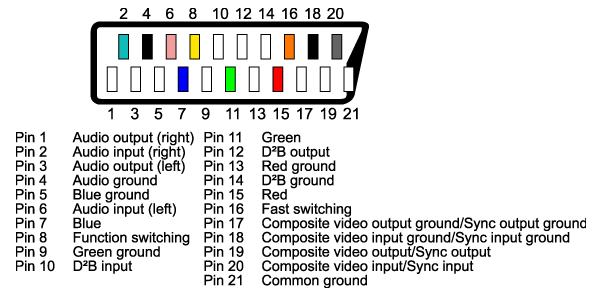
The voltage you're measuring is just a momentary voltage, a single snapshot. (The actual Sync line has several pulses and should pulse low, but this cannot be detected by a simple multimeter, it just measures volts and cannot detect the 'low' pulses. You'll need a multimeter to confirm what i said, it's a voltage drop, or perhaps interference...)
To rule out one thing, we need to know the resistance of the wiring and stuff in the bandrige..
Point A being the input port's SYNC pin on the scart connector, point B being the SYNC pin on the scart cable you would plug into the second bandridge box.
In this case, pin 20 on both sides. Post the value here for us to check. You may want to switch the bandrige to that port.
The voltage you're measuring is just a momentary voltage, a single snapshot. (The actual Sync line has several pulses and should pulse low, but this cannot be detected by a simple multimeter, it just measures volts and cannot detect the 'low' pulses. You'll need a multimeter to confirm what i said, it's a voltage drop, or perhaps interference...)
To rule out one thing, we need to know the resistance of the wiring and stuff in the bandrige..
-
Legion
- Posts: 22
- Joined: Tue Jun 17, 2014 3:10 am
Re: Sync Amplifier
I'm not sure what you mean by connecting in serial or parallel. The amp should be in series with the signal chain.EmperorZelos wrote:Should it be serial connecting or parallel connecting between the two? My gut says parallel.
I was going to go like this
http://www.mmmonkey.co.uk/ntsc-nintendo-64-rgb/
Except for of course the sync signal
In your third post you talked about using an external power supply. But the N64 mod you linked do doesn't use an external supply, it takes 5V and ground off of the N64's circuit board. In that case your amp will only amplify the signal of the console you put it in. It won't help any other consoles running through your switches. If you want to do that, then you won't need any filter caps other than the one shown in the link between 5V and ground. If you're trying to make an amp that will sit between the last switch and the TV, then you'll need to provide power and your own filtering.
-
mickcris
- Posts: 435
- Joined: Tue Oct 08, 2013 12:43 am
- Location: Texas, USA
Re: Sync Amplifier
No. I just gave up on hooking them up that way.EmperorZelos wrote:Did you figure out the cause of this?mickcris wrote:I had tried chaining 2 bandrige 5 port automatic switches and had the same issue of some consoles not working on the 2nd switch.
-
EmperorZelos
- Posts: 265
- Joined: Fri Jul 19, 2013 3:39 pm
Re: Sync Amplifier
So I should measure the resistence of the scart switch over pin 20? Just so I understand perfectlyAsure wrote:Grab the multimeter, set it to ohms, and measure the resistance from point A to point B.
Point A being the input port's SYNC pin on the scart connector, point B being the SYNC pin on the scart cable you would plug into the second bandridge box.
In this case, pin 20 on both sides. Post the value here for us to check. You may want to switch the bandrige to that port.
The voltage you're measuring is just a momentary voltage, a single snapshot. (The actual Sync line has several pulses and should pulse low, but this cannot be detected by a simple multimeter, it just measures volts and cannot detect the 'low' pulses. You'll need a multimeter to confirm what i said, it's a voltage drop, or perhaps interference...)
To rule out one thing, we need to know the resistance of the wiring and stuff in the bandrige..
I am not entirely certain how to do it either considering it automaticly switches and it wouldn't be getting any current through it to switch to and without a signal it doesn't tell if it is switched or not to the right port, but guide me through it and I shall do it!
PS: I have tried measuring the pins on the Bandridge box, I first tried the contiunuity setting to see if it went through, I had it powered and selected input 1, but there is no continuity in any of the pins, except between all the ground pins, so I don't know how to measure them
PSS: I was dumb enough to measure over hte wrong pins, I realised pin 20 in is pin 19 out and tried it again getting contuinity and readings of the resistence, If I read it right, on 20k ohm setting, i get 5 or 14 so it oughta be 5k or 14k ohm resistence if I have done it right. I also measured the grounded pin 21 which has close to 0 in resistence. Sometimes I seem to get 5k and others 14k resistence, not quite sure why it shifts
PSSS: I have checked the other ports, sound, RGB etc, they all measure the same resistence.
oh I meant I get 5V of power from an external power source that I utilize to amplify the signal and the question is if the amplifier should be serial or parallel with the electricity comming from the external power source (in this case it is the poewr to the framemeister), I would use that merely as a guide to connect things in and out with the stuff which oughta work wether it is in there or not as they both get 5VLegion wrote: I'm not sure what you mean by connecting in serial or parallel. The amp should be in series with the signal chain.
In your third post you talked about using an external power supply. But the N64 mod you linked do doesn't use an external supply, it takes 5V and ground off of the N64's circuit board. In that case your amp will only amplify the signal of the console you put it in. It won't help any other consoles running through your switches. If you want to do that, then you won't need any filter caps other than the one shown in the link between 5V and ground. If you're trying to make an amp that will sit between the last switch and the TV, then you'll need to provide power and your own filtering.
-
EmperorZelos
- Posts: 265
- Joined: Fri Jul 19, 2013 3:39 pm
Re: Sync Amplifier
Did that provide the neccisery information? I think that might be the culprit then
-
Asure
- Posts: 42
- Joined: Sun May 04, 2014 3:06 pm
Re: Sync Amplifier
I forgot those things are auto switching and it's impossible to measure the resistance the way i had in mind. Those values you get are not usefull.
But, since they autoswitch, you can deduct there is logic inside, that expects certain levels, and this is exactly what causes the voltage drop.
In this case it's better to just give up using them daisy chained, as that is not what they were designed for.
But, since they autoswitch, you can deduct there is logic inside, that expects certain levels, and this is exactly what causes the voltage drop.
In this case it's better to just give up using them daisy chained, as that is not what they were designed for.
-
EmperorZelos
- Posts: 265
- Joined: Fri Jul 19, 2013 3:39 pm
Re: Sync Amplifier
If there is a voltage drop, wouldn't amplifying the signal solve hte issue?Asure wrote:I forgot those things are auto switching and it's impossible to measure the resistance the way i had in mind. Those values you get are not usefull.
But, since they autoswitch, you can deduct there is logic inside, that expects certain levels, and this is exactly what causes the voltage drop.
In this case it's better to just give up using them daisy chained, as that is not what they were designed for.
-
airs
- Posts: 198
- Joined: Thu May 02, 2013 6:00 pm
- Location: Seattle, WA
Re: Sync Amplifier
Perhaps it has to do with the 5th port like on the manual one?

Thread: http://shmups.system11.org/viewtopic.php?f=6&t=48460
Thread: http://shmups.system11.org/viewtopic.php?f=6&t=48460
-
EmperorZelos
- Posts: 265
- Joined: Fri Jul 19, 2013 3:39 pm
Re: Sync Amplifier
I acctually treid opening it but couldn't even with the screws out. Not sure how to open itairs wrote:Perhaps it has to do with the 5th port like on the manual one?
Thread: http://shmups.system11.org/viewtopic.php?f=6&t=48460
-
EmperorZelos
- Posts: 265
- Joined: Fri Jul 19, 2013 3:39 pm
Re: Sync Amplifier
I am going to try the amplifier thing to see if it does help, I have to use parallel connection on it when connecting the power cable also to the framemesiter to ensure both get 5V right?