Just checked and the micon is 5.0VRyeno wrote:InfamousSabre wrote:
I'm getting started on that right now. The micon is socketed so I'd hoped to just unsocket it, bend up the 3 output pins, then resocket, but its stuck in there pretty tight and theres a metal shield all around it so I cant slip a screwdriver underneath to pry it up like usual. Going to just desolder that first resistor (3310, 3318, 3320) to disconnect the micon from the rest of that circuit. Then, on the jungle side, that 1uf capacitor is through-hole so ill pull up the micon-facing leg, removing the jungle from the circuit. After that I can get wires running out to a breadboard and look at creating the mux circuit like you said.
At the micon, on the RED-OSD, GRN-OSD, and BLU-OSD pins, it says 0V. If there's 0 volts coming out of those pins, how on earth does it work? Or am I just reading it improperly?
Easiest way to RGB mod is to use as 4PDT Switch at the 1uF input caps. This method will work 100% but you'll lose OSD in RGB mod.
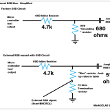
The other option is to remove 120 ohm grounding resistors and replace them with 75 ohm and 39 ohm and inject RGB between the 2 resistors. Is the Micon 5V or 7.5V?
TV RGB mod thread
-
InfamousSabre
- Posts: 13
- Joined: Fri Jul 22, 2016 1:57 pm
Re: TV RGB mod thread
Re: TV RGB mod thread
Ok, I'll try again.InfamousSabre wrote:Alright I'm back again with yet another set. This is a GE 20GH250 with a CTC-176K2 chassis utilizing a Sanyo LA7610 jungle chip.
The schematic for this TV looks really odd to me though. I cant quite understand where I should inject RGB. Can anyone help me out here?

If it's a 5V micom that is sending OSD high pulses...
Using the green circuit as an example.
I would remove R3317, R2712 and Q2701. I would short between the holes left by the base and collector of Q2701. This should leave us muxing with 1100 ohm factory in-lines. Then I run my 75 ohm terminated external G into a 110 ohm mux resistor and connect it somewhere betwen R2713 and C2707...Perhaps I would connect to the place where I shorted the transistor holes or possibly a twist method 110R and 75R, 75R has leg into emitter hole of Q2701, 110R has leg in Collector hole.
Last edited by MarkOZLAD on Sat Jul 02, 2022 3:16 pm, edited 1 time in total.
___________________________________________________
MarkOZLAD
OSD/External RGB Mux Diagram
OSD/External RGB Mux Resistor Value Table 0.7Vp-p : 0.5Vp-p
"Imagine toggle switch OSD modding a TV in 2019" - maxtherabbit
MarkOZLAD
OSD/External RGB Mux Diagram
OSD/External RGB Mux Resistor Value Table 0.7Vp-p : 0.5Vp-p
"Imagine toggle switch OSD modding a TV in 2019" - maxtherabbit
-
maxtherabbit

- Posts: 1763
- Joined: Mon Mar 05, 2018 4:03 pm
Re: TV RGB mod thread
0V is the nominal voltage on the pin i.e. when the OSD is not active
Re: TV RGB mod thread
I made a typo on my post. I meant 5V micom.maxtherabbit wrote:0V is the nominal voltage on the pin i.e. when the OSD is not active
Assuming micom is sending 5V when OSD is on, 0V when off.
___________________________________________________
MarkOZLAD
OSD/External RGB Mux Diagram
OSD/External RGB Mux Resistor Value Table 0.7Vp-p : 0.5Vp-p
"Imagine toggle switch OSD modding a TV in 2019" - maxtherabbit
MarkOZLAD
OSD/External RGB Mux Diagram
OSD/External RGB Mux Resistor Value Table 0.7Vp-p : 0.5Vp-p
"Imagine toggle switch OSD modding a TV in 2019" - maxtherabbit
Re: TV RGB mod thread
MarkOZLAD wrote:Ok, I'll try again.InfamousSabre wrote:Alright I'm back again with yet another set. This is a GE 20GH250 with a CTC-176K2 chassis utilizing a Sanyo LA7610 jungle chip.
The schematic for this TV looks really odd to me though. I cant quite understand where I should inject RGB. Can anyone help me out here?
If it's a 5V micom that is sending OSD high pulses...
Using the green circuit as an example.
I would remove R3317, R2712 and Q2701. I would short between the holes left by the base and collector of Q2701. This should leave us muxing with 1100 ohm factory in-lines. Then I run my 75 ohm terminated external G into a 110 ohm mux resistor and connect it somewhere betwen R2713 and C2707...Perhaps I would connect to the place where I shorted the transistor holes or possibly a twist method 110R and 75R, 75R has leg into emitter hole of Q2701, 110R has leg in Collector hole.
There is a good chance the MICON can't directly drive the OSD which is why the engineers put the transistors between it and the jungle chip. It's not likely that the engineers simply over-engineered this set. For this reason it makes more sense to simply mux into the base of the transistor and if that doesn't work then use a 4PDT switch without mux.
https://imgur.com/ZvZXpt5
Green is Micon, Blue is output to Jungle.
Re: TV RGB mod thread
Fair call.
I’d like to see if there are any other schematics around that show the same chips in use.
I’d like to see if there are any other schematics around that show the same chips in use.
___________________________________________________
MarkOZLAD
OSD/External RGB Mux Diagram
OSD/External RGB Mux Resistor Value Table 0.7Vp-p : 0.5Vp-p
"Imagine toggle switch OSD modding a TV in 2019" - maxtherabbit
MarkOZLAD
OSD/External RGB Mux Diagram
OSD/External RGB Mux Resistor Value Table 0.7Vp-p : 0.5Vp-p
"Imagine toggle switch OSD modding a TV in 2019" - maxtherabbit
-
InfamousSabre
- Posts: 13
- Joined: Fri Jul 22, 2016 1:57 pm
Re: TV RGB mod thread
So, using Green as an example, this is all I need to do for the RGB lines?Ryeno wrote:InfamousSabre wrote:
I'm getting started on that right now. The micon is socketed so I'd hoped to just unsocket it, bend up the 3 output pins, then resocket, but its stuck in there pretty tight and theres a metal shield all around it so I cant slip a screwdriver underneath to pry it up like usual. Going to just desolder that first resistor (3310, 3318, 3320) to disconnect the micon from the rest of that circuit. Then, on the jungle side, that 1uf capacitor is through-hole so ill pull up the micon-facing leg, removing the jungle from the circuit. After that I can get wires running out to a breadboard and look at creating the mux circuit like you said.
At the micon, on the RED-OSD, GRN-OSD, and BLU-OSD pins, it says 0V. If there's 0 volts coming out of those pins, how on earth does it work? Or am I just reading it improperly?
Easiest way to RGB mod is to use as 4PDT Switch at the 1uF input caps. This method will work 100% but you'll lose OSD in RGB mod.
The other option is to remove 120 ohm grounding resistors and replace them with 75 ohm and 43 ohm and inject RGB between the 2 resistors. Is the Micon 5V or 7.5V?

Last edited by InfamousSabre on Sat May 11, 2024 8:59 pm, edited 1 time in total.
Re: TV RGB mod thread
So you think the transistor will linearly amplify the external RGB? Very cool if it does.InfamousSabre wrote:So, using Green as an example, this is all I need to do for the RGB lines?Ryeno wrote:InfamousSabre wrote:
I'm getting started on that right now. The micon is socketed so I'd hoped to just unsocket it, bend up the 3 output pins, then resocket, but its stuck in there pretty tight and theres a metal shield all around it so I cant slip a screwdriver underneath to pry it up like usual. Going to just desolder that first resistor (3310, 3318, 3320) to disconnect the micon from the rest of that circuit. Then, on the jungle side, that 1uf capacitor is through-hole so ill pull up the micon-facing leg, removing the jungle from the circuit. After that I can get wires running out to a breadboard and look at creating the mux circuit like you said.
At the micon, on the RED-OSD, GRN-OSD, and BLU-OSD pins, it says 0V. If there's 0 volts coming out of those pins, how on earth does it work? Or am I just reading it improperly?
Easiest way to RGB mod is to use as 4PDT Switch at the 1uF input caps. This method will work 100% but you'll lose OSD in RGB mod.
The other option is to remove 120 ohm grounding resistors and replace them with 75 ohm and 43 ohm and inject RGB between the 2 resistors. Is the Micon 5V or 7.5V?

___________________________________________________
MarkOZLAD
OSD/External RGB Mux Diagram
OSD/External RGB Mux Resistor Value Table 0.7Vp-p : 0.5Vp-p
"Imagine toggle switch OSD modding a TV in 2019" - maxtherabbit
MarkOZLAD
OSD/External RGB Mux Diagram
OSD/External RGB Mux Resistor Value Table 0.7Vp-p : 0.5Vp-p
"Imagine toggle switch OSD modding a TV in 2019" - maxtherabbit
Re: TV RGB mod thread
That should work as long as the MICON resistor is 1k and not 3k and it isn't doing anything weird like grounding the output when not in use.InfamousSabre wrote:So, using Green as an example, this is all I need to do for the RGB lines?Ryeno wrote:InfamousSabre wrote:
I'm getting started on that right now. The micon is socketed so I'd hoped to just unsocket it, bend up the 3 output pins, then resocket, but its stuck in there pretty tight and theres a metal shield all around it so I cant slip a screwdriver underneath to pry it up like usual. Going to just desolder that first resistor (3310, 3318, 3320) to disconnect the micon from the rest of that circuit. Then, on the jungle side, that 1uf capacitor is through-hole so ill pull up the micon-facing leg, removing the jungle from the circuit. After that I can get wires running out to a breadboard and look at creating the mux circuit like you said.
At the micon, on the RED-OSD, GRN-OSD, and BLU-OSD pins, it says 0V. If there's 0 volts coming out of those pins, how on earth does it work? Or am I just reading it improperly?
Easiest way to RGB mod is to use as 4PDT Switch at the 1uF input caps. This method will work 100% but you'll lose OSD in RGB mod.
The other option is to remove 120 ohm grounding resistors and replace them with 75 ohm and 43 ohm and inject RGB between the 2 resistors. Is the Micon 5V or 7.5V?
If it works, you could also increase the filter capacitor from 22pF to 10nF. That would decrease interferance.
Re: TV RGB mod thread
Ok new attemp, this time a disney mikey mouse tv dt1350-c model, should be an easy mod, but because its a componets on the board type, and not the holes type, ill have to pay someone to solder some cables for me. Anyway, i saw the segaholic performing a mod but it looks to complicated with the switch and stuff, and with the new example (new for me) i saw from markozlad, i think i understud how to perform this. So heres a mockup o my model
The new example tells me where to inject the rgb signal, but i still need to understand, how do i keep the 5v from going to the micon, so it wont fry it over time? do we still use a switch for that or am i missing something? im gonna go read the whole topci againg to find out. But if anyone cares to answer ill apreciate it.
Now i need to photoshop the cables at my service manul picture so i know where to solder the cables.
Ill keep this updated, thanks
-
KPackratt2k
- Posts: 220
- Joined: Sun Apr 04, 2021 11:02 pm
- Location: Seattle, WA, USA
Re: TV RGB mod thread
Here's my modding schematic for this chassis based on MarkOZLAD's recommendations:abispac wrote:Ok new attemp, this time a disney mikey mouse tv dt1350-c model, should be an easy mod, but because its a componets on the board type, and not the holes type, ill have to pay someone to solder some cables for me. Anyway, i saw the segaholic performing a mod but it looks to complicated with the switch and stuff, and with the new example (new for me) i saw from markozlad, i think i understud how to perform this. So heres a mockup o my model
https://klovimg.com/image/CqEXp
The new example tells me where to inject the rgb signal, but i still need to understand, how do i keep the 5v from going to the micon, so it wont fry it over time? do we still use a switch for that or am i missing something? im gonna go read the whole topci againg to find out. But if anyone cares to answer ill apreciate it.
Now i need to photoshop the cables at my service manul picture so i know where to solder the cables.
Ill keep this updated, thanks

Even if you're using SCART, I would still recommend using a switch for blanking because not all cables handle blanking. If you insist on blanking via SCART, you can try adding a diode on the blanking wire.
If you have more than one of these TVs and wouldn't mind parting one of them out for me, let me know. I have a Mickey TV that suffered from a vertical IC failure and I wasn't able to fix its chassis. I would love to get mine working again.
Re: TV RGB mod thread
Why did you use 750 instead of 510 as sugested in the Markozlad guide? And let me see if can get one chassis for you, this tvs are common on my city, i live at the border with texas and today i got this one for 10dlls, i have bought some in the past but they where diferent inside. Still the same mod could have been perfomed.KPackratt2k wrote:Here's my modding schematic for this chassis based on MarkOZLAD's recommendations:abispac wrote:Ok new attemp, this time a disney mikey mouse tv dt1350-c model, should be an easy mod, but because its a componets on the board type, and not the holes type, ill have to pay someone to solder some cables for me. Anyway, i saw the segaholic performing a mod but it looks to complicated with the switch and stuff, and with the new example (new for me) i saw from markozlad, i think i understud how to perform this. So heres a mockup o my model
https://klovimg.com/image/CqEXp
The new example tells me where to inject the rgb signal, but i still need to understand, how do i keep the 5v from going to the micon, so it wont fry it over time? do we still use a switch for that or am i missing something? im gonna go read the whole topci againg to find out. But if anyone cares to answer ill apreciate it.
Now i need to photoshop the cables at my service manul picture so i know where to solder the cables.
Ill keep this updated, thanks
Even if you're using SCART, I would still recommend using a switch for blanking because not all cables handle blanking. If you insist on blanking via SCART, you can try adding a diode on the blanking wire.
If you have more than one of these TVs and wouldn't mind parting one of them out for me, let me know. I have a Mickey TV that suffered from a vertical IC failure and I wasn't able to fix its chassis. I would love to get mine working again.
Re: TV RGB mod thread
I'm not sure what I put in the guide but if the OSD inlines are 4700 Ohm my lookup table for 0.7V no diodes says 750 Ohm mux.abispac wrote: Why did you use 750 instead of 510 as sugested in the Markozlad guide? And let me see if can get one chassis for you, this tvs are common on my city, i live at the border with texas and today i got this one for 10dlls, i have bought some in the past but they where diferent inside. Still the same mod could have been perfomed.
___________________________________________________
MarkOZLAD
OSD/External RGB Mux Diagram
OSD/External RGB Mux Resistor Value Table 0.7Vp-p : 0.5Vp-p
"Imagine toggle switch OSD modding a TV in 2019" - maxtherabbit
MarkOZLAD
OSD/External RGB Mux Diagram
OSD/External RGB Mux Resistor Value Table 0.7Vp-p : 0.5Vp-p
"Imagine toggle switch OSD modding a TV in 2019" - maxtherabbit
-
thchardcore
- Posts: 484
- Joined: Wed Jun 22, 2005 9:20 am
- Location: Liberal cesspool
Re: TV RGB mod thread
Just curious, but why are the Disney TVs so popular? Seems like everyone wants one.
A camel is a horse designed by a committee
-
maxtherabbit
- Posts: 1763
- Joined: Mon Mar 05, 2018 4:03 pm
Re: TV RGB mod thread
meme tvthchardcore wrote:Just curious, but why are the Disney TVs so popular? Seems like everyone wants one.
Re: TV RGB mod thread
Arent we using 5v instead of 7v? if is 5v then the guiide says to use 510ohms insteadMarkOZLAD wrote:I'm not sure what I put in the guide but if the OSD inlines are 4700 Ohm my lookup table for 0.7V no diodes says 750 Ohm mux.abispac wrote: Why did you use 750 instead of 510 as sugested in the Markozlad guide? And let me see if can get one chassis for you, this tvs are common on my city, i live at the border with texas and today i got this one for 10dlls, i have bought some in the past but they where diferent inside. Still the same mod could have been perfomed.
Thats another thing i still dont understand, is o.5 = to 5v and 0.7 =7v? or does it mean something else?
The segaholic guy , uses 5v , so i though using the 510 ohms whats the correct way. but if Markozlad told you to use 750, then i guess ill use 750 ones.
Last edited by abispac on Mon Jul 04, 2022 7:56 pm, edited 1 time in total.
Re: TV RGB mod thread
Well, i got this obsesion to build a couple of small arcades with 13 inch monitors, but real arcade monitors that size are betwen 250 dlls and up, not to ention the chassis are way to old and use and they a pain in the ass, they break real easy and wont last long. tvs on the other side, i find them to have a better shape, no broken solders, the parts last longer as they have not been abused. so im giving this small tvs a better chanse than arcade monitors, plus the picture looks nice. thas my personal opinion.thchardcore wrote:Just curious, but why are the Disney TVs so popular? Seems like everyone wants one.
Re: TV RGB mod thread
I just picked up a Philips 19PS40 and think it's a great candidate for an RGB mod as the composite quality really stunned me when i first turned it on. This will be my first time RGB modding, but i've modded consoles and repaired speakers and CRTs before so i'm not a complete noob.
I've found the relevant service docs and uploaded them to archive.org here: https://archive.org/details/7602_20220703
Starting on page 96 of 7602.pdf we've got the schematics that can help us figure this out before opening it up. I will open it up and take photos of the board later. These docs are for the chassis this uses, but i've got a consumer set so there's a bunch of unused stuff on the board.
My set only has composite on the front (with headphone out) and RF on the back. My primary goal is to add RGB; there isn't much room to add those ports on the front near the existing composite, so adding another composite for sync on the back would be ideal. I'd love to replace the RF with composite and use that for sync. Doing that would also require adding audio jacks on the back as well though.
So I believe this means I need to get myself some BNC jacks and RCA jacks. I've got wire and resistors and soldering tools already. Anything else i'm missing before i crack this open and photograph the board?
Re: TV RGB mod thread
PressLeft wrote:I just picked up a Philips 19PS40 and think it's a great candidate for an RGB mod as the composite quality really stunned me when i first turned it on. This will be my first time RGB modding, but i've modded consoles and repaired speakers and CRTs before so i'm not a complete noob.
I've found the relevant service docs and uploaded them to archive.org here: https://archive.org/details/7602_20220703
Starting on page 96 of 7602.pdf we've got the schematics that can help us figure this out before opening it up. I will open it up and take photos of the board later. These docs are for the chassis this uses, but i've got a consumer set so there's a bunch of unused stuff on the board.
My set only has composite on the front (with headphone out) and RF on the back. My primary goal is to add RGB; there isn't much room to add those ports on the front near the existing composite, so adding another composite for sync on the back would be ideal. I'd love to replace the RF with composite and use that for sync. Doing that would also require adding audio jacks on the back as well though.
So I believe this means I need to get myself some BNC jacks and RCA jacks. I've got wire and resistors and soldering tools already. Anything else i'm missing before i crack this open and photograph the board?
https://pdf1.alldatasheet.com/datasheet ... A955X.html
It appears this jungle chips takes both YUV and RGB through the same pins. I'm not sure how it selects between the 2, might be a firmware setting.
Re: TV RGB mod thread
any way for me to do some probing to find out?Ryeno wrote: It appears this jungle chips takes both YUV and RGB through the same pins. I'm not sure how it selects between the 2, might be a firmware setting.
Re: TV RGB mod thread
actually, according the service manual:PressLeft wrote:any way for me to do some probing to find out?Ryeno wrote: It appears this jungle chips takes both YUV and RGB through the same pins. I'm not sure how it selects between the 2, might be a firmware setting.
"The output of the YUV separator is fed to the internal YUV switch, which switches between the output of the YUV separator or the external YUV (for DVD or PIP) on pins 51-53. Pin 50 is the input for the insertion control signal called 'FBL-1'. When this signal level becomes higher than 0.9 V (but less than 3 V), the RGB signals at pins 51, 52 and 53 are inserted into the picture by using the internal switches"
Re: TV RGB mod thread
These jungle chips can process both signals, but on US models the RGB is locked out in firmware.Ryeno wrote:PressLeft wrote:I just picked up a Philips 19PS40 and think it's a great candidate for an RGB mod as the composite quality really stunned me when i first turned it on. This will be my first time RGB modding, but i've modded consoles and repaired speakers and CRTs before so i'm not a complete noob.
I've found the relevant service docs and uploaded them to archive.org here: https://archive.org/details/7602_20220703
Starting on page 96 of 7602.pdf we've got the schematics that can help us figure this out before opening it up. I will open it up and take photos of the board later. These docs are for the chassis this uses, but i've got a consumer set so there's a bunch of unused stuff on the board.
My set only has composite on the front (with headphone out) and RF on the back. My primary goal is to add RGB; there isn't much room to add those ports on the front near the existing composite, so adding another composite for sync on the back would be ideal. I'd love to replace the RF with composite and use that for sync. Doing that would also require adding audio jacks on the back as well though.
So I believe this means I need to get myself some BNC jacks and RCA jacks. I've got wire and resistors and soldering tools already. Anything else i'm missing before i crack this open and photograph the board?
https://pdf1.alldatasheet.com/datasheet ... A955X.html
It appears this jungle chips takes both YUV and RGB through the same pins. I'm not sure how it selects between the 2, might be a firmware setting.
Many of these can be modded to accept component video, though, and the quality is very good. I made a writeup of how to do it on a similar TV. The process on the TDA955X jungle chips basically the same, although the pinout is different:
https://crtdatabase.com/crts/magnavox/m ... 4ms2331-17
However, one complication is that some of these TVs don't have a service menu. For those models, you have to use an obtuse factory remote that's difficult to find and confusing to use. I have a Philips 19PS50 that I was able to modify this way, but unless you can find the remote you're SOL.
So, the first step with the mod would be to try entering the service menu using an ordinary remote. If you can do that, the mod may be possible. Press "0, 6, 2, 5, 9, 6, Menu" on the remote and see if it works.
Re: TV RGB mod thread
I've found that these chips tend to be locked into either component or RGB modes. Normally if locked into component you'll see the pin 50 wired permanently to a voltage source. I've also seen the pin 50 wired to ground but then if you try and use the RGB it's locked out.PressLeft wrote:actually, according the service manual:PressLeft wrote:any way for me to do some probing to find out?Ryeno wrote: It appears this jungle chips takes both YUV and RGB through the same pins. I'm not sure how it selects between the 2, might be a firmware setting.
"The output of the YUV separator is fed to the internal YUV switch, which switches between the output of the YUV separator or the external YUV (for DVD or PIP) on pins 51-53. Pin 50 is the input for the insertion control signal called 'FBL-1'. When this signal level becomes higher than 0.9 V (but less than 3 V), the RGB signals at pins 51, 52 and 53 are inserted into the picture by using the internal switches"
Last edited by MarkOZLAD on Tue Jul 05, 2022 1:42 am, edited 1 time in total.
___________________________________________________
MarkOZLAD
OSD/External RGB Mux Diagram
OSD/External RGB Mux Resistor Value Table 0.7Vp-p : 0.5Vp-p
"Imagine toggle switch OSD modding a TV in 2019" - maxtherabbit
MarkOZLAD
OSD/External RGB Mux Diagram
OSD/External RGB Mux Resistor Value Table 0.7Vp-p : 0.5Vp-p
"Imagine toggle switch OSD modding a TV in 2019" - maxtherabbit
Re: TV RGB mod thread
I'm able to access the service menu. it seems like if i add the hardware I can enable component/RGB by turning on AV3 from the option bytes in the service menu. To enable RGB it seems like i'll just need a switch to a ~1.1v power source to pin 50 to switch from YUV to RGB.matt wrote: These jungle chips can process both signals, but on US models the RGB is locked out in firmware.
Many of these can be modded to accept component video, though, and the quality is very good. I made a writeup of how to do it on a similar TV. The process on the TDA955X jungle chips basically the same, although the pinout is different:
https://crtdatabase.com/crts/magnavox/m ... 4ms2331-17
However, one complication is that some of these TVs don't have a service menu. For those models, you have to use an obtuse factory remote that's difficult to find and confusing to use. I have a Philips 19PS50 that I was able to modify this way, but unless you can find the remote you're SOL.
So, the first step with the mod would be to try entering the service menu using an ordinary remote. If you can do that, the mod may be possible. Press "0, 6, 2, 5, 9, 6, Menu" on the remote and see if it works.
Re: TV RGB mod thread
That's not how it works. Adding that voltage to pin 50 is necessary to enable YUV, but it still doesn't enable RGB.
You'll have to look up the correct option bit value in the service menu to enable component input. If it works, it will say "CVI" when you select the correct input and you'll be able to proceed with the rest of the mod. What was the default value of OP5?
Some models have the CVI option disabled, though, so it's not possible with all of these sets.
On most of these TVs, there's an empty resistor pad that you can just populate to add the correct switching voltage.
Re: TV RGB mod thread
dang, still component is great and i'll take it. I'll also add s-video while i'm at it; your guide is excellent.
default value of OP5 is 144.
edit: originally put 180, but that contradicts what's in the service manual. odd, since i didn't put it at 180 myself.
default value of OP5 is 144.
edit: originally put 180, but that contradicts what's in the service manual. odd, since i didn't put it at 180 myself.
Re: TV RGB mod thread
Ok, 144 makes a lot more sense. Try changing it to 156 and see if you can switch to Svideo and CVI modes.
Re: TV RGB mod thread
156 didn’t get me SVHS or CVI, but it did get me “X 1” as a channel in addition to me “FRONT” AV option (i believe this is AV3).
Some other values enabling AV and AV2 (202) did get me a really bizarre moving black and white triangle pattern. Seen here: https://i.imgur.com/ln4k6cl
This pattern gets a little more erratic when input is provided to the front composite, which makes me think this might be S-video? It could also be the sync signal for RGB? Idk, but it’s definitely some portion of a signal for another type of input that hardware is missing for.
Actually, after fiddling with it a bit, I also saw “X AV” after switching back from 202 to 156. I suspect “X” is actually just a signifier that the currently selected input has been disabled. If you CH+/- away from it you can’t return to it unless you change the options to enable it again.
Edit:
I decided to try enabling everything but hotel and PIP modes by entering 252 for OP5. This got me the following results:
- AV1: black and white triangle pattern linked above; this is affected somehow by the input on the front
- AV2: duplicates Front input
- Front: the composite input on the front as expected
- RF
I suspect that this means:
- AV1 is component or RGB; my reasoning is that the image changes from receiving a signal on front input, which would indicate that’s some portion of the signal, like sync
- AV2 is s-video; my reasoning is that it duplicates the front signal, which would appear identical to composite if chroma & luma were being combined
- Front is AV3 as documented.
Re: TV RGB mod thread
Does anyone besides Markozlad, as i dont want to burn him down, care to explain how do we know if the tv is 0.7 or 0.5 ? Thanks for your time.
Re: TV RGB mod thread
abispac wrote:Does anyone besides Markozlad, as i dont want to burn him down, care to explain how do we know if the tv is 0.7 or 0.5 ? Thanks for your time.
Use the voltage divider calculator.
https://ohmslawcalculator.com/voltage-d ... calculator
Subtract 0.7v from the input voltage if there is a diode on the line.