Need a help with Funai TV-2000A MK8. It has a scart input, but only for composite signal. Want to mod this for RGB. Found a full schematic for this TV.
https://drive.google.com/file/d/1_EirJt ... sp=sharing
TV RGB mod thread

Re: TV RGB mod thread
Thanks for the info. I'm going to use internal 5v for blanking, because some of my consoles don't have 5v wired to the cables. Should I still bypass this resistor with a diode just to be safe?MarkOZLAD wrote:
Yes remove the 680R on the OSD RGB lines. The holes left will be a good place to inject your external RGB.
How are you going to implement blanking? If you are going to use internal 5V, just do it as per normal. If you are going to use external blanking maybe attach the ext blanking diode to the leg of the 100R closest to the Jungle, this bypassing it.
Re: TV RGB mod thread
Yours is a textbook case for the method we released a few weeks ago. Your TV has a separate micro-controller sending RGB to the Jungle.Sylph4 wrote:Need a help with Funai TV-2000A MK8. It has a scart input, but only for composite signal. Want to mod this for RGB. Found a full schematic for this TV.
https://drive.google.com/file/d/1_EirJt ... sp=sharing
Look for the OSD output lines for Red Green and Blue. The Jungle's input lines are marked as R TX IN etc. Grab the Jungle chip's datasheet. It's called TA8759BN. In there you'll see the RGB is 0.7Vp-p just like the scart standard.
The other thing you need to find is the blanking circuit. On the schematic the jungle blanking pin is called TV/TX. Follow the lines
Check out the spreadsheet I uploaded a few days ago and plug in the numbers. Inspect the chassis, study the schematics. Adapt your TV's circuits to match the schematic in the spreadsheet.
___________________________________________________
MarkOZLAD
OSD/External RGB Mux Diagram
OSD/External RGB Mux Resistor Value Table 0.7Vp-p : 0.5Vp-p
"Imagine toggle switch OSD modding a TV in 2019" - maxtherabbit
MarkOZLAD
OSD/External RGB Mux Diagram
OSD/External RGB Mux Resistor Value Table 0.7Vp-p : 0.5Vp-p
"Imagine toggle switch OSD modding a TV in 2019" - maxtherabbit
Re: TV RGB mod thread
cyborc wrote:Thanks for the info. I'm going to use internal 5v for blanking, because some of my consoles don't have 5v wired to the cables. Should I still bypass this resistor with a diode just to be safe?MarkOZLAD wrote:
Yes remove the 680R on the OSD RGB lines. The holes left will be a good place to inject your external RGB.
How are you going to implement blanking? If you are going to use internal 5V, just do it as per normal. If you are going to use external blanking maybe attach the ext blanking diode to the leg of the 100R closest to the Jungle, this bypassing it.
The idea behind the diode on blanking circuit is to protect the external device from the internal 5V from the OSD.
___________________________________________________
MarkOZLAD
OSD/External RGB Mux Diagram
OSD/External RGB Mux Resistor Value Table 0.7Vp-p : 0.5Vp-p
"Imagine toggle switch OSD modding a TV in 2019" - maxtherabbit
MarkOZLAD
OSD/External RGB Mux Diagram
OSD/External RGB Mux Resistor Value Table 0.7Vp-p : 0.5Vp-p
"Imagine toggle switch OSD modding a TV in 2019" - maxtherabbit
Re: TV RGB mod thread
I kinda thought about that after I posted that. thanks for confirming.MarkOZLAD wrote:cyborc wrote:Thanks for the info. I'm going to use internal 5v for blanking, because some of my consoles don't have 5v wired to the cables. Should I still bypass this resistor with a diode just to be safe?MarkOZLAD wrote:
Yes remove the 680R on the OSD RGB lines. The holes left will be a good place to inject your external RGB.
How are you going to implement blanking? If you are going to use internal 5V, just do it as per normal. If you are going to use external blanking maybe attach the ext blanking diode to the leg of the 100R closest to the Jungle, this bypassing it.
The idea behind the diode on blanking circuit is to protect the external device from the internal 5V from the OSD.

Re: TV RGB mod thread
There seems to be an incompatibility issue with my blanking method and GScartlite sorry fellas.
GScartlite outputs 1.8v on pin 16 for blanking, the standard being between 1-3v.
It has 1.05k termination to ground, which adds with the 75 ohm termination in the tv set to become a total of 70 ohms termination.
I am assuming there is no inline resistor on the output, Its pretty hard to trace a black board. I will try to confirm this later though.
All my tests are performed with either a N64, SNES or NES which have the same 5v output on pin 16 and a 100 ohm resistor inline.
Usually this resistor will become a divider with the 75 ohm termination in the tv set on the blanking line, which ends up with around 2.14v
The way I have set it up is usually with a 10k pot or 2 resistors, usually of equal value, which adds with the inline and set termination to make supply voltage around 2.15v
So say you used 2.5k, the + would have 96.15 ohm (2.5k + 100 ohm = 96.15 ohm) and ground 72.82 ohm (2.5k + 75 ohm = 72.82 ohm) = 2.15v
With the diode in place the resistance values or position of the pot differ greatly to overcome the .7v drop but there is still enough headroom with a 5v feed to blank.
But with this setup and using a GScartlite we are cutting the 1.8 v supply voltage down to 0.77v, and with the diode in place in the new design it drops it to 0.07v
(72.82 ohm termination + 96.15 ohm inline = 0.77v from 1.8v supply)
We need to find a solution for this, I apologise to anyone who has followed thus far, I always knew the design was flawed but I didn't expect this.
Re: TV RGB mod thread
Checked datasheet on TA8759BN and found RGB inputs (47, 49, 51 pins) and TV/TX (pin 53) which are coming to tmp47c634an (seems to be OSD controller).MarkOZLAD wrote:Yours is a textbook case for the method we released a few weeks ago. Your TV has a separate micro-controller sending RGB to the Jungle.Sylph4 wrote:Need a help with Funai TV-2000A MK8. It has a scart input, but only for composite signal. Want to mod this for RGB. Found a full schematic for this TV.
https://drive.google.com/file/d/1_EirJt ... sp=sharing
Look for the OSD output lines for Red Green and Blue. The Jungle's input lines are marked as R TX IN etc. Grab the Jungle chip's datasheet. It's called TA8759BN. In there you'll see the RGB is 0.7Vp-p just like the scart standard.
The other thing you need to find is the blanking circuit. On the schematic the jungle blanking pin is called TV/TX. Follow the lines
Check out the datasheet I uploaded a few days ago and plug in the numbers. Inspect the chassis, study the schematics. Adapt your TV's circuits to match the schematic in the spreadsheet.
Also looked and PCB itselt and found that scart Blue pin 7 is grounded, while G/R/BL pins are not connected at all. So all I need to connect RGB/BL wires from scart to Jungle (TA8759BN) chip using your Mux Spreadsheet?
Re: TV RGB mod thread
Yes.Sylph4 wrote:Checked datasheet on TA8759BN and found RGB inputs (47, 49, 51 pins) and TV/TX (pin 53) which are coming to tmp47c634an (seems to be OSD controller).
Also looked and PCB itselt and found that scart Blue pin 7 is grounded, while G/R/BL pins are not connected at all. So all I need to connect RGB/BL wires from scart to Jungle (TA8759BN) chip using your Mux Spreadsheet?
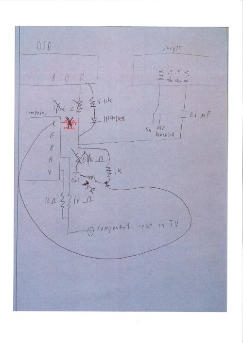
For the RGB lines I would be looking to replace R171, R172 and R173 with the 5600R and diode. Remove R179, R180 and R181. The holes left by R179-R181 could become our RGB insertion point. Use 75R to ground and 1000R inline on the RGB lines.
If you want external blanking connect the pin 16 to a diode and then to the R174 on the OSD chip side. (assuming you're getting 5V blanking signal). For internal blanking connect the output of the 5V regulator to the same place, possibly via a switch.
___________________________________________________
MarkOZLAD
OSD/External RGB Mux Diagram
OSD/External RGB Mux Resistor Value Table 0.7Vp-p : 0.5Vp-p
"Imagine toggle switch OSD modding a TV in 2019" - maxtherabbit
MarkOZLAD
OSD/External RGB Mux Diagram
OSD/External RGB Mux Resistor Value Table 0.7Vp-p : 0.5Vp-p
"Imagine toggle switch OSD modding a TV in 2019" - maxtherabbit
Re: TV RGB mod thread
For the moment I'm going to suggest to anyone that has a RGB modded consumer tv set and intends to use it with GScartlite should wire blanking to scart pin 8 which is 12v.
You will need to change resistor values ect but it will still work.
You will need to change resistor values ect but it will still work.
Re: TV RGB mod thread
Hello again, quoting myself here to give you a quick update and ask for some advice.
So far so good, I got a stable image on the TV, colors are well balanced with deep blacks. BUT, I see two issues:
1. Picture is too dark and colors look sorta washed out, with white tones showing up grey-ish instead. Overall I feel the image is lacking in brightness.
2. There is a little bit of ghosting in the image. This is more noticeable on hard edges (see this picture for an example, look at the "insert coin" letter N)
Initially I was feeding the 12V to the amp from the computers PSU, but image was even darker and 'snowy'. I later switched to a 12v1a power supply and image quality improved a lot, removing the noise and making colors more defined, but I'm still missing a more popping picture which I know this set can deliver.
I have already tried placing resistors of different values at the output of each line from the amplifier but I cannot get the picture to display properly on the screen, the colors look reversed instead.
boliva wrote:My TV is a Sony Trinitron Wega model KV-25FS120 (KV-24FS120 in the US) (schematics here: http://www.archivotecnicosaurios.com/de ... rvicio.pdf).
So I did just that, after many weeks and with lots of help (and patience) from lukilla, I built tim's DC VGA video amplifier, but replacing the 180 and 130 ohms resistors with 1k pots to better fine tune the values for my set. I am combining the VGA H and V syncs also using tim's dodgy diode circuit and feeding it through the component luma channel.Syntax wrote:Had a quick look but.
Internal OSD
No Teletext
No Component/RGB switch
Walk away......
cn301 is your best bet but that's going straight to the neck/tube.
So far so good, I got a stable image on the TV, colors are well balanced with deep blacks. BUT, I see two issues:
1. Picture is too dark and colors look sorta washed out, with white tones showing up grey-ish instead. Overall I feel the image is lacking in brightness.
2. There is a little bit of ghosting in the image. This is more noticeable on hard edges (see this picture for an example, look at the "insert coin" letter N)
Initially I was feeding the 12V to the amp from the computers PSU, but image was even darker and 'snowy'. I later switched to a 12v1a power supply and image quality improved a lot, removing the noise and making colors more defined, but I'm still missing a more popping picture which I know this set can deliver.
I have already tried placing resistors of different values at the output of each line from the amplifier but I cannot get the picture to display properly on the screen, the colors look reversed instead.
-
sparker599
- Posts: 6
- Joined: Fri Oct 13, 2017 7:17 am
Re: TV RGB mod thread
I modded my KV-27FV300. I used the same wiring as my last mod on page 42 of this thread, except with 470 ohm resistors for the inline resistors instead of 330 ohm. The OSD still is a bit dim compared to the RGB image (especially against the Mario 3 HUD), and games looks bighter on RGB than on composite or s-video, so I think something higher, about 680-900 ohms, would be ideal for my wiring.


Album with a couple more pics: https://imgur.com/a/t17Cj
Album with full size pics, but some duplicates (will remove those tomorrow) https://imgur.com/gallery/3tVQJ
Album with a couple more pics: https://imgur.com/a/t17Cj
Album with full size pics, but some duplicates (will remove those tomorrow) https://imgur.com/gallery/3tVQJ
Is there any reason you can't just use a pair of 1k resistors like I did in my mod? I made an external adapter that I can use to combine H and V together into a single RCA jack.Syntax wrote:I am combining the VGA H and V syncs also using tim's dodgy diode circuit and feeding it through the component luma channel.
Re: TV RGB mod thread
Very sad to report that Sony KV-2959T with cxa1465as is not moddable.
I know goxod modded a set with the same cxa but the brazilian version have the analogue rgb pins disabled. I even went into the service menu and altering the bits from 0 to 1 on the ID part would give me closed caption option but when you enter it, there's nothing.
Blanking works but all it shows is a black screen. If on rf the white noise screen becomes black. So blanking is working. Used pins 15,16,17,18 for the mod. The other RGB pins are digital so no use.
later I tried rgb directly into the neck board with Tim's board (scart to jamma) as it should amp the rgb signals.
The tv will not turn on with RGB wires hooked but if I turn it on and hook the wires to the board it will stop showing the OSD and the screen gets dark. Like some kind of protection.
This is the result:

upload pic
Lukilla or someone with experience on direct neck modding have any advice? should I cut the RGB wires from the tv board before soldering the rgb into the neck?
Also this set does not have G2 pot to rise brightness l, only focus on the flyback.
I know goxod modded a set with the same cxa but the brazilian version have the analogue rgb pins disabled. I even went into the service menu and altering the bits from 0 to 1 on the ID part would give me closed caption option but when you enter it, there's nothing.
Blanking works but all it shows is a black screen. If on rf the white noise screen becomes black. So blanking is working. Used pins 15,16,17,18 for the mod. The other RGB pins are digital so no use.
later I tried rgb directly into the neck board with Tim's board (scart to jamma) as it should amp the rgb signals.
The tv will not turn on with RGB wires hooked but if I turn it on and hook the wires to the board it will stop showing the OSD and the screen gets dark. Like some kind of protection.
This is the result:
upload pic
Lukilla or someone with experience on direct neck modding have any advice? should I cut the RGB wires from the tv board before soldering the rgb into the neck?
Also this set does not have G2 pot to rise brightness l, only focus on the flyback.
CapivaraGamer
http://capivaragamer.com.br
http://capivaragamer.com.br
Re: TV RGB mod thread
It was just the first thing I tried and it worked, I also tried combining the signals with 1k resistors and the result was exactly the same.sparker599 wrote:Is there any reason you can't just use a pair of 1k resistors like I did in my mod? I made an external adapter that I can use to combine H and V together into a single RCA jack.boliva wrote:I am combining the VGA H and V syncs also using tim's dodgy diode circuit and feeding it through the component luma channel.
Re: TV RGB mod thread
looks like we in latin america got the short end of the stick when it comes to moddable CRT setsfandangos wrote:Very sad to report that Sony KV-2959T with cxa1465as is not moddable.
I know goxod modded a set with the same cxa but the brazilian version have the analogue rgb pins disabled.
Yes, you need to cut off the wires coming from the board and place your own RGB and ground signals instead.fandangos wrote:Lukilla or someone with experience on direct neck modding have any advice? should I cut the RGB wires from the tv board before soldering the rgb into the neck?
Re: TV RGB mod thread
Excuse the crudeness of my edits but I think this would be better for the RGB circuits.sparker599 wrote:I modded my KV-27FV300. I used the same wiring as my last mod on page 42 of this thread, except with 470 ohm resistors for the inline resistors instead of 330 ohm. The OSD still is a bit dim compared to the RGB image (especially against the Mario 3 HUD), and games looks bighter on RGB than on composite or s-video, so I think something higher, about 680-900 ohms, would be ideal for my wiring.
Album with a couple more pics: https://imgur.com/a/t17Cj
Album with full size pics, but some duplicates (will remove those tomorrow) https://imgur.com/gallery/3tVQJ
If the 1k and twist method works, go with it. Plenty of other people use it.sparker599 wrote:Is there any reason you can't just use a pair of 1k resistors like I did in my mod? I made an external adapter that I can use to combine H and V together into a single RCA jack.Syntax wrote:I am combining the VGA H and V syncs also using tim's dodgy diode circuit and feeding it through the component luma channel.
___________________________________________________
MarkOZLAD
OSD/External RGB Mux Diagram
OSD/External RGB Mux Resistor Value Table 0.7Vp-p : 0.5Vp-p
"Imagine toggle switch OSD modding a TV in 2019" - maxtherabbit
MarkOZLAD
OSD/External RGB Mux Diagram
OSD/External RGB Mux Resistor Value Table 0.7Vp-p : 0.5Vp-p
"Imagine toggle switch OSD modding a TV in 2019" - maxtherabbit
Re: TV RGB mod thread
Bah it's not my quote.
Oi Mark did you just redraw our plans lol??
Oi Mark did you just redraw our plans lol??
Re: TV RGB mod thread
I wondered about that....Syntax wrote:Bah it's not my quote.
Oi Mark did you just redraw our plans lol??
Yeah, redrew....
___________________________________________________
MarkOZLAD
OSD/External RGB Mux Diagram
OSD/External RGB Mux Resistor Value Table 0.7Vp-p : 0.5Vp-p
"Imagine toggle switch OSD modding a TV in 2019" - maxtherabbit
MarkOZLAD
OSD/External RGB Mux Diagram
OSD/External RGB Mux Resistor Value Table 0.7Vp-p : 0.5Vp-p
"Imagine toggle switch OSD modding a TV in 2019" - maxtherabbit
-
comp1demon
- Posts: 32
- Joined: Sun Nov 12, 2017 6:30 pm
Re: TV RGB mod thread
Any Idea where to start for JVC AV27S33
I know it is a 600 line TV.
But can't seem to find too much info on it.
Would love to add RGB input to this.
I know it is a 600 line TV.
But can't seem to find too much info on it.
Would love to add RGB input to this.
Re: TV RGB mod thread
This tv uses a single micro/jungle chip so the OSD injection method will not work I'm afraidcomp1demon wrote:Any Idea where to start for JVC AV27S33
I know it is a 600 line TV.
But can't seem to find too much info on it.
Would love to add RGB input to this.
My cousin has this TV. An RGB to component converter looks very nice on his TV so that's an option for you at least.
Re: TV RGB mod thread
Checked out the schematic.comp1demon wrote:Any Idea where to start for JVC AV27S33
I know it is a 600 line TV.
But can't seem to find too much info on it.
Would love to add RGB input to this.
I find it very interesting that the TM8812CSANG3PF2 Jungle chip has the 21 Pin Ys right next to the 22 Cb In, 23 Y in and 24 Cr in. If you look at the block diagram these four pins all go to a block which mentions RGB matrix and Int/Ext switch.
I have so far been unable to find a datasheet for the TM8812CSANG3PF2. If you could find one that would be great because I believe there is a chance that Pins 21 - 24 could be:
21 Ys - Fast Blanking
22 Cb IN/Blue in
23 Y IN/Green in
24 Cr IN/Red in
...and bringing pin 21 high might allow RGB insertion instead of YUV.
Without a datasheet or direct experiment it is impossible for me to say for sure though.
If I am right you would be able to send RGB through the Cr/Y/Cb ports of the TV and Sync through AV1 port, tune to AV1 and trigger blanking into pin 21.
Need that jungle chip datasheet!!!
EDIT:
I have found datasheets for similar chips. It seems the Pin 21 Ys is for Picture in Picture YCbCr, not for RGB... Essentially you can be on a different input/tuner and the picture in picture can be triggered to show YCbCr content on top.
Still yet to find the exact datasheet
___________________________________________________
MarkOZLAD
OSD/External RGB Mux Diagram
OSD/External RGB Mux Resistor Value Table 0.7Vp-p : 0.5Vp-p
"Imagine toggle switch OSD modding a TV in 2019" - maxtherabbit
MarkOZLAD
OSD/External RGB Mux Diagram
OSD/External RGB Mux Resistor Value Table 0.7Vp-p : 0.5Vp-p
"Imagine toggle switch OSD modding a TV in 2019" - maxtherabbit
Re: TV RGB mod thread
Mark,
That would be great if you get this figured out! I was pretty disappointed when I found out I couldn't mod my cousin's TV the "easy" way.
That would be great if you get this figured out! I was pretty disappointed when I found out I couldn't mod my cousin's TV the "easy" way.
Re: TV RGB mod thread
I have edited my original reply. I was mistaken.cyborc wrote:Mark,
That would be great if you get this figured out! I was pretty disappointed when I found out I couldn't mod my cousin's TV the "easy" way.
___________________________________________________
MarkOZLAD
OSD/External RGB Mux Diagram
OSD/External RGB Mux Resistor Value Table 0.7Vp-p : 0.5Vp-p
"Imagine toggle switch OSD modding a TV in 2019" - maxtherabbit
MarkOZLAD
OSD/External RGB Mux Diagram
OSD/External RGB Mux Resistor Value Table 0.7Vp-p : 0.5Vp-p
"Imagine toggle switch OSD modding a TV in 2019" - maxtherabbit
Re: TV RGB mod thread
hey everyone. got myself another TV, it's a 25" Samsung, svc model CL25M5WKX/RCL. I haven't been able to locate the exact service manual but I found this one which I believe should be very close, if not the same, except for country specific model number variations. Any hints on where to start? Thank you in advance.
Re: TV RGB mod thread
It seems fandangos was modding a tv with the tda9592, dunno what happened in the end.boliva wrote:hey everyone. got myself another TV, it's a 25" Samsung, svc model CL25M5WKX/RCL. I haven't been able to locate the exact service manual but I found this one which I believe should be very close, if not the same, except for country specific model number variations. Any hints on where to start? Thank you in advance.
Re: TV RGB mod thread
boliva wrote:hey everyone. got myself another TV, it's a 25" Samsung, svc model CL25M5WKX/RCL. I haven't been able to locate the exact service manual but I found this one which I believe should be very close, if not the same, except for country specific model number variations. Any hints on where to start? Thank you in advance.
I think there may be a chance to mod this TV by putting RGB through the Component ports, Sync through AV1 and then sending between 0.9V and 3.0V into pin 45 of the jungle.
I do have concerns about the Component Y input though, it appears to be going through a circuit that I don't know what it is doing. May need to bypass that circuit for your Green input.
___________________________________________________
MarkOZLAD
OSD/External RGB Mux Diagram
OSD/External RGB Mux Resistor Value Table 0.7Vp-p : 0.5Vp-p
"Imagine toggle switch OSD modding a TV in 2019" - maxtherabbit
MarkOZLAD
OSD/External RGB Mux Diagram
OSD/External RGB Mux Resistor Value Table 0.7Vp-p : 0.5Vp-p
"Imagine toggle switch OSD modding a TV in 2019" - maxtherabbit
Re: TV RGB mod thread
Hi MarkOZLAD,
RGB lines @ ~5V or 0.7?MarkOZLAD wrote:I think there may be a chance to mod this TV by putting RGB through the Component ports
csync right?MarkOZLAD wrote:Sync through AV1
Would you care to elaborate a little bit? by bypassing the circuit you mean injecting the green component directly into one of the jungle pins?MarkOZLAD wrote:I do have concerns about the Component Y input though, it appears to be going through a circuit that I don't know what it is doing. May need to bypass that circuit for your Green input.
Re: TV RGB mod thread
0.7boliva wrote:Hi MarkOZLAD,
RGB lines @ ~5V or 0.7?
csync, composite video or lumaboliva wrote: csync right?
...good question!boliva wrote: Would you care to elaborate a little bit? by bypassing the circuit you mean injecting the green component directly into one of the jungle pins?
I was thinking you could intercept the Y line at Jumper J705 and run to a switch. Switch between the Y and 75-ohm terminated Green. If you used a double switch you could also hook up a 5V line there too.
If you are clever you maybe able to find a way snip the Y line after the 75 Ohm termination resistor R707 and send it to the switch so that you can use the factory Y port as your Green input.
___________________________________________________
MarkOZLAD
OSD/External RGB Mux Diagram
OSD/External RGB Mux Resistor Value Table 0.7Vp-p : 0.5Vp-p
"Imagine toggle switch OSD modding a TV in 2019" - maxtherabbit
MarkOZLAD
OSD/External RGB Mux Diagram
OSD/External RGB Mux Resistor Value Table 0.7Vp-p : 0.5Vp-p
"Imagine toggle switch OSD modding a TV in 2019" - maxtherabbit
Re: TV RGB mod thread
It seems fandangos was modding a tv with the tda9592, dunno what happened in the end.[/quote]lukilla wrote:
It was a philips 32 inches widescreen that I got at a tv repair shop. The owner said the tv was fine but I had my doubts.
I was able to add RGB to it but after half an hour of use it would start shaking the screen and the tv ended up switching off.
I had many problems with this set. The pins of the jungle broke, I had to use a dremel to solder on what left of it.
I ended up buying another jungle and replaced it.
later I removed some smd components (3 resistors) to be able to solder from osd IC and the jungle. It worked but after sometime it would start shaking the screen and it would switch off.
I don't know if the problem was there or was caused by the mod.
Also you need some kills to work on that small board.
I don't recommend this tv for rgb modding because it's difficult, unreliable and it's component input with my js technology component to rgb transcoder were identical. Philips sets have awesome component inputs compared to other sets. So I would recommend getting a transcoder because it's identical in PQ.
EDIT: sorry for the quick reply I'm texting from my phone while waiting for the dentist.
Also the tv went to the trash.
EDIT: Ok, now I'm back home and I've read that Boliva is trying to mod a samsung tv and not a philips one like mine.
I have no experience with Samsung sets, as far as I read online their tubes are not the best and not worth putting the effort into modding.
I remember I had some problems using current drop resistors for some reason with the TDA and I can't remember what worked in the end.
I remember I used 0.1uF ceramic caps (I use polyester for my mods now). Here are the only pictures I still have from the mod:


As you can see I used a solder bolder and some enamel wires to solder. The reason is to avoid putting some pressure and stress over such fine traces.
Hope this helps you.
Also those photos were taken before 75 ohm terminator resistor were added, at the time I was testing the results without it.
CapivaraGamer
http://capivaragamer.com.br
http://capivaragamer.com.br
Re: TV RGB mod thread
Holy cow, I don´t think my old solder iron could go over there  As for samsung, if it still got a punchy sharp picture for cheap/free why not?, back in the day in arcades you could find much worse
Btw I have a philips flat screen that has two circuits in the manual for the component inputs, one for yuv and the other for rgb "itv". I wonder what´s an itv?.
Btw I have a philips flat screen that has two circuits in the manual for the component inputs, one for yuv and the other for rgb "itv". I wonder what´s an itv?.
Re: TV RGB mod thread
Maybe interactive TV?lukilla wrote: Btw I have a philips flat screen that has two circuits in the manual for the component inputs, one for yuv and the other for rgb "itv". I wonder what´s an itv?.
Ok, remember that KV-2959T that I was trying to mod for RGB and the analog pins were disabled?
Well it's possible to enable those.
This tv came with a few problems:
1. Tons of dirty inside that I could barely see the boards.
2. Wavy screen.
3. The input 2 (video 2) wasn't showing up.
If you guys followed my last posts I was trying to do a direct neckboard modding since the TV wouldn't enable the analogue RGB pins.
Using Tim boards I tried my best to work with G2 on the neck (this model have it on the neckboard instead in the flyback), tweaking the contrast knob and the brightness.
No deal, the image was always too dark and the tv wouldn't power on without the RGB amp pins connecting to the neck.
I was able to power on the TV with 2.2K resistors but either way terrible results.
So I figured out how to enable the pins in this set. You need to set everything on the ID side of the service menu to 1. Each bit enables something, like close caption.
The trick is do this and reset the service menu with 8 + enter.
This will enable the pins and leave the ID side intact.
So after getting RGB I was getting some wavy image on the left and right side of the screen.
Tried resoldering the flyback and everything else, without success.
Swapped all electrolytic on the deflection side and it's almost entirely gone.
After assembling everything I just grounded pins 21 (main shield) and did a jumper to pin 2 (audio ground).
Well, I guess I should have bridged every single gnd pin on the scart end. I'm getting buzzing audio like poorly shielded cables.
Besides that I learned that different GND points make a difference.
Also long gnd cable near the flyback makes the image much brighter. If you just put the flyback cable near the gnd cable you get a very strong white ringing effect.
Next weekend I'll open up this TV again to fix the grounding and consequently buzzing sound, at least I hope.
I enjoy this set for personal reasons, this were the first tv I saw a PS1 hooked and those black plastic tvs are way more nostalgic for me.
Also this tv has almost perfect convergence and has a curvature similar to a PVM, which I enjoy.
Well finally, here are some pictures:
url=https://ibb.co/hyry87]
 [/url]


PS: Menu uses digital RGB pins, so RGB plus OSD Menu is fine.
CapivaraGamer
http://capivaragamer.com.br
http://capivaragamer.com.br