
If you look at your first post, Mark responded to you and asked for more information.BevelTipDrip wrote: Anybody have any input? I've decided to add a fourth BNC with a sync stripper that goes into one of the composite lines. I'll let people know how it works, I'm going to write up this mod when I am done because it's fairly simple, but also a pain in the ass haha.
TV RGB mod thread
Re: TV RGB mod thread

Re: TV RGB mod thread
Why would anyone use a THS amp to buffer RGB input to a jungle?
Its a waste of time.
A sync stripped signal will not help full blanking. Check/isolate the blanking pin/s and sweep them with a pot from 0-5v.
Make sure you are using 100n caps for clamping if the pics off.
Its a waste of time.
A sync stripped signal will not help full blanking. Check/isolate the blanking pin/s and sweep them with a pot from 0-5v.
Make sure you are using 100n caps for clamping if the pics off.
-
obitus1990
- Posts: 12
- Joined: Thu Dec 13, 2018 4:30 pm
Re: TV RGB mod thread
Cool, thanks for the link! I did exactly as he described in his video, which is very close to how I had attempted this before with no luck. I am getting the same exact result as with my prior attempt in that every time I plug a source into the TV (which has already been put into blanking mode by pulling YBl high) the GFI outlet that the source and TV are plugged into trips immediately. It happens immediately upon plugging in the source to the input, with power off on both the set and the source. Anyone have any ideas as to what causes this, as I can't figure it out. Thanks!Dildaria wrote:https://www.youtube.com/watch?v=RhhxpW_Bxtk
Looks like it is possible to mod that Orion
Re: TV RGB mod thread
Please dont kill yourself.
Sounds like your modding an old RF only set right?
I bet it has a HOT/live chassis.
Do some research about old CRT live chassis before you die, and go buy your circuit breaker something nice for saving you thus far.
Sounds like your modding an old RF only set right?
I bet it has a HOT/live chassis.
Do some research about old CRT live chassis before you die, and go buy your circuit breaker something nice for saving you thus far.
Re: TV RGB mod thread
For a HOT chassis, you have to use an isolation transformer. https://en.wikipedia.org/wiki/Isolation_transformer
In North America, you can't scope ANY TV if the internals are in any way referenced to chassis ground because the ground plug is tied to the neutral in the circuit breaker. Doing so will probably just trip it, but it could also blow something up if it's not quick enough.
I use an isolation transformer for everything. It doesn't make it "safe," but it reduces the chance you end up in a more potentially lethal situation.

Re: TV RGB mod thread
Here’s a paint diagram I made for my isolation transformer setup.

Copyright 1987
-
obitus1990
- Posts: 12
- Joined: Thu Dec 13, 2018 4:30 pm
Re: TV RGB mod thread
It is RF only, made in 1997. Only a coax connector that leads to the tuner, through which I had a VCR and cable TV connected back in the day. I have and read the full service manual before anything, and there's no mention of having a hot/live chassis, so, I will admit it is not something I had checked for. No warning labels anywhere else that indicate it is HOT/Live. No metal tray with grounding wires tied to it for the PCB to sit upon -- everything plastic inside. It has a polarized plug, but no separate third ground terminal (conventional US plugs) unless that in itself indicates it is HOT. Does any of that sound like it has a hot/live chassis?Syntax wrote:Please dont kill yourself.
Sounds like your modding an old RF only set right?
I bet it has a HOT/live chassis.
Do some research about old CRT live chassis before you die, and go buy your circuit breaker something nice for saving you thus far.
I simply followed all the instructions to the letter in the YouTube link another user had posted about modding this exact TV. It looked pretty self explanatory and simple that even someone like me with moderate electronic repair skills could handle.
I can thank the GFCI outlet, but also the info on this forum (and plain common sense) for teaching me the following: what not to touch (including capacitors), to unplug it from mains supply from the wall before doing anything, discharge the CRT with a proper HV probe, multiple times, and then disconnect the anode, neckboard, and all other connection points to the tube. I also check again before reconnecting the anode to make sure there's no buildup of charge from tube capacitance. Heck, after reassembling, I don't even make the connection between the TV and the source without first unplugging everything from the wall. It's only when I plug it back in to power then turn on the power strip that the GFCI trips, showing me something is wrong.
Is this a lost cause? It's maddening because there's obviously someone who got this to work using the method I copied from his video.
Re: TV RGB mod thread
Absence of evidence is not evidence of absence. Many sets that were RF have common referenced to earth, it's more likely than fancy newer sets actually.obitus1990 wrote: No warning labels anywhere else that indicate it is HOT/Live.
Watch this to learn about isolation transformers: https://www.youtube.com/watch?v=vz70GSBhYjA&t=1564s
However, I would recommend you not mess around with it anymore. I'm not trying to be snarky or anything, but no one here wants you to hurt yourself, and you clearly are pretty new to a lot of these concepts. Working inside a TV is always going to carry some risk of death by electrocution, so you should endeavor to get better acquainted with electronics and electricity in general before you do so. If you make the wrong mistake, it's the last one you will ever make.
Re: TV RGB mod thread
Every single RF only set I've seen has had a hot chassis. That design allows the manufacturer to eliminate several components from the power supply section, which was critical to saving costs on these low budget TVs.
Generally, modding these sets is a bad call. It is disappointing because they're the ones that would benefit most from it.
Generally, modding these sets is a bad call. It is disappointing because they're the ones that would benefit most from it.
-
obitus1990
- Posts: 12
- Joined: Thu Dec 13, 2018 4:30 pm
Re: TV RGB mod thread
Thanks for the link about the isolation transformer. That was very helpful. I really hate to sidetrack the thread by continuing on, so apologies for the following.
This is one of my only forays into HV, or, anything which has the actual AC supply coming into the board itself, which is something I have always avoided due to fear/respect. Sharing a video like that with me has helped increase my knowledge on the subject, and I appreciate it.
Now for the really dumb question regarding the isolation transformer: If I connect the TV to an isolation transformer, thereby eliminating the "earth ground reference" from the equation, will that then stop the GFCI at the wall socket from tripping? If so, does that mean that the problem still exists (meaning a short which can still kill me or destroy the video source), but is now being "masked" by being unable to trip the GFCI?
I am thinking, but, could be wrong, that it fixes the problem.
Tell me if my understanding below is incorrect, please.
Neutral is bonded to earth ground, from the pole, on a three prong receptacle.
On an RF set like this, there is only a two pronged polarized plug, with the neutral side sharing "ground" with the other circuitry of the TV, instead of having a discreet ground like a 3 prong plug would. It is considered "floating" in this state.
As soon as one adds an external input, like composite or 75 Ohm terminated RGB and Sync signals, grounding them to the PCB, things are OK until you plug something else into it.
This then sends the neutral from the TV down the ground wire of the cable leading to the connected device (say, an old console), which the GFCI interprets as a short to ground, tripping it.
Since a properly wired isolation transformer has no such connection to earth ground on the secondary coil, the GFCI isn't tripped because there's no return path to earth ground on the secondary coil.
Yes/no?

Re: TV RGB mod thread
Got done modding a KV-20FS12 with a BA-5 chassis.
Everything works but when I went into the service menu to fix the rgb shift I noticed some of the picture is cut off,I used a 2.2k resister for blanking.
https://i.imgur.com/5nUJNjQ.jpg
This set only has two composite inputs,I'm tempted to add svideo and use luma as sync but you guys have any clue whats going on.
Re: TV RGB mod thread
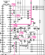
Hello everyone, I apologize for the text in English, it's not my own. There is a sony kv-14vm1 TV on the BC-2 chassis, based on the CXA1213BS / CXA1213AS jungle, the image signal goes through the CXA1214P region decoder. Where do I need to solder the RGB pins? And is it possible to make such a modification.
Datasheet TV:
https://elektrotanya.com/sony_ch_bc-2_k ... ad.html#dl
Datasheet Jungle:
https://datasheetspdf.com/pdf/489066/Sony/CXA1213AS/1
Datasheet Decoder:
https://datasheetspdf.com/datasheet/CXA1214P.html
Datasheet TV:
https://elektrotanya.com/sony_ch_bc-2_k ... ad.html#dl
Datasheet Jungle:
https://datasheetspdf.com/pdf/489066/Sony/CXA1213AS/1
Datasheet Decoder:
https://datasheetspdf.com/datasheet/CXA1214P.html
Re: TV RGB mod thread
I'd be looking at the "Left Blanking Adjustment" LBLK in the service menu.Pikkon wrote:Got done modding a KV-20FS12 with a BA-5 chassis.
Everything works but when I went into the service menu to fix the rgb shift I noticed some of the picture is cut off,I used a 2.2k resister for blanking.
https://i.imgur.com/5nUJNjQ.jpg
This set only has two composite inputs,I'm tempted to add svideo and use luma as sync but you guys have any clue whats going on.
___________________________________________________
MarkOZLAD
OSD/External RGB Mux Diagram
OSD/External RGB Mux Resistor Value Table 0.7Vp-p : 0.5Vp-p
"Imagine toggle switch OSD modding a TV in 2019" - maxtherabbit
MarkOZLAD
OSD/External RGB Mux Diagram
OSD/External RGB Mux Resistor Value Table 0.7Vp-p : 0.5Vp-p
"Imagine toggle switch OSD modding a TV in 2019" - maxtherabbit
Re: TV RGB mod thread
Thanks,that did help,would have not thought to use it.
Only thing it would not fill the entire left side,it's still cut off but way better than before,you think modding the set for s video and using luma as sync would fix the problem.
Only thing it would not fill the entire left side,it's still cut off but way better than before,you think modding the set for s video and using luma as sync would fix the problem.
Re: TV RGB mod thread
You may not have to do a complete S-Video mod.
What would probably work is if you enable the S-Video input in the service menu, and input the sync to pin 4 of the jungle chip via a 10uF capacitor. There are a bunch of other missing components in the S-Video circuit, but you probably don't need these if all you want is to sync your RGB signal.
To enable S-Video, go the service menu and change ID-1 from 3 to 19.
Re: TV RGB mod thread
Thanks for the response.
I did follow the guide BazookaBen wrote but thought I could maybe get away without the video switching ic as I had the other parts with me but I couldn't get it to work,the ic is cheap so I'll pick one up online.
I did follow the guide BazookaBen wrote but thought I could maybe get away without the video switching ic as I had the other parts with me but I couldn't get it to work,the ic is cheap so I'll pick one up online.
Re: TV RGB mod thread
The issue you showed in the pictures was a horizontal blanking issue. Adding the S-Video should enable you to change the left shift but I don't think will have any affect on the horizontal blanking/left side being cutoff.Pikkon wrote:Thanks,that did help,would have not thought to use it.
Only thing it would not fill the entire left side,it's still cut off but way better than before,you think modding the set for s video and using luma as sync would fix the problem.
___________________________________________________
MarkOZLAD
OSD/External RGB Mux Diagram
OSD/External RGB Mux Resistor Value Table 0.7Vp-p : 0.5Vp-p
"Imagine toggle switch OSD modding a TV in 2019" - maxtherabbit
MarkOZLAD
OSD/External RGB Mux Diagram
OSD/External RGB Mux Resistor Value Table 0.7Vp-p : 0.5Vp-p
"Imagine toggle switch OSD modding a TV in 2019" - maxtherabbit
Re: TV RGB mod thread
Pikkon wrote:Thanks,that did help,would have not thought to use it.
Only thing it would not fill the entire left side,it's still cut off but way better than before,you think modding the set for s video and using luma as sync would fix the problem.
I know this is pretty obvious, but since you didn't mention it, did you adjust the HSIZ and HPOS after reducing the Left Blanking?
That chassis also has a service menu option to turn off all horizontal blanking, so you could try that in addition to it's dedicated Left and Right side Blanking controls.
Re: TV RGB mod thread
I did adjust it using HSIZ and HPOS and putting horizontal blanking to 1 in the service menu did make it fuller but was still cut off,only kind of fix I found was adjusting the SYSC(Color System)to 7 and that made the left side full and looks great in rgb,only drawback is it makes composite look pretty bad but not that big of a deal.
Re: TV RGB mod thread
It's not uncommon for sets to have different "centers" for different inputs. My PVM has obviously different centers for RGB, Composite and S Video, and that's just stock with no modding or anything.Pikkon wrote:only drawback is it makes composite look pretty bad but not that big of a deal.
Re: TV RGB mod thread
The main issue with BA-5s (and some BA-4Ds) is that the composite input runs through the comb filter, which causes some delay. S-Video, meanwhile, goes straight to the jungle chip.
Re: TV RGB mod thread
Could try changing the Y-Delay (YDEL) in service menu.matt wrote:The main issue with BA-5s (and some BA-4Ds) is that the composite input runs through the comb filter, which causes some delay. S-Video, meanwhile, goes straight to the jungle chip.
___________________________________________________
MarkOZLAD
OSD/External RGB Mux Diagram
OSD/External RGB Mux Resistor Value Table 0.7Vp-p : 0.5Vp-p
"Imagine toggle switch OSD modding a TV in 2019" - maxtherabbit
MarkOZLAD
OSD/External RGB Mux Diagram
OSD/External RGB Mux Resistor Value Table 0.7Vp-p : 0.5Vp-p
"Imagine toggle switch OSD modding a TV in 2019" - maxtherabbit
Re: TV RGB mod thread
Theres a phisical switch/toggle to change the horizontal position in my BA-5. That fixed the "offscreen to the left" for me. Check my post in MarkOZLAD RGB mux thread.
Re: TV RGB mod thread
Oh, is it one of those Sonys that has the weird horizontal toggle that gives it a few different positions? I have one of those.Gonzalo wrote:Theres a phisical switch/toggle to change the horizontal position in my BA-5. That fixed the "offscreen to the left" for me. Check my post in MarkOZLAD RGB mux thread.
-
megasdkirby
- Posts: 1
- Joined: Mon May 03, 2021 11:10 pm
Re: TV RGB mod thread
Hello everyone!
I've been checking out the forums, particularly the RGB mod section, as I have many CRTs I would like to mod. The first unit to test out was a Curtis Mathes 19" CRT, model CM19011BX. I found the jungle chip and it's a TN1282N. The chassis is a K15A AA41-11037C. The OSD chip is SZM-370TH1. Looking at the schematic, it's almost identical to the CRT modded by the 8-bit guy on his Youtube video a few years ago, with the only differences been the size of the unit (his was a 13" while this one is 19"), the model of the MICOM and Jungle Chip, and finally some capacitors and diodes here and there. While this may seem like everything is different, the reality is that, by looking at the schematic, it was eerily similar, so I decided to start with this one, as I have a reference to go by.
Using the methods in both videos, I did manage to RGB the unit and it looks BEAUTIFUL! Crisp, detailed image...so gorgeous. MarkOZLAD helped me quite a bit to understand some of the reasons behind certain steps, so an awesome THANK YOU for the help!
However, there are issues. The least important one being that after the mod, the screen in RGB mode looked too bright. MarkOZLAD recommended that I lower the brightness on the flyback, which I did, and now it looks fantastic. Problem solved for that issue. The main issue that still haunts me is an OSD issue. For some reason, even when the 5V and all the wires are correct and the switch is configured correctly (as in 8-bit guy's second video), the unit will keep displaying the "VIDEO" and "PLEASE INSERT AV CONNECTION" on the screen. It happens in RGB mode, non RGB mode, and even while playing a game. Even the remote display button doesn't help. So something is a miss. I rechecked all connections and everything is in order. Made sure I used the correct sections for voltage and ground, as well as jump the resistor for the CCD, and that is ok as well. As a last resort, I disconnected the three pins 22-24, the RGB pins from the MICOM, and that helped make the message disappear while on RGB mode, but in non RGB mode part of it remains. Odd.
So, refering to the schematic pics above (please note they are not from the unit but from a nearly identical unit. I could never find the service manual for my CRT but managed to find a unit using the same chassis and ICs, which helped immensely), I did the following:
-Insert the RGB lines between the exiting resistor and the 75ohms resistor and grounding it (as was done on the video with the "mini triangles".
-Jump RU10 680ohm resistor to cancel out the CCD
-Contrary to the picture of the schematic of the jungle chip, the diodes shown were not available on my unit.
-Found the 5V and GROUND on CN901 (Adjustment Port) and wired the 5V on ther third leg of the switch and the ground was left on standby for the time being (not used until testing the SMS)
-Lifted the leg of the resistor (R919) closest to the MICOM and soldered a cable to the leg to the middle pin of the switch. Then I inserted another leg in the now available hole and soldered that to the remaining leg of the switch.
-C919 and C916 are not found on my unit
With this setup, the mod works as mentioned above, but the text kept appearing. So I desolered the leg closest to the MICOM chip for resistors R916-R918, breaking the pathway. This made the onscreen text disappear once and for all.
Granted, by adjusting the flyback it made non RGB mode waaaaay to dark to even be considered playable, but RGB is just perfect and beautiful. Tehnically, it seems I'm pretty much done, but if I can make the OSD menu appear and disappear at will while on RGB mode, that would be fantastic and would put an end to this mod.
Any ideas? Thanks everyone!
Re: TV RGB mod thread
Your 5v blanking line was back feeding into the micron and activating it?
Diode should sort that.
Dropping the screen voltage to get ideal brightness doesn't seem right.
Does 240p test suit color bars look ok or black crush?
Double check your termination total or test .5vpp video if so.
Diode should sort that.
Dropping the screen voltage to get ideal brightness doesn't seem right.
Does 240p test suit color bars look ok or black crush?
Double check your termination total or test .5vpp video if so.
-
maxtherabbit

- Posts: 1763
- Joined: Mon Mar 05, 2018 4:03 pm
Re: TV RGB mod thread
+1 to all of thisSyntax wrote:Your 5v blanking line was back feeding into the micron and activating it?
Diode should sort that.
Dropping the screen voltage to get ideal brightness doesn't seem right.
Does 240p test suit color bars look ok or black crush?
Double check your termination total or test .5vpp video if so.
Re: TV RGB mod thread
Not sure how it can be feeding back when the leg has been lifted out of circuit....Syntax wrote:Your 5v blanking line was back feeding into the micron and activating it?
___________________________________________________
MarkOZLAD
OSD/External RGB Mux Diagram
OSD/External RGB Mux Resistor Value Table 0.7Vp-p : 0.5Vp-p
"Imagine toggle switch OSD modding a TV in 2019" - maxtherabbit
MarkOZLAD
OSD/External RGB Mux Diagram
OSD/External RGB Mux Resistor Value Table 0.7Vp-p : 0.5Vp-p
"Imagine toggle switch OSD modding a TV in 2019" - maxtherabbit
Re: TV RGB mod thread
Was feeding back, leg was lifted, switch was used, diode could be used instead of lifted leg and switch.
That's how.
Ill probs try to add a diode on that Panasonic I have that always has a grey AV in the corner and see if it shuts it up.
That's how.
Ill probs try to add a diode on that Panasonic I have that always has a grey AV in the corner and see if it shuts it up.
-
KPackratt2k
- Posts: 229
- Joined: Sun Apr 04, 2021 11:02 pm
- Location: Seattle, WA, USA
Re: TV RGB mod thread
Now that I'm done modding the RCA E13309 13" TV, I've decided to move onto my Sony KV-20EXR20 20" TV. Even though this model lacks Picture-in-Picture, the PIP header (A-31) is still active as I was able to blank the screen by applying voltage to the YS pin, which should make it ready to go without having to use an I2C modchip. I've put together a quick diagram for modding and I'd like to know if there's anything else that I need to do with it before I proceed.
WIP Mod Diagram: https://imgur.com/a/dkCX1ZA
Service Manual: https://elektrotanya.com/sony_anu2_chas ... nload.html
EDIT: Ignore the blanking diagram in the Imgur album as I've mistakenly used the Standby 5V regulator (IC601) rather than the set's actual 5V regulator (IC604), which I should've used in the first place.
On the model with PIP (KV-27EXR25), there are 100 ohm resistors between the jungle chip (CXA1313S) and the A-31 header. I've added three 100 ohm resistors on the RGB lines (R316-R318) and a 150 ohm resistor on the YS line (R319) as suggested by a previous post for better handling of the higher blanking voltage. Does this sound like the right thing to do or should I remove the resistors?
EDIT: Turns out the added resistors are required as the blanking didn't work without them. See my later post on the next page for proof.
Last edited by KPackratt2k on Tue May 25, 2021 7:51 am, edited 1 time in total.