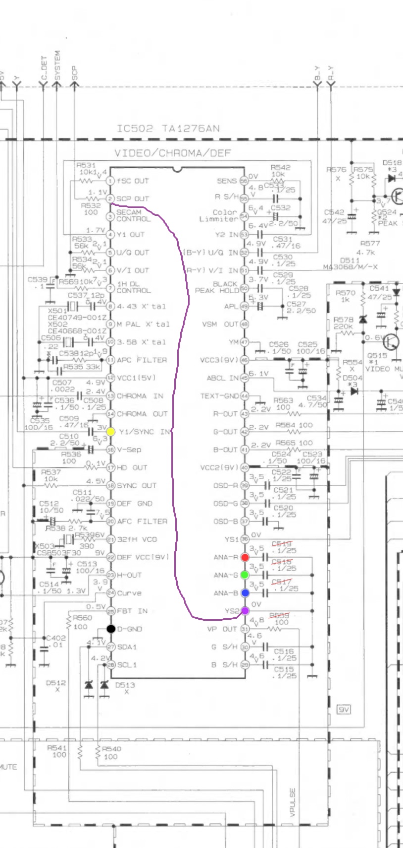
Remove Caps and resistors from sync line, inject at composite video input instead and choose appropriate input. Instead of pulling YS2 voltage from some random capacitor, take 5V from pin 12. Ensure proper pulldown (10K) from YS2/pin 32 to GND.darkcrono wrote:Still having problems with banding in the bright colors mostl, the image
https://imgur.com/ryAgqys
104 cap in the sync line
Any advice?
Hacking RGB into a jvc TM-H150cg 15" and JVC TM-H1700G 17"
Re: Hacking RGB into a jvc TM-H150cg 15" and JVC TM-H1700G 1
Re: Hacking RGB into a jvc TM-H150cg 15" and JVC TM-H1700G 1
Thanks, will try
Re: Hacking RGB into a jvc TM-H150cg 15" and JVC TM-H1700G 1
Took 5v from jungla pin12, measured 4.99v on it, and took it to ys2, what i don't really understand is how to pull down it to ground, right now the image is a little worse 
Re: Hacking RGB into a jvc TM-H150cg 15" and JVC TM-H1700G 1
This should really not affect video quality, it's simply the right to do. You just put a 10K resistor between ys2 and GND. This is only if you want to keep composite video option also. What should work best for sync (and thus picture) is either inserting sync at composite video input or possibly S-Video Y Pin.darkcrono wrote:Took 5v from jungla pin12, measured 4.99v on it, and took it to ys2, what i don't really understand is how to pull down it to ground, right now the image is a little worse
Re: Hacking RGB into a jvc TM-H150cg 15" and JVC TM-H1700G 1
Thanks for the fast reply, as i read in the tutorials, the ys2 blanking expects 0,8v this 5v wouldn't be too much?
Re: Hacking RGB into a jvc TM-H150cg 15" and JVC TM-H1700G 1
This is somewhat of a misconception as I see it. The datasheet of the TA1276AN (the jungle) specifies that *above* 0.75V it will select Analog RGB Inputs. It's a treshold, also a quite normal one for TTL logic, to represent logic low, when below, and then high at a certain voltage above this (here it seems it switches at this point). I've modded many JVCs using this, without issues. If you are not going to switch to composite, meaning not inserting the pulldown, then you could, for the sake of power consumption, insert a 1K resistor. If you're going to switch with a switch between 5V and GND, with 5V for RGB, and 0V/GND for composite, you can do the same (insert 1K resistor), and leave out the pull down. If you're going to use SCART, insert the pulldown, and connect pin 16 from SCART to YS2.darkcrono wrote:Thanks for the fast reply, as i read in the tutorials, the ys2 blanking expects 0,8v this 5v wouldn't be too much?
Last edited by skum on Fri Aug 02, 2019 10:18 pm, edited 2 times in total.
Re: Hacking RGB into a jvc TM-H150cg 15" and JVC TM-H1700G 1
Serious talk here, won't doubt any word from now on, i don't want to preserve the composite in, so the pull down seems not to be necesary, will try to check every other connection, but with no caps in the sync, the image goes wild.
Re: Hacking RGB into a jvc TM-H150cg 15" and JVC TM-H1700G 1
OK, so for the sake of completeness then, insert a 1K resistor from 5V to YS2 (this is purely "cosmetic"). No pulldowns or whatever. Remove all resistors and capacitors from your sync line and solder it to the pin of composite input A, meaning right at the input, on the PCB side of the BNC plug. Select input A with the buttons. If your monitor has external sync option, you should honor this. Meaning if you have it set for external sync, apply sync line here instead (at the BNC pin) and if you have it set for internal sync, apply at the input.darkcrono wrote:Serious talk here, won't doubt any word from now on, i don't want to preserve the composite in, so the pull down seems not to be necesary, will try to check every other connection, but with no caps in the sync, the image goes wild.
EDIT: It seems your monitor does not have external sync, so use the input.
Re: Hacking RGB into a jvc TM-H150cg 15" and JVC TM-H1700G 1
Changing the cap in the sync line, really improves the stability of the image, tomorrow i will go to the place to try your instructions
Re: Hacking RGB into a jvc TM-H150cg 15" and JVC TM-H1700G 1
Okay, moved the sync line to the A input bnc's solder, with no cap in the wire, image is rock steady, absolutely no wave at all, the only problem left is that the image is off center and the menú won't let me center it, any suggestion?
https://imgur.com/a/UtSo4J0
https://imgur.com/a/UtSo4J0
Re: Hacking RGB into a jvc TM-H150cg 15" and JVC TM-H1700G 1
All resistors and whatnot on the line are also gone right? No 75 Ohm, 30 Ohm and so on? What is your sync source?darkcrono wrote:Okay, moved the sync line to the A input bnc's solder, with no cap in the wire, image is rock steady, absolutely no wave at all, the only problem left is that the image is off center and the menú won't let me center it, any suggestion?
https://imgur.com/a/UtSo4J0

Re: Hacking RGB into a jvc TM-H150cg 15" and JVC TM-H1700G 1
From the looks of it you tried the H-pos on the quick menu, but did you try the service menu?darkcrono wrote:Okay, moved the sync line to the A input bnc's solder, with no cap in the wire, image is rock steady, absolutely no wave at all, the only problem left is that the image is off center and the menú won't let me center it, any suggestion?
https://imgur.com/a/UtSo4J0
Re: Hacking RGB into a jvc TM-H150cg 15" and JVC TM-H1700G 1
Star1 wrote:From the looks of it you tried the H-pos on the quick menu, but did you try the service menu?darkcrono wrote:Okay, moved the sync line to the A input bnc's solder, with no cap in the wire, image is rock steady, absolutely no wave at all, the only problem left is that the image is off center and the menú won't let me center it, any suggestion?
https://imgur.com/a/UtSo4J0
Star1: how to get to that menu?
Skum: the sync line is clear of any component, from scart composite to the line A bnc.
Re: Hacking RGB into a jvc TM-H150cg 15" and JVC TM-H1700G 1
There is a specific button combo, but you'll want the service manual, as the geometry functions (and everything else) is just numbered.
Send me your email in a pm, and I will send the service manual as soon as I have a chance.
Send me your email in a pm, and I will send the service manual as soon as I have a chance.
Re: Hacking RGB into a jvc TM-H150cg 15" and JVC TM-H1700G 1
Really, really, really grateful to star1 for the manuals and directions on where to look, the image now is centered and i can configure every aspect of it.
Also to Skum the image waving was solved thanks to him.
You both MVP, and everyone helping in this thread.
For the sake of curiosity, is it posible to check the hoir meter? In the manual c23 says hour meter but it doesn't display it
Also to Skum the image waving was solved thanks to him.
You both MVP, and everyone helping in this thread.
For the sake of curiosity, is it posible to check the hoir meter? In the manual c23 says hour meter but it doesn't display it
Re: Hacking RGB into a jvc TM-H150cg 15" and JVC TM-H1700G 1
Glad to be of help!
I can't say for sure, but since the hour meter indicator needs to be multiplied by 100, perhaps it will show as 000 unless it has more than 100 hours of use?
Or perhaps there is a way of resetting it..
I can't say for sure, but since the hour meter indicator needs to be multiplied by 100, perhaps it will show as 000 unless it has more than 100 hours of use?
Or perhaps there is a way of resetting it..
Re: Hacking RGB into a jvc TM-H150cg 15" and JVC TM-H1700G 1
Hi, question about modding a JVC TM-H140PN.
Can i use 1,1 Volt for blanking signal? Plan was to use a wire from SCP out pin to YS2. Shown in the picture.
Blanking signal need 0,7-5 Volt switch to RGB.
Does it work with 1,1v? Thanks an greetings.
https://s19.directupload.net/images/191218/qel43dqu.jpg
Can i use 1,1 Volt for blanking signal? Plan was to use a wire from SCP out pin to YS2. Shown in the picture.
Blanking signal need 0,7-5 Volt switch to RGB.
Does it work with 1,1v? Thanks an greetings.
https://s19.directupload.net/images/191218/qel43dqu.jpg
Re: Hacking RGB into a jvc TM-H150cg 15" and JVC TM-H1700G 1
Wow its been a year since, jeez haha !What voltage do you measure on pin 32 when you're in input D? And all the GNDs should be tied together and into the units' GND. Technically only one should be enough, but it depends on how its connected in from the source. What "female RGB connector" are you using? BNC? SCART?
I've just started looking into this again as it wont defeat me ! I've measured the voltage and its 8V I get on pin32 whilst on input D, all the RGB pins on the PVM circuit board are showing 3.5V, including the sync on PIN 15.
On the female scart end im about to tie all the RGB GND's together
Re: Hacking RGB into a jvc TM-H150cg 15" and JVC TM-H1700G 1
Ok, answering 1 year old question: Even though it might work, DONT take some random pin and use that for blanking, coupling some random output to a random input is a really bad choice. Use a VCC 5V or whatever.nexus23 wrote:Hi, question about modding a JVC TM-H140PN.
Can i use 1,1 Volt for blanking signal? Plan was to use a wire from SCP out pin to YS2. Shown in the picture.
Blanking signal need 0,7-5 Volt switch to RGB.
Does it work with 1,1v? Thanks an greetings.
https://s19.directupload.net/images/191218/qel43dqu.jpg
That being said, the H140PN needs I2C interception, some info here: https://immerhax.com/?p=558
-
me@danieldoyle.com
- Posts: 7
- Joined: Mon Sep 13, 2021 5:03 pm
Re: Hacking RGB into a jvc TM-H150cg 15" and JVC TM-H1700G 1
Hi folks, I know this is a pretty old thread but maybe someone involved is still kicking around. Anyway I'm having trouble with this mod for the TM-1900G, I'm trying to follow @soviet992's directions / a youtube video directions. I have a little voltage divider circuit to bring my input RGB voltages to 0.5vp-p, I am pulling the blanking voltage through a switch off C129 to pin32 on the jungle (measures as 2.2V for me, guess it just needs to be >.7V) and I'm trying to reuse sync via feeding composite sync to the composite input. The blanking seems to work fine since I can feed it an actual input and flip my switch and it blanks the video. However with my voltage divided RGB to pins 33-35 and my csync on input A I get no picture at all on the monitor. Not even any kind of attempt at sync or showing any picture. I've tried both a SNES and a MiSTer as input sources.
Youtube that does basically the same thing as @soviet992
https://www.youtube.com/watch?v=kBHjBtBqQUg&t=686s
My actual mod attempt:
https://imgur.com/a/KmyQD6N
Keep in mind I'm using perfboard so all the points are independent and my inputs are coming in from the bottom in that pic. Also using 24 & 51 ohm resistors in the voltage divider per the youtube to get to 75ohms measure at ground and ~.5v to the 100nf cap. Finally I've also tried feeding sync directly to pin 15 but with no luck there either. I get nothing at all, not even a bad picture, just nothing. Regular composite and svideo both work great for both inputs when blanking switch is off.