
You have a v1.0 board with v0.50 firmware, for clarity.mtn360 wrote:Hey folks,
a while back I was lucky enough to have zeruel85 assembling a digital AV interface and pre-install it into an A board he got for me as well (you rock man!) ..
I'm very happy with the thing (thanks marqs for the board design + software) and zeruel85 again for the installation.
It was until just recently tho that I realized some issues with A/V getting out of sync on my LG OLED over time. In fact, if I keep it running for a few minutes the lag keeps adding up to multiple seconds and counting.
I tried it on my capture card as well for some streaming. Instead of A/V going out of sync, I was getting some distortion in a fixed interval (maybe every 1-2 sec, can't recount) ...
From a pure listening diagnose it seems like the audio egressing from the interface is not fully fitting the buffer size expected by the receiver. I might be totally wrong tho!
Maybe zeruel85 can recall which version he installed on the board?
Any suggestions are highly appreciated as I wanted to make another (more in-depth) demo of the board. I did a quick test recording before: https://www.youtube.com/watch?v=Y-UKe9wtjHU
I recorded the issues with both setups, direct recording from capture card + camera recording of my tv. Please use headphones when listening to both, as you might not hear the gap/distortion within the audio captures.
https://mega.nz/fm/97RkTaSI
CPS2 digital AV interface
Re: CPS2 digital AV interface

Re: CPS2 digital AV interface
marqs wrote:The FPGAs are also back in stock and the order process for 100 pre-assembled boards should start any day now.
Definitely interested in 2 kits please
Cabs : 4x Taito Vewlix FC
Superguns: Jasen's MK30ADCAP │ RGB's HAS
DS Multi kits : CPS2 │ ST-V │CPS3 SuperBios
MB: NAOMI I/II │ NG MV-1FZ & MV-4 │ IGS PGM │ SEGA ST-V │ TAITO F3 │ TT X2,X3 │ CPS1, 1.5, 2, 3
RINGWIDE │ RINGEDGE 1, 2 │ NG HYPER 64
Superguns: Jasen's MK30ADCAP │ RGB's HAS
DS Multi kits : CPS2 │ ST-V │CPS3 SuperBios
MB: NAOMI I/II │ NG MV-1FZ & MV-4 │ IGS PGM │ SEGA ST-V │ TAITO F3 │ TT X2,X3 │ CPS1, 1.5, 2, 3
RINGWIDE │ RINGEDGE 1, 2 │ NG HYPER 64

Re: CPS2 digital AV interface
We should be doing our first test fitting soon if that goes Ok then I'll be happy to arrange both installs and DIY kits.
Now that Black Friday madness is coming to an end I can set up the reserve list, I'll aim to do that today or tomorrow.
Now that Black Friday madness is coming to an end I can set up the reserve list, I'll aim to do that today or tomorrow.
OSSC Forums - http://www.videogameperfection.com/forums
Please check the Wiki before posting about Morph, OSSC, XRGB Mini or XRGB3 - http://junkerhq.net/xrgb/index.php/Main_Page
Please check the Wiki before posting about Morph, OSSC, XRGB Mini or XRGB3 - http://junkerhq.net/xrgb/index.php/Main_Page
Re: CPS2 digital AV interface
Page is up now for anyone that wants to register their interest. As always it's simply a put your name down to be notified, you don't need to put any money down and you're not tied into anything:-
https://www.videogameperfection.com/201 ... -hardware/
https://www.videogameperfection.com/201 ... -hardware/
OSSC Forums - http://www.videogameperfection.com/forums
Please check the Wiki before posting about Morph, OSSC, XRGB Mini or XRGB3 - http://junkerhq.net/xrgb/index.php/Main_Page
Please check the Wiki before posting about Morph, OSSC, XRGB Mini or XRGB3 - http://junkerhq.net/xrgb/index.php/Main_Page

Re: CPS2 digital AV interface
A quick update: first set of pre-assembled boards from the initial batch arrived on Friday, and I've now installed one on a CPS3 and verified that all is working as expected. Those who have reserved a board from BuckoA51 or undamned should be able to get it in January if all go as planned.
The current firmware has output fixed to 1080p (~59.6Hz), one button mapped to Y position adjustment and another to scanline toggle. CPS3 widescreen mode is also supported. More flexibility and features are coming once OSD / UI code is implemented. I haven't yet integrated borti's ASRC code which should remove the need for additional chip for CPS3 installation and also eliminate any potential audio compatibility issues with CPS2.
The current firmware has output fixed to 1080p (~59.6Hz), one button mapped to Y position adjustment and another to scanline toggle. CPS3 widescreen mode is also supported. More flexibility and features are coming once OSD / UI code is implemented. I haven't yet integrated borti's ASRC code which should remove the need for additional chip for CPS3 installation and also eliminate any potential audio compatibility issues with CPS2.
-
Lemony Vengeance
- Posts: 50
- Joined: Sun Apr 29, 2012 2:56 pm
Re: CPS2 digital AV interface
how did I not hear about this until just now?
Good job, gentlemen I've put my name on the waiting list.
Good job, gentlemen
Re: CPS2 digital AV interface
Installation instructions and files for CPS3 have been now added to repo. There's a good chance that the board could be installed on original CPS as well, I might check that some day if/when I get one on my hands.

Re: CPS2 digital AV interface
Nice!marqs wrote:Installation instructions and files for CPS3 have been now added to repo. There's a good chance that the board could be installed on original CPS as well, I might check that some day if/when I get one on my hands.
-ud
Righteous Super Hero / Righteous Love
Re: CPS2 digital AV interface
Finally got some time to look into this. The implementation seemed to work OK, but I changed a few things while adapting the I2S interface to CPS2. Instead of using single-rate filter, I used higher intermediate frequency and decimated to 48kHz. I also noticed clockRate was originally set to 24.576923MHz in filter parameters, was that perhaps a result of audio master clock coming from Cyclone 10 PLL in your project? It's a minor deviation, but I wonder if that could cause any desync over time with capture cards (as in the simple 2x implementation I used earlier with CPS2, even though there the error is 0.28% instead of 0.004%)?borti4938 wrote:Here you are: https://www.dropbox.com/s/h5xs60rizrl42 ... e.zip?dl=0
Some notes:Audio level seems to be ok for the N64, however, I have not exhaustively tested the implementation. If you want to lower or higher the audio volume, you can include a multiplier at the FIR output.
- I assume a 24.576MHz input clock on AMCLK_i.
- Asynchronuous inputs are ASCLK_i, ASDATA_i and ALRCLK_i.
- The N64 uses a BU9480F audio DAC
- see datasheet for waveforms.
- You may have to adapt this for the CPS2.
- Input bit width is 16bit, which is assumed by FIR filter.
- I programmed it in such a way that after acquiring the first sample a 96kHz impuls is generated for the FIR filter on APDATA_VALID.
- I used a IntelFPGA IP for the FIR filter. I have included a single channel and a two channel version in the zip-file.
- FIR coefficients are provided in separate folder. At the moment I use version 2.
- Output words have 24bits; from result I removed the two MSBs.
- Output of the FIR filter is downsampled to 48kHz afterwards.
- Output format on ASCLK_o, ASDATA_o and ALRCLK_o is 24 bit left justified (see ADV7513 programming manual)
-
borti4938
Re: CPS2 digital AV interface
Actually, the whole implementation is in a way such that is a multi-rate: 96kHz sampling, single-rate filter at 96kHz, 48kHz downsampling. (Multi-Rate is just filter + decimation)marqs wrote: Instead of using single-rate filter, I used higher intermediate frequency and decimated to 48kHz.
The filter is designed such that the downsampling can be applied without violating Nyquist. The only reason why the filter is running at 96kHz is that the filter design is much simpler to achieve.
Please be aware that the filter coefficients might have to be changed if you change the sampling speed of the filter.
Yes, it is set to this base frequency due to the Cyclone 10 PLL. However, what is important is the ratio between base frequence and sampling clock (valid input) of data for the IP to properly setup the pipelining structure of the FIR filter (source sharing). So if you have the exact 24.576MHz, the implementation won't change.marqs wrote: I also noticed clockRate was originally set to 24.576923MHz in filter parameters, was that perhaps a result of audio master clock coming from Cyclone 10 PLL in your project? It's a minor deviation, but I wonder if that could cause any desync over time with capture cards (as in the simple 2x implementation I used earlier with CPS2, even though there the error is 0.28% instead of 0.004%)?
Re: CPS2 digital AV interface
Yes, I mainly meant using decimation mode in the FIR IP to simplify things (I'm probably sticking to fixed 48kHz for now), the operation principle should be similar to yours albeit different intermediate rate. You're right about checking the coefficients - they seemed to be OK for 16*48kHz by first impression but it needs a bit more verification.borti4938 wrote:Actually, the whole implementation is in a way such that is a multi-rate: 96kHz sampling, single-rate filter at 96kHz, 48kHz downsampling. (Multi-Rate is just filter + decimation)marqs wrote: Instead of using single-rate filter, I used higher intermediate frequency and decimated to 48kHz.
The filter is designed such that the downsampling can be applied without violating Nyquist. The only reason why the filter is running at 96kHz is that the filter design is much simpler to achieve.
Please be aware that the filter coefficients might have to be changed if you change the sampling speed of the filter.
My question actually was about whether capture cards tolerate even that minor 0.004% deviation caused by 24.576923MHz/512 Fs. I found an interesting IEC-60958 slideset claming that receivers should be able to lock to signals with Level II accuracy, i.e. +-1000ppm / 0.1% (see page 10). Not sure if all cards actually follow the spec since 0.28% isn't too far from it and there's been compatibility issues with at least 3 different capture cards, but 0.004% is probably much less problematic. Anyway, Si5351C-B or such can be always used if more accurate PLL is needed - it's also ideal for generating exact video clock for framelocked output in all relevant video modes.borti4938 wrote:Yes, it is set to this base frequency due to the Cyclone 10 PLL. However, what is important is the ratio between base frequence and sampling clock (valid input) of data for the IP to properly setup the pipelining structure of the FIR filter (source sharing). So if you have the exact 24.576MHz, the implementation won't change.marqs wrote: I also noticed clockRate was originally set to 24.576923MHz in filter parameters, was that perhaps a result of audio master clock coming from Cyclone 10 PLL in your project? It's a minor deviation, but I wonder if that could cause any desync over time with capture cards (as in the simple 2x implementation I used earlier with CPS2, even though there the error is 0.28% instead of 0.004%)?
-
borti4938
Re: CPS2 digital AV interface
If you are using 768kHz data rate at the filter, they are not ok. I designed the coefficients for 96kHz (so 1/8 of 768kHz), which means that the cut off is 8 times higher (and above 24kHz) with the 768kHz data rate. Not sure if the decimation mode tries to implement another filter to meet Nyquist prior to decimation.marqs wrote:You're right about checking the coefficients - they seemed to be OK for 16*48kHz by first impression but it needs a bit more verification.
I cannot say anything about the capture cards. I can only say that I moved to the Si5351C-B a few weeks ago with my latest prototype and generate the 24.576MHz (beside the video clock) now with this IC.marqs wrote:Yes, I mainly meant using decimation mode in the FIR IP to simplify things (I'm probably sticking to fixed 48kHz for now), the operation principle should be similar to yours albeit different intermediate rate. You're right about checking the coefficients - they seemed to be OK for 16*48kHz by first impression but it needs a bit more verification.
My question actually was about whether capture cards tolerate even that minor 0.004% deviation caused by 24.576923MHz/512 Fs. I found an interesting IEC-60958 slideset claming that receivers should be able to lock to signals with Level II accuracy, i.e. +-1000ppm / 0.1% (see page 10). Not sure if all cards actually follow the spec since 0.28% isn't too far from it and there's been compatibility issues with at least 3 different capture cards, but 0.004% is probably much less problematic. Anyway, Si5351C-B or such can be always used if more accurate PLL is needed - it's also ideal for generating exact video clock for framelocked output in all relevant video modes.
Somehow I have in mind that there was something with IIR filters in your previous post: is that right?
I just wanted to mention that you can simply use the FIR IP to setup the return path of the IIR filter with a-coefficients. Maybe that's the reason why there is no IIR IP available. However, keep in mind that rounding coefficients may end up with the a pole outside the unit circle causing unstability.
Re: CPS2 digital AV interface
The frequency response seems to have indeed shifted, but the configuration apparently takes decimation into account. The -3dB point is now at ~8kHz instead of ~16kHz according to the FIR compiler - setting decimation factor to 8 (with 768kHz) seems to provide response matching your original one.borti4938 wrote:If you are using 768kHz data rate at the filter, they are not ok. I designed the coefficients for 96kHz (so 1/8 of 768kHz), which means that the cut off is 8 times higher (and above 24kHz) with the 768kHz data rate. Not sure if the decimation mode tries to implement another filter to meet Nyquist prior to decimation.marqs wrote:You're right about checking the coefficients - they seemed to be OK for 16*48kHz by first impression but it needs a bit more verification.
Yes, I was wondering about delay of the FIR filter, but after taking a closer look into the coefficients (just 16 of them) I decuded it wouldn't be a concern.borti4938 wrote:Somehow I have in mind that there was something with IIR filters in your previous post: is that right?
I just wanted to mention that you can simply use the FIR IP to setup the return path of the IIR filter with a-coefficients. Maybe that's the reason why there is no IIR IP available. However, keep in mind that rounding coefficients may end up with the a pole outside the unit circle causing unstability.

Re: CPS2 digital AV interface
Installed my CPS2 digital AV, it works a charm!
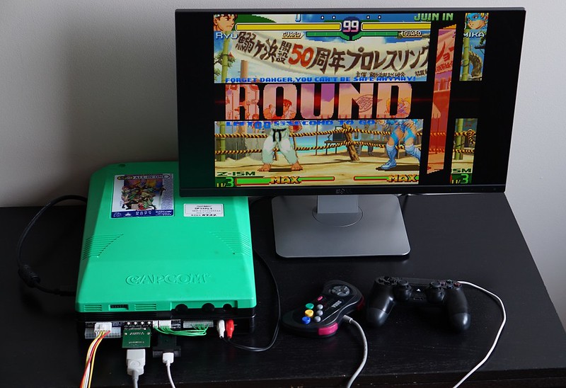
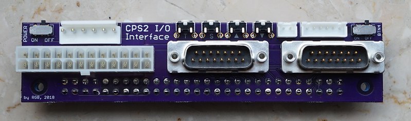
If anybody's looking for a solution to interface the HDMI modded CPS2 without a supergun, I started this project - https://homearcadesystem.wordpress.com/cps2ioi/
The design files and BOM are also available at OSH Park - https://oshpark.com/shared_projects/Zjf0XU71
If anybody's looking for a solution to interface the HDMI modded CPS2 without a supergun, I started this project - https://homearcadesystem.wordpress.com/cps2ioi/
The design files and BOM are also available at OSH Park - https://oshpark.com/shared_projects/Zjf0XU71
Re: CPS2 digital AV interface
Always impressed by the quality and ingenuity of these modules !
Wow.
Wow.
-
AlxUnderBase
- Posts: 33
- Joined: Tue Aug 28, 2018 5:24 am
- Location: Constanta,Romania
- Contact:
Re: CPS2 digital AV interface
This is the perfect setup for CPS2 ! Thank you for all sir !RGB wrote:Installed my CPS2 digital AV, it works a charm!
If anybody's looking for a solution to interface the HDMI modded CPS2 without a supergun, I started this project - https://homearcadesystem.wordpress.com/cps2ioi/
The design files and BOM are also available at OSH Park - https://oshpark.com/shared_projects/Zjf0XU71
Re: CPS2 digital AV interface
We got a handful of kits in today (not as many as expected due to a problem at the manufacturers) so I've sent out invites to the first few folks on the waiting list.
At the moment this is going faster than Wiidual, I would not have expected that
The CPS2 interface looks great, I'll definitely carry those too at some point in the future if I can (with RGBs blessing of course).
At the moment this is going faster than Wiidual, I would not have expected that
The CPS2 interface looks great, I'll definitely carry those too at some point in the future if I can (with RGBs blessing of course).
OSSC Forums - http://www.videogameperfection.com/forums
Please check the Wiki before posting about Morph, OSSC, XRGB Mini or XRGB3 - http://junkerhq.net/xrgb/index.php/Main_Page
Please check the Wiki before posting about Morph, OSSC, XRGB Mini or XRGB3 - http://junkerhq.net/xrgb/index.php/Main_Page
-
cr4zymanz0r

- Posts: 356
- Joined: Sat Oct 19, 2013 6:36 am
Re: CPS2 digital AV interface
Excitedly awaiting my CPS2 HDMI kit (will it come with the shielded/coaxial wire needed for the clock signal?)
As for the CPS2 Interface board, that is pretty nice. Personally, I'd prefer it remove the existing power connectors and just add a barrel connector for some kind of laptop power supply, plus the additional needed DC to DC conversion (kinda mimicking undamned's original CPS2 consolization's power, but externally). However, I have no idea if there'd be enough room to implement the additional power logic without significantly changing the PCB footprint. It'd be pretty nice to just have to tote a laptop power brick if I took the whole CPS2 setup to a friend's house rather than dealing with an arcade or ATX PSU.
As for the CPS2 Interface board, that is pretty nice. Personally, I'd prefer it remove the existing power connectors and just add a barrel connector for some kind of laptop power supply, plus the additional needed DC to DC conversion (kinda mimicking undamned's original CPS2 consolization's power, but externally). However, I have no idea if there'd be enough room to implement the additional power logic without significantly changing the PCB footprint. It'd be pretty nice to just have to tote a laptop power brick if I took the whole CPS2 setup to a friend's house rather than dealing with an arcade or ATX PSU.
Re: CPS2 digital AV interface
It doesn't come with this but it's pretty easy to find.will it come with the shielded/coaxial wire needed for the clock signal?
OSSC Forums - http://www.videogameperfection.com/forums
Please check the Wiki before posting about Morph, OSSC, XRGB Mini or XRGB3 - http://junkerhq.net/xrgb/index.php/Main_Page
Please check the Wiki before posting about Morph, OSSC, XRGB Mini or XRGB3 - http://junkerhq.net/xrgb/index.php/Main_Page
Re: CPS2 digital AV interface
@marqs: So you've redone some of the audio implementation you say and make it lock at 48kHz? Is there any chance you could backport this to the 1.0 version of the board? Otherwise, how hard would it be to replace the 1.0 board with a later version, given that I got mine installed by zeruel85 and it traveled quite a long way
Re: CPS2 digital AV interface
Yes, it should be possible to backport audio ASRC feature to v1.0 board. I'll take a look into that once the launch preparations for the new version are done.mtn360 wrote:@marqs: So you've redone some of the audio implementation you say and make it lock at 48kHz? Is there any chance you could backport this to the 1.0 version of the board? Otherwise, how hard would it be to replace the 1.0 board with a later version, given that I got mine installed by zeruel85 and it traveled quite a long way
Re: CPS2 digital AV interface
I finally got around to completing / programming / installing the first version of this board. This thing is amazing! Thanks so much Marqs.


Re: CPS2 digital AV interface
Audio ASRC feature has been now ported on cps3 and rev1 branches. The former means there's no more need for a dedicated chip for cps3 installations which should save a bit of cost and installation time.
Re: CPS2 digital AV interface
Thanks Marqs for updating the V1. I've updated to firmware 0.51 and everything works as expected.
-
cr4zymanz0r
- Posts: 356
- Joined: Sat Oct 19, 2013 6:36 am
Re: CPS2 digital AV interface
Well after the postal service had my package in the void for 2 weeks with no updates, it finally started moving and arrived today. I installed the HDMI board and the video works great, but I'm getting no sound at all. I've tried a monitor with built in speakers and my game room TV connected to my receiver. I've also tried 2 different HDMI cords and verified analog audio is still working fine.
My phone didn't take great pics, but here's some https://imgur.com/a/1kaomD6
I'm assuming the solder points on the TDA1543 DAC are the only ones I need to be concerned with if sound isn't working.
When looking at the DAC in my pictures pins 1,2,3,4 are facing you in that order, which are BCK, WS, DATA, Ground.
I made sure each of those was soldered to the corresponding BCK, WS, DAT, GND pads on the HDMI board.
I triple checked continuity with a multimeter, even switched from the thin solid core wire I was using to stranded floppy cable wires, re-verified continuity, and nothing changed. Can anyone help? I'm kinda at a loss as to why sound isn't working on HDMI.
EDIT: I figured it out. I didn't find it noted anywhere in install instructions (that I saw at least) but I looked at the PDF schematic and deduced that J3, J5, and J6 needed to be closed to pass through the digital audio signals. Now I'm left wondering what J7 is for
Re: CPS2 digital AV interface
Bridging J3, J5, J6 is at least mentioned on the instructions on the github page. J7 is only relevant when the dedicated ASRC chip is installed, so it's no more mentioned in the instructions.cr4zymanz0r wrote:EDIT: I figured it out. I didn't find it noted anywhere in install instructions (that I saw at least) but I looked at the PDF schematic and deduced that J3, J5, and J6 needed to be closed to pass through the digital audio signals. Now I'm left wondering what J7 is for
Pre-assembled boards should be now available on VGP, and in future possibly from selected US & Japan resellers as well.
Re: CPS2 digital AV interface
Planned adapter for installing the board on CPS1:
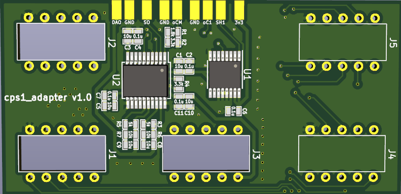
CPS1 video circuitry is very similar to CPS2, but audio is a bit different. YM2151 OPM has digital output which can be directly connected to main cps2_digiav board, but OKI6295 ADPCM only has analog output which is digitized by an audio ADC on the adapter board.
CPS1 video circuitry is very similar to CPS2, but audio is a bit different. YM2151 OPM has digital output which can be directly connected to main cps2_digiav board, but OKI6295 ADPCM only has analog output which is digitized by an audio ADC on the adapter board.

Re: CPS2 digital AV interface
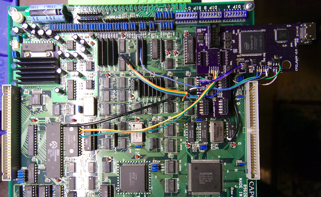
CPS1 installation with the adapter board:
Re: CPS2 digital AV interface
Great work Markus and thanks to RetroRGB for his help too. I'll definitely stock the CPS1 adapters too and, what a perfect excuse to buy some CPS1 hardware
OSSC Forums - http://www.videogameperfection.com/forums
Please check the Wiki before posting about Morph, OSSC, XRGB Mini or XRGB3 - http://junkerhq.net/xrgb/index.php/Main_Page
Please check the Wiki before posting about Morph, OSSC, XRGB Mini or XRGB3 - http://junkerhq.net/xrgb/index.php/Main_Page