Hrm, I was super excited for the CPS1 version, but that looks very precarious. I'm guessing you have no intention of a more CPS1-specific board which isn't going to jut out so far from the PCB form factor?
BTW, I tried to capture footage from my CPS2HDMI via a black magic intensity and it was completely hopeless at locking onto the signal. Do we have a list of capture solutions which support the CPS2HDMI? Including audio+video
CPS2 digital AV interface

Re: CPS2 digital AV interface
At least for pre-assembled boards it's most convenient and economical to stick with one common design even though it's not most optimal fit for CPS1/3. That's assuming majority of the buyers are installing it to CPS2, so things might change if there's suddenly a massive interest in a model optimized for CPS1.fluxcore wrote:Hrm, I was super excited for the CPS1 version, but that looks very precarious. I'm guessing you have no intention of a more CPS1-specific board which isn't going to jut out so far from the PCB form factor?
The only "non-standard" charastetistic is 59.64Hz, otherwise the output should be de-facto 1080p. Perhaps that's out of the range supported by black magic intensity which would be a bummer but hardly surprising consideríng the inflexibility of capture cards (compared to TVs/monitors).fluxcore wrote:TW, I tried to capture footage from my CPS2HDMI via a black magic intensity and it was completely hopeless at locking onto the signal. Do we have a list of capture solutions which support the CPS2HDMI? Including audio+video

Re: CPS2 digital AV interface
Do you have a part number for the through hole JAMMA connector on this board. I can't seem to find one for the life of me.RGB wrote:Installed my CPS2 digital AV, it works a charm!
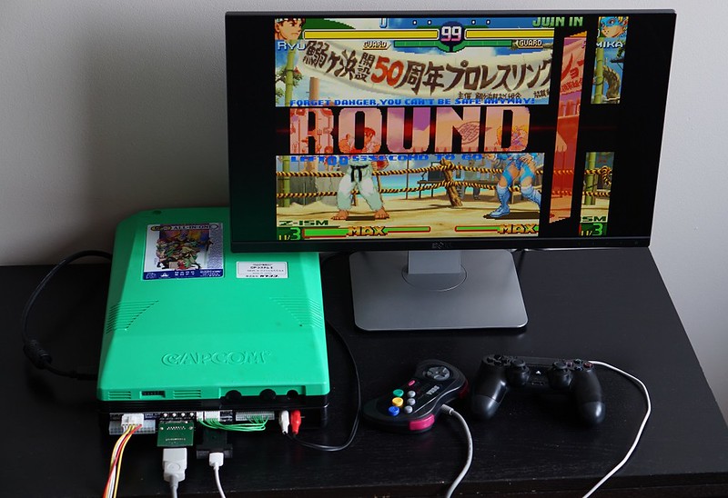
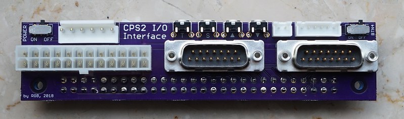
If anybody's looking for a solution to interface the HDMI modded CPS2 without a supergun, I started this project - https://homearcadesystem.wordpress.com/cps2ioi/
The design files and BOM are also available at OSH Park - https://oshpark.com/shared_projects/Zjf0XU71
plus ça change,
plus c'est la même chose,
The more that things change,
The more they stay the same.- RUSH- Circumstances
I install and sell mods at arthrimus.com | SNES RGB Bypass+Dejitter available now! | Watch me live stream my work on YouTube
plus c'est la même chose,
The more that things change,
The more they stay the same.- RUSH- Circumstances
I install and sell mods at arthrimus.com | SNES RGB Bypass+Dejitter available now! | Watch me live stream my work on YouTube
Re: CPS2 digital AV interface
This seems like a suitable one, but I can't confirm.Arthrimus wrote:Do you have a part number for the through hole JAMMA connector on this board. I can't seem to find one for the life of me.
Re: CPS2 digital AV interface
Yes that one works. Thanks for tracking it down, don't know why I was having so much trouble finding it.marqs wrote:This seems like a suitable one, but I can't confirm.Arthrimus wrote:Do you have a part number for the through hole JAMMA connector on this board. I can't seem to find one for the life of me.
Incidentally the PCB house that I used to manufacture the I/O board for me has a minimum order quantity of five copies of the PCB, so I went ahead and assembled five of the I/O boards and kick harnesses. I only need one so if anybody else wants one I have four more I/O boards and Kick Harness adapters available. PM if interested.

plus ça change,
plus c'est la même chose,
The more that things change,
The more they stay the same.- RUSH- Circumstances
I install and sell mods at arthrimus.com | SNES RGB Bypass+Dejitter available now! | Watch me live stream my work on YouTube
plus c'est la même chose,
The more that things change,
The more they stay the same.- RUSH- Circumstances
I install and sell mods at arthrimus.com | SNES RGB Bypass+Dejitter available now! | Watch me live stream my work on YouTube
Re: CPS2 digital AV interface
Preliminary code and instructions for CPS1 installation are now in repo. Adaptation for CPS1 video is complete, as well as for YM2151 OPM. The remaining part is to figure out the best place to extract MSM6295 voice audio (which unfortunately isn't used on the board I have).
Minor changes to cps1_adapter will be made as well (there is also an option to make a L-shaped adapter PCB to prevent anything sticking outside of CPS1 A-board boundary). It should be also noted that the current adapter board can be properly mounted on certain A-board revisions only (89626A-4 and probably its DASH version too). A different adapter would be needed for 88617A revisions.
Minor changes to cps1_adapter will be made as well (there is also an option to make a L-shaped adapter PCB to prevent anything sticking outside of CPS1 A-board boundary). It should be also noted that the current adapter board can be properly mounted on certain A-board revisions only (89626A-4 and probably its DASH version too). A different adapter would be needed for 88617A revisions.
Re: CPS2 digital AV interface
@Arthrimus, I'd like to snag one of those boards from ya. Can't PM you. Maybe it's because I'm new?
Re: CPS2 digital AV interface
Nice, nice!marqs wrote:Preliminary code and instructions for CPS1 installation are now in repo. Adaptation for CPS1 video is complete, as well as for YM2151 OPM. The remaining part is to figure out the best place to extract MSM6295 voice audio (which unfortunately isn't used on the board I have).
Minor changes to cps1_adapter will be made as well (there is also an option to make a L-shaped adapter PCB to prevent anything sticking outside of CPS1 A-board boundary). It should be also noted that the current adapter board can be properly mounted on certain A-board revisions only (89626A-4 and probably its DASH version too). A different adapter would be needed for 88617A revisions.
I'm guessing due to the way you've written this, that the clock differences between DASH and non-dash (i.e. 10MHz vs 12MHz) won't cause issues for the HDMI device?
Re: CPS2 digital AV interface
The PPU clock is still 16MHz so I don't expect any difference in video timings.fluxcore wrote:I'm guessing due to the way you've written this, that the clock differences between DASH and non-dash (i.e. 10MHz vs 12MHz) won't cause issues for the HDMI device?
Re: CPS2 digital AV interface
I wouldn't mind grabbing one or two of those IO and kick harnesses off you Arthrimus. Do you have any left?
Arthrimus wrote:Yes that one works. Thanks for tracking it down, don't know why I was having so much trouble finding it.marqs wrote:This seems like a suitable one, but I can't confirm.Arthrimus wrote:Do you have a part number for the through hole JAMMA connector on this board. I can't seem to find one for the life of me.
Incidentally the PCB house that I used to manufacture the I/O board for me has a minimum order quantity of five copies of the PCB, so I went ahead and assembled five of the I/O boards and kick harnesses. I only need one so if anybody else wants one I have four more I/O boards and Kick Harness adapters available. PM if interested.
-
Danexmurder

- Posts: 73
- Joined: Mon Feb 26, 2018 3:12 pm
- Location: Frederick, MD
Re: CPS2 digital AV interface
I'm working on my install and have a question about hooking up +5v and Ground. In the instructions they are using an unused ccx terminal. On my motherboard all of the CCX terminals are populated. Can I still just solder them up to the legs of the cap on that spot?
Re: CPS2 digital AV interface
Yes, that's OK. There are also many other places to tap +5V and GND in case those are cumbersome with the caps populated.Danexmurder wrote:I'm working on my install and have a question about hooking up +5v and Ground. In the instructions they are using an unused ccx terminal. On my motherboard all of the CCX terminals are populated. Can I still just solder them up to the legs of the cap on that spot?
-
Danexmurder
- Posts: 73
- Joined: Mon Feb 26, 2018 3:12 pm
- Location: Frederick, MD
Re: CPS2 digital AV interface
Thanks for the info! I almost just ran the wires to the through holes on above the Jamma edge but just ended up soldering to the legs of the capacitor. I wrapped up the rest of the soldering last night. Looking forward to putting it all back together and trying it out tonight or tomorrow. Going to install a Gelid Silent 6 fan while I've got it open.marqs wrote:Yes, that's OK. There are also many other places to tap +5V and GND in case those are cumbersome with the caps populated.Danexmurder wrote:I'm working on my install and have a question about hooking up +5v and Ground. In the instructions they are using an unused ccx terminal. On my motherboard all of the CCX terminals are populated. Can I still just solder them up to the legs of the cap on that spot?
-
Danexmurder
- Posts: 73
- Joined: Mon Feb 26, 2018 3:12 pm
- Location: Frederick, MD
Re: CPS2 digital AV interface
I finished my install and got it up and running last night! It really looks phenomenal on my 4K panel.
The only issue I ran into was that I wasn't getting audio over HDMI. Any suggestions?
Thanks!
Edit:
My jumpers are bridged and I checked continuity with a multimeter.
The only issue I ran into was that I wasn't getting audio over HDMI. Any suggestions?
Thanks!
Edit:
My jumpers are bridged and I checked continuity with a multimeter.
Re: CPS2 digital AV interface
Can you check whether analog audio still works? There was one strange case in which audio (both digital and analog) stopped working after installation which was subsequently resolved by changing coax cable to a better quality one.Danexmurder wrote:The only issue I ran into was that I wasn't getting audio over HDMI. Any suggestions?
-
Danexmurder
- Posts: 73
- Joined: Mon Feb 26, 2018 3:12 pm
- Location: Frederick, MD
Re: CPS2 digital AV interface
I haven't checked the analog audio yet. Good call. I'll try that out tonight and report back. If you have a source for particularly good coax cable please let me know. I just grabbed what I could find on amazon.marqs wrote:Can you check whether analog audio still works? There was one strange case in which audio (both digital and analog) stopped working after installation which was subsequently resolved by changing coax cable to a better quality one.Danexmurder wrote:The only issue I ran into was that I wasn't getting audio over HDMI. Any suggestions?
-
Danexmurder
- Posts: 73
- Joined: Mon Feb 26, 2018 3:12 pm
- Location: Frederick, MD
Re: CPS2 digital AV interface
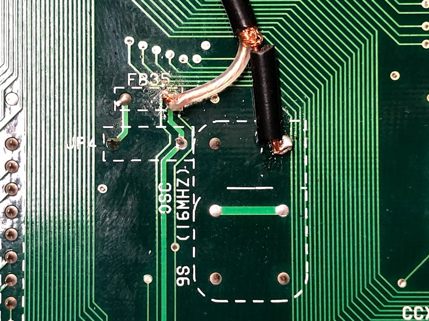
I checked into the analog audio last night and can confirm that it doesn't. I have no audio at all.marqs wrote:Can you check whether analog audio still works? There was one strange case in which audio (both digital and analog) stopped working after installation which was subsequently resolved by changing coax cable to a better quality one.Danexmurder wrote:The only issue I ran into was that I wasn't getting audio over HDMI. Any suggestions?
This is what my Coax installation looks like.
Re: CPS2 digital AV interface
Is the X68000 hardware similar enough to the CPS to make an internal CPS2AV type mod a possibility?
Re: CPS2 digital AV interface
Try disconnecting the coax below oscillator and ensure that analog audio is restored. RG-174 or similar coax should be good for the mod.Danexmurder wrote:I checked into the analog audio last night and can confirm that it doesn't. I have no audio at all.
This is what my Coax installation looks like.
The board is designed for systems with up to 16bit parallel video data and serial (I2S) audio, I'm not sure how close that is to signals you can extract from X68000 internally.xterc wrote:Is the X68000 hardware similar enough to the CPS to make an internal CPS2AV type mod a possibility?
-
Danexmurder
- Posts: 73
- Joined: Mon Feb 26, 2018 3:12 pm
- Location: Frederick, MD
Re: CPS2 digital AV interface
I disconnected below the oscillator and can confirm audio works. I did use RG-174 but I’ve got another coax cable I can try. Should I just do that?marqs wrote:Try disconnecting the coax below oscillator and ensure that analog audio is restored. RG-174 or similar coax should be good for the mod.Danexmurder wrote:I checked into the analog audio last night and can confirm that it doesn't. I have no audio at all.
This is what my Coax installation looks like.The board is designed for systems with up to 16bit parallel video data and serial (I2S) audio, I'm not sure how close that is to signals you can extract from X68000 internally.xterc wrote:Is the X68000 hardware similar enough to the CPS to make an internal CPS2AV type mod a possibility?
Re: CPS2 digital AV interface
Yes, you could try that, and try also to keep cable length at minimum. Can you also check where the clock trace leads on your board? If there is a buffer before some sinks, its output might be a better place to tap clock signal.Danexmurder wrote:I disconnected below the oscillator and can confirm audio works. I did use RG-174 but I’ve got another coax cable I can try. Should I just do that?
-
Danexmurder
- Posts: 73
- Joined: Mon Feb 26, 2018 3:12 pm
- Location: Frederick, MD
Re: CPS2 digital AV interface
I desoldered the old RG-174 and put in some RG-316 instead. I fired it up and it worked right away. Not sure why it didn’t like the other one but that did the trick!marqs wrote:Yes, you could try that, and try also to keep cable length at minimum. Can you also check where the clock trace leads on your board? If there is a buffer before some sinks, its output might be a better place to tap clock signal.Danexmurder wrote:I disconnected below the oscillator and can confirm audio works. I did use RG-174 but I’ve got another coax cable I can try. Should I just do that?

Re: CPS2 digital AV interface
Try using only RG59 cables for digital audio. Everything else will be slightly to completely out of spec and may introduce various issues.
Re: CPS2 digital AV interface
Hi,
I have one of these coming in the mail any day now. I have done some installs of other mods but usually need help with part picking and some clear videos/photos/instructions of the install. I was hoping for some kind of YouTube video showcasing an install of this but couldn't find any. Seems scouring some forums for snap shots of others finished results is all I am coming across. Is there a more detailed / descriptive overview of the install?
Also, anyone have links for the recommended cabling? I see some "RG-174" and "RG-316" on amazon but in a quantity I am sure to never use. Also ribbon cable or gauge of cable recommended for everything else.
-
hugo19941994

- Posts: 40
- Joined: Sat Aug 25, 2018 12:43 pm
- Location: Spain
Re: CPS2 digital AV interface
I installed mine this afternoon and I found the docs in GitHub pretty clear. RGB posted a complete install in another forum as well.
EDIT:
I guess I'll add my own installation pic


EDIT:
I guess I'll add my own installation pic
Re: CPS2 digital AV interface
That's a really nice install!
Do you remember where you got that ribbon cable from? What gauge it is? How about the coaxial cable? Some here seem to have better luck with some than others.
Do you remember where you got that ribbon cable from? What gauge it is? How about the coaxial cable? Some here seem to have better luck with some than others.
-
NoAffinity

- Posts: 1033
- Joined: Mon May 07, 2018 5:27 pm
- Location: Escondido, CA, USA
Re: CPS2 digital AV interface
How are you guys flashing your cyclones? Ive got a usb blaster clone. Have used it on various projects successfully. The most recent was flashing an ossc. I am trying various releases of quartus that supports the cyclone 10. Im updating the blaster driver from the driver library of each release. On my win 10 pc, it blue screens whenever i open the programmer interface in quartus. On my win 7 pc, i get blue screen sometimes. Sometimes im able to get to the point of loading the jic file, but then programming fails. I tried auto detecting the jtag chain (win 7 pc) and quartus resulted in jtag chain not being found. Any help appreciated. Time for a usb blaster II?
Oh and what is maximum resistance the coax can be rated?
Sent from my SM-G955U using Tapatalk
Oh and what is maximum resistance the coax can be rated?
Sent from my SM-G955U using Tapatalk
-
hugo19941994
- Posts: 40
- Joined: Sat Aug 25, 2018 12:43 pm
- Location: Spain
Re: CPS2 digital AV interface
I just went to a local electronics shop and got some 28AWG ribbon cable and asked for some coax cable which can be soldered. It's marked as Emelec Q11-75 (I think it's a local Spanish brand). The cables is not too thick so it wasn't too unwieldy to solder, but seems to work fine.Kavas wrote:Do you remember where you got that ribbon cable from? What gauge it is? How about the coaxial cable? Some here seem to have better luck with some than others.
Mine came pre-flashed from VGP. I guess I'll need to buy a usb blaster to flash the CPS1 fw when my second board arrives.NoAffinity wrote:How are you guys flashing your cyclones?
-
NoAffinity
- Posts: 1033
- Joined: Mon May 07, 2018 5:27 pm
- Location: Escondido, CA, USA
Re: CPS2 digital AV interface
Thanks hugo. I got my board from vgp. Assuming it must also be pre flashed then, but over 24 hours with the question posted on their forum on whether its pre flashed or not and no response. :/
Assuming mine is preflashed, i must be doing something wrong witht he install then. Which brings me back to my question about the coax cable. Had some 75 ohm coax on hand. Looks like coax everyones talking about here is 50 ohm. Could that be the problem?
Sent from my SM-G955U using Tapatalk
Assuming mine is preflashed, i must be doing something wrong witht he install then. Which brings me back to my question about the coax cable. Had some 75 ohm coax on hand. Looks like coax everyones talking about here is 50 ohm. Could that be the problem?
Sent from my SM-G955U using Tapatalk
Re: CPS2 digital AV interface
I am interested in trying the CPS1 branch of the project. I was looking into how to hook it up. I am confused about the audio. It appears that two I2S bus are going to the same pins of the FPGA. I have looked at the schematic, pictures, and Quartus pinout. Does audio really work if WS and BCK are tied together from the YM-2151 and the WM8782?
This is the path the signals appear to take:
OKI M6295 DAO --> WM8782 AINL/AINR
YM2151 oCM --> WM8782 MCLK
YM2151 SO --> I2S_DAT pad --> FPGA SDOUT pin 11
YM2151 oC1 --> I2S_BCK pad --> FPGA BCKO pin 22
YM2151 SH1 --> I2S_WS pad --> FPGA LRCLKO pin 10
YM2151 SH2 --> unused
WM8782 DOUT --> FPGA VSync pin 28
WM8782 BCLK--> FPGA BCKO pin 22
WM8782 LRCLK --> 74LVC112 --> FPGA LRCLKO pin 10
I am also confused what the 74LVC112 is accomplishing.
Should each audio signal have a separate pin of the FPGA?
Great work and thank you for making it open source!