
That's your last option to RGB that set but you will need an amp to drive it properly.
Tim sells a board which would suit this, but usually direct feed into the neckboard is a Pita with substandard results.
TV RGB mod thread
Re: TV RGB mod thread
Hmm, I see what you mean. Maybe I better open my Samsung CL21Z30MQ and see if it has a proper Jungle IC.Syntax wrote:That's your last option to RGB that set but you will need an amp to drive it properly.
Tim sells a board which would suit this, but usually direct feed into the neckboard is a Pita with substandard results.
Re: TV RGB mod thread
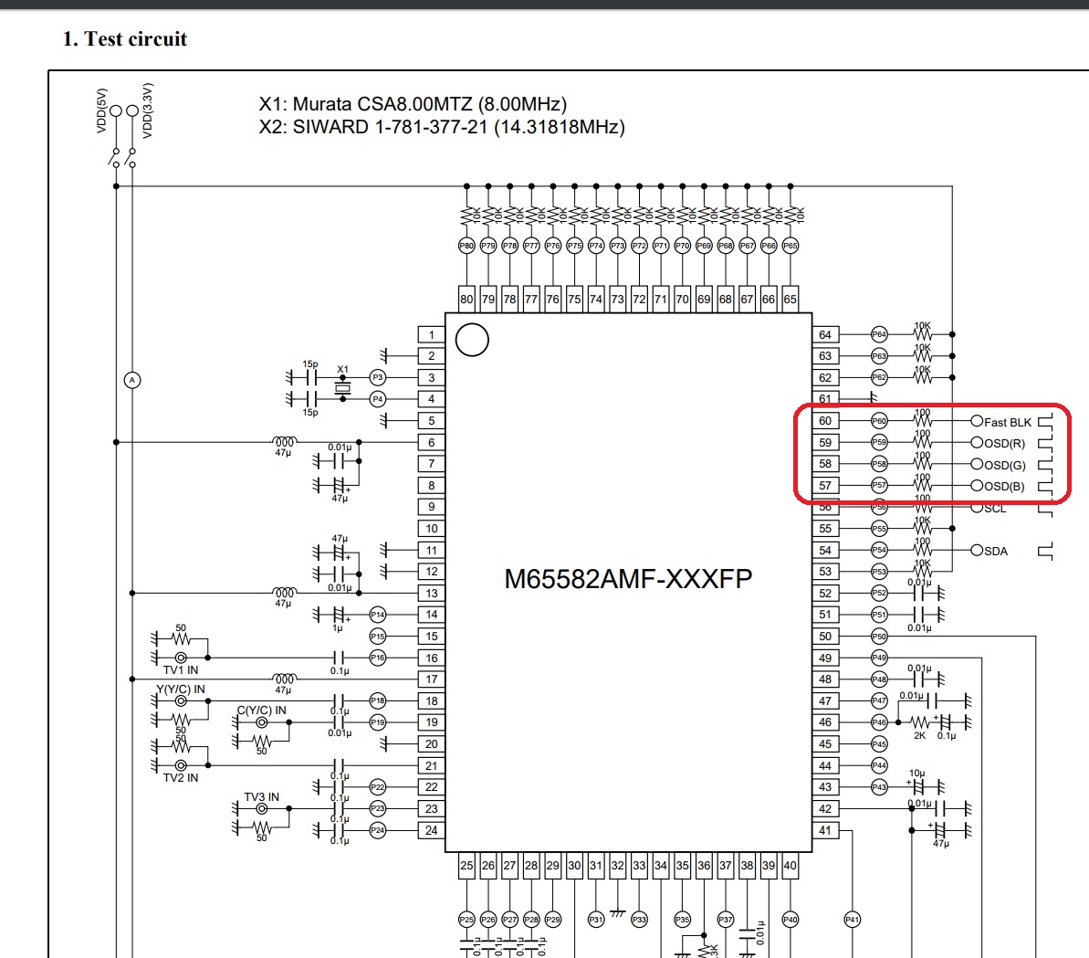
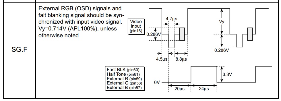
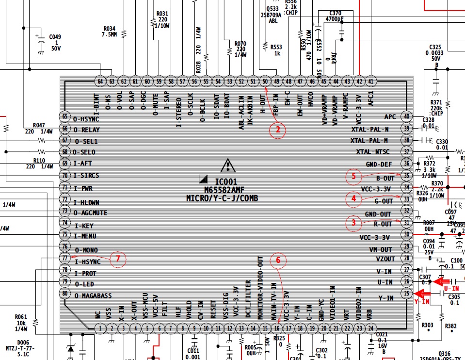
Interestingly the chip seems to support it but the RGB and Blanking pins specified in the datasheet are used for other purposes in this set.Syntax wrote:Look for data on you jungle M65582AMF
___________________________________________________
MarkOZLAD
OSD/External RGB Mux Diagram
OSD/External RGB Mux Resistor Value Table 0.7Vp-p : 0.5Vp-p
"Imagine toggle switch OSD modding a TV in 2019" - maxtherabbit
MarkOZLAD
OSD/External RGB Mux Diagram
OSD/External RGB Mux Resistor Value Table 0.7Vp-p : 0.5Vp-p
"Imagine toggle switch OSD modding a TV in 2019" - maxtherabbit
Re: TV RGB mod thread
Hi, so i have moved on to my second consumer CRT. The Samsung CL21Z30MQ
Jungle IC: TDA12005PQ/N1FCO
Service manual: http://diagramas.diagramasde.com/otros/ ... 20K16B.pdf
Could someone indicate where I should solder the RGB from JAMMA/VGA output, ground and sync?
Actual image with rpi3 > HDMI > component transcoder
https://image.ibb.co/kPkVAb/ki_coco_crt.jpg
Thanks
Jungle IC: TDA12005PQ/N1FCO
Service manual: http://diagramas.diagramasde.com/otros/ ... 20K16B.pdf
Could someone indicate where I should solder the RGB from JAMMA/VGA output, ground and sync?
Actual image with rpi3 > HDMI > component transcoder
https://image.ibb.co/kPkVAb/ki_coco_crt.jpg
Thanks
Re: TV RGB mod thread
Page 50.
Pins 67 to 70.
Pretty sure these are a PIP hack.
Pins 67 to 70.
Pretty sure these are a PIP hack.
Re: TV RGB mod thread
Many thanks for the help. This is my first CRT hack so there are many things i dont understand. Trying to study as much as i can. Also sorry for my english.
Is pin 67 of my Jungle IC (TDA12005PQ N1FCO) the "blanking pin"?
https://imgur.com/a/rjyOj
Is pin 67 of my Jungle IC (TDA12005PQ N1FCO) the "blanking pin"?
https://imgur.com/a/rjyOj
Re: TV RGB mod thread
Have a look at the very last page of your service manual. This TV's chassis is designed to have the option for two scart ports. One of them RGB capable.xprmntl wrote:Many thanks for the help. This is my first CRT hack so there are many things i dont understand. Trying to study as much as i can. Also sorry for my english.
Is pin 67 of my Jungle IC (TDA12005PQ N1FCO) the "blanking pin"?
https://imgur.com/a/rjyOj
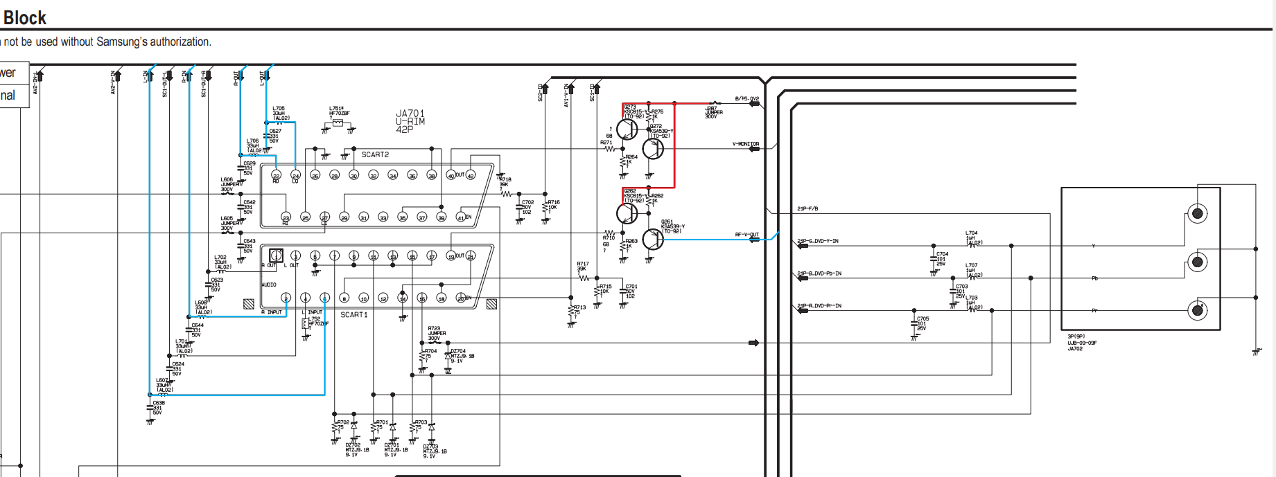
Inpsect your TV chassis near the component inputs (JA702). You should see a place where the scart adapter was to be soldered in. Possibly instead of the component inputs.
It should be possible to solder your scart wiring there.
You will need to use a multimeter to check for components missing, mostly they will be jumpers or resistors. With the multimeter, trace where the signals go from the scart port to the Jungle chip. If you come to dead end, check the schematic for what is missing and add them.
___________________________________________________
MarkOZLAD
OSD/External RGB Mux Diagram
OSD/External RGB Mux Resistor Value Table 0.7Vp-p : 0.5Vp-p
"Imagine toggle switch OSD modding a TV in 2019" - maxtherabbit
MarkOZLAD
OSD/External RGB Mux Diagram
OSD/External RGB Mux Resistor Value Table 0.7Vp-p : 0.5Vp-p
"Imagine toggle switch OSD modding a TV in 2019" - maxtherabbit
-
Enforcer831
- Posts: 1
- Joined: Sun Oct 01, 2017 4:08 am
Re: TV RGB mod thread
I’m looking to mod a Phillips 27PT5445/37. From the schematics I have found, it seems that is used a TDA9377 chip with no inputs for the OSD since that is generated internal to the chip. However , the component lines run to the pins on the chip that according to the data sheet should work for RGB. Any one have any experience with this or a similar chip before I start poking around. I was reading that I may have to jump onto the i2c bus to flip a bit but hopefully just applying a voltage to a pin would work as well. Thanks for the help!
Re: TV RGB mod thread
I followed the termination instructions in the link. 330ohm in line and about 600ohm to ground and the picture is now bright and clear.MarkOZLAD wrote:Came across this link today.
The Jungle in the TV is LA76814K, I figure this should be very similar to the LA76810A in the NEC I am working on. Also a similar generic Chinese chassis.
Part way down he talks about the way he configured his RGB inputs' impedance. I'm going to attempt a similar thing/experiment and see how I go.
What a slice of luck to find this post!
Oh, the OSD works perfectly at the same time as RGB too. Adding the 330ohm resistance to the RGB means the OSD doesn't get drowned out now.
___________________________________________________
MarkOZLAD
OSD/External RGB Mux Diagram
OSD/External RGB Mux Resistor Value Table 0.7Vp-p : 0.5Vp-p
"Imagine toggle switch OSD modding a TV in 2019" - maxtherabbit
MarkOZLAD
OSD/External RGB Mux Diagram
OSD/External RGB Mux Resistor Value Table 0.7Vp-p : 0.5Vp-p
"Imagine toggle switch OSD modding a TV in 2019" - maxtherabbit
Re: TV RGB mod thread
I think I found a TV that can take RGB without modding?
There's a Panasonic TV here in Brazil, model 29FJ30L for the 29" model.
This is from the service manual:
INSSW2 50 2nd RGB / YUV insertion input
R2/VIN 51 2nd R input / V (R-Y) input / PR input
G2/YIN 52 2nd G input / Y input
B2/UIN 53 2nd B input / U (B-Y) input / PB input
The numbers are the main CI pins. Even the blanking pin is the same.
I tried doing RGB directly on the Y U V inputs and sync going with an Y cable to the Y input. The tv can see the sync and the image is visible but with the wrong colors.
I don't have the remote to enter the service menu to see if there's a toggle that can switch from YUV to RGB.
https://www.electronica-pt.com/esquema/ ... 30l-16084/
Here is the service manual, could someone take a look at it?
I guess if there's no option in the service menu it's just a matter of blanking the correct pin.
Am I wrong assuming this is possible? This would result in a single switch with 5v going to the correct pin and enabling RGB.
Not sure but blaking pin 55 would enable RGB?
"BLKIN 55 black current input / V-guard input"
CapivaraGamer
http://capivaragamer.com.br
http://capivaragamer.com.br
Re: TV RGB mod thread
I'm playing with a Sony high def 1080i set that has rca RGB hv VGA input.
Service manual says only 24/31hz compatible but we know that's balls.
If I plug into either Rgbhv or the component, and use RGB with sync on green I get a decent picture that seems reddish.
It won't sync via h or v.
This is the first time I've tried RGsB into composite so I was not sure if it's what happens.
Re: TV RGB mod thread
fandangos wrote:I think I found a TV that can take RGB without modding?
There's a Panasonic TV here in Brazil, model 29FJ30L for the 29" model.
This is from the service manual:
INSSW2 50 2nd RGB / YUV insertion input
R2/VIN 51 2nd R input / V (R-Y) input / PR input
G2/YIN 52 2nd G input / Y input
B2/UIN 53 2nd B input / U (B-Y) input / PB input
The numbers are the main CI pins. Even the blanking pin is the same.
I tried doing RGB directly on the Y U V inputs and sync going with an Y cable to the Y input. The tv can see the sync and the image is visible but with the wrong colors.
I don't have the remote to enter the service menu to see if there's a toggle that can switch from YUV to RGB.
https://www.electronica-pt.com/esquema/ ... 30l-16084/
Here is the service manual, could someone take a look at it?
I guess if there's no option in the service menu it's just a matter of blanking the correct pin.
Am I wrong assuming this is possible? This would result in a single switch with 5v going to the correct pin and enabling RGB.
Not sure but blaking pin 55 would enable RGB?
"BLKIN 55 black current input / V-guard input"
Wire a 10k pot up properly for that blanking pin. It will have 3 states.
Re: TV RGB mod thread
I'll try that.Syntax wrote:
Wire a 10k pot up properly for that blanking pin. It will have 3 states.
Just checking if my thinking is correct:
I'll get 10k pot resistor that has 3 legs. Solder 5v to the first leg, second leg to GND, third leg to Pin 55.
Is that correct?
And what states are those you mentioned?
CapivaraGamer
http://capivaragamer.com.br
http://capivaragamer.com.br
Re: TV RGB mod thread
Go back a page or 2 and look at the picture I posted before you blow something up lol.fandangos wrote:I'll try that.Syntax wrote:
Wire a 10k pot up properly for that blanking pin. It will have 3 states.
Just checking if my thinking is correct:
I'll get 10k pot resistor that has 3 legs. Solder 5v to the first leg, second leg to GND, third leg to Pin 55.
Is that correct?
And what states are those you mentioned?
-
rx7turbo233

- Posts: 40
- Joined: Wed Sep 20, 2017 3:59 am
sony kv24fs120 rgb mod help
hi i wanna rgb mod a kv24fs120 sony tv i would like to know if im able to mod this tv or not it has a M65582AMF and a rgb amplifier but i cant figure how to add the rgb wires to the tv if you can help i would appreciate it thanks
Re: TV RGB mod thread
I saw it. The thing is on my setup I use a female scart connector to RCA ( R G B Sync Audio L R) that I use to hook my PVM and BVM with BNC to female RCA plugs.Syntax wrote: Go back a page or 2 and look at the picture I posted before you blow something up lol.
In the example you made you use 5v from the console but this won't be possible here.
That's why I wanted to be sure I won't mess anything up.
I have to tap 5v somewhere. There's 5v going to the CI that has the YUV/RGB inputs. Can I tap it there?
GND is easy to find.
And the most important, in the service manual I posted, I know it's in portuguese but the pins are labeled and described in English. So I just wanted to make sure that Pin 55 is actually blanking because there's a INSW pin that I believe is used for YUV?
I saw you did a TV like that that uses component going to the same pins as RGB.
So am I correct to assume all this? Or am I making some mistake here?
EDIT: also, do I have to lift the Pin 55 leg before soldering the 10k pot leg to it?
EDIT 2: This are the pins descriptions and the voltage they expect:
INSSW2 50 2nd RGB / YUV insertion input - 2.5v (this would blank for YUV?)
BCLIN 54 beam current limiter input - 2v ??
BLKIN 55 black current input / V-guard input 5.3v
This all for the IC 601 that is a TDA9592N64BT, which I can't find any diagram online.
CapivaraGamer
http://capivaragamer.com.br
http://capivaragamer.com.br
Re: TV RGB mod thread
Don't touch bclin or blkin. That's beam and black levels.
I know it looks like the word blanking but that's there to confuse you
The pot gets wired ground left side blanking pin middle 5v right.
The 5v doesn't matter where you get it from.
You can use 7v or 9v even but should be careful to start with the pot turned down and stop when blanking occurs.
I'll look at your jungke in a minute but if there us not a inssw1 then I would say that your inssw2 will work like
0-.4v nothing or
2.5v YUV
5v RGB
Or here's hoping anyway.
Edit
Ok read the jungle pdf.
If all goes to plan you could plug RGB into the component plugs and sync into a composite channel, change to that channel then turn the blanking pot till you get a picture.
The whole mod would only require a single pole switch to power the blanking pot.
Double edit
That cable you use, did you buy it or make it?
I made one the other day with the thought that using rca to Bnc adapters would make it very useful when testing component/RGB tvs and still work for my pvms.
Does it have another use?
Re: TV RGB mod thread
Great, I'll try this as soon as possible. I have to travel to my wife's parents houseSyntax wrote:Don't touch bclin or blkin. That's beam and black levels.
I know it looks like the word blanking but that's there to confuse you
The pot gets wired ground left side blanking pin middle 5v right.
The 5v doesn't matter where you get it from.
You can use 7v or 9v even but should be careful to start with the pot turned down and stop when blanking occurs.
I'll look at your jungke in a minute but if there us not a inssw1 then I would say that your inssw2 will work like
0-.4v nothing or
2.5v YUV
5v RGB
Or here's hoping anyway.
Edit
Ok read the jungle pdf.
If all goes to plan you could plug RGB into the component plugs and sync into a composite channel, change to that channel then turn the blanking pot till you get a picture.
The whole mod would only require a single pole switch to power the blanking pot.
Double edit
That cable you use, did you buy it or make it?
I made one the other day with the thought that using rca to Bnc adapters would make it very useful when testing component/RGB tvs and still work for my pvms.
Does it have another use?
That adapter I made it myself. I used a scart to scart adapter. Opened the box, removed one side. Used a component cable that had the matching colors for R G B, soldered it and closed the box. So it's like a small black box with the cables dangling from it. It works great for me here.
Edit: where did you find the diagram for the jungle IC? I honestly can't find anything on TDA 9592.
CapivaraGamer
http://capivaragamer.com.br
http://capivaragamer.com.br
Re: TV RGB mod thread
Just on this, I always use a Scart to RCA breakout when doing the initial modding prior to installation of the scart port. I find RCA ports etc are dirt cheap and easy to use so i build my test rigs using them.Syntax wrote: That cable you use, did you buy it or make it?
I made one the other day with the thought that using rca to Bnc adapters would make it very useful when testing component/RGB tvs and still work for my pvms.
Does it have another use?
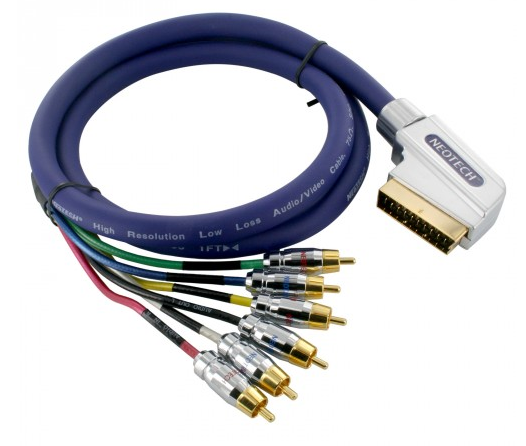
I was lucky enough to snaffle a scart to RCA component video + sync + audio from a recycling centre for $4. It is awesome. I've seen them online for sale for $75 (tell 'im he's dreamin'!). They are rare though.
However, one of the Foxtel style Scart to Component video adapters can easily be found and modified. Just open up the scart end and desolder one of the audio lines and solder it to the sync/composite video and video ground instead. Sure the sound becomes mono but it's not important when you're modding.
This is the breakout cable I got for $4.. Score!!
Here's a pic of my latest test rig.
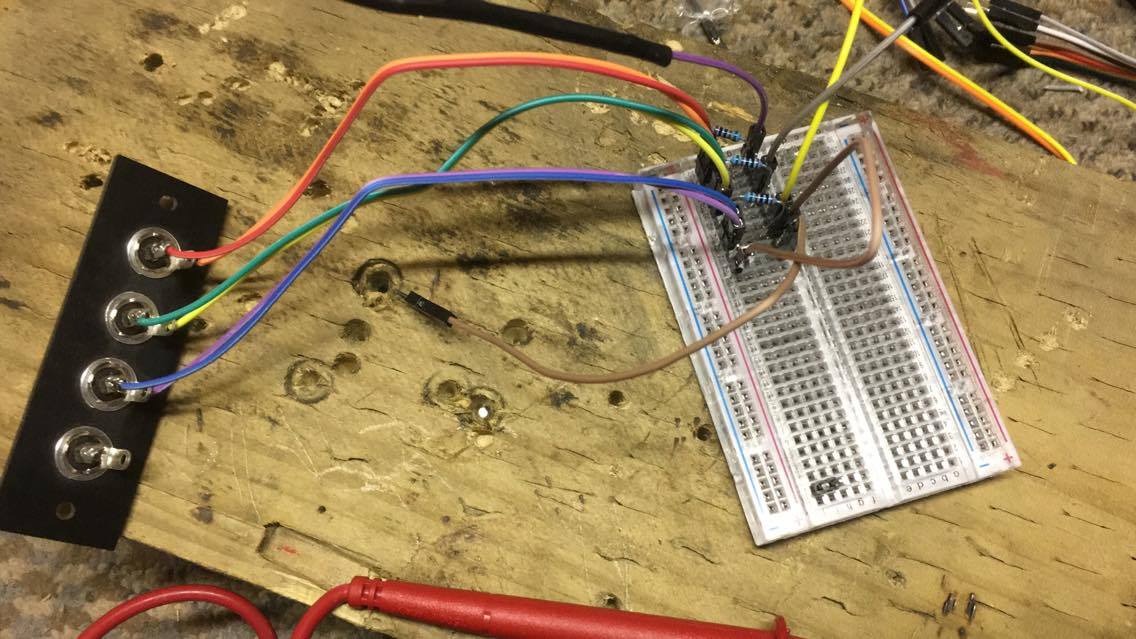
I ran out of jumper wires, the outputs should be red,green and blue!
___________________________________________________
MarkOZLAD
OSD/External RGB Mux Diagram
OSD/External RGB Mux Resistor Value Table 0.7Vp-p : 0.5Vp-p
"Imagine toggle switch OSD modding a TV in 2019" - maxtherabbit
MarkOZLAD
OSD/External RGB Mux Diagram
OSD/External RGB Mux Resistor Value Table 0.7Vp-p : 0.5Vp-p
"Imagine toggle switch OSD modding a TV in 2019" - maxtherabbit
Re: TV RGB mod thread
https://m.ebay.com.au/itm/SCART-to-6RCA ... 5730579012
Cut the scart off this and wired a $2.50 female scart from Tims store. Hard to source the female ones now days..
Cut the scart off this and wired a $2.50 female scart from Tims store. Hard to source the female ones now days..
-
rx7turbo233
- Posts: 40
- Joined: Wed Sep 20, 2017 3:59 am
Re: TV RGB mod thread
im trying to see how i would go about rgb modding a sony kv24fs120 it uses the same hardware as a kv27fs120 im just trying to see if i can take the micro contrioler out of the system and wire my rgb to the rgb outputs on the chip it has a rgb amp futher down the line i was just wanting to see if that would work or not
-
rx7turbo233
- Posts: 40
- Joined: Wed Sep 20, 2017 3:59 am
Re: TV RGB mod thread
their is the ic data sheet , but cant find any info on the chassis SCC- S61L-A
http://www.datasheetarchive.com/pdf/dow ... 2AMF-XXXFP
http://www.datasheetarchive.com/pdf/dow ... 2AMF-XXXFP
Re: TV RGB mod thread
Service manual is here.rx7turbo233 wrote:their is the ic data sheet , but cant find any info on the chassis SCC- S61L-A
http://www.datasheetarchive.com/pdf/dow ... 2AMF-XXXFP
I don't know how to mod this set. If you look back up the page you will see that I noted the M65582AMF chip appears to have RGB inputs but they appear to be re-purposed in this set.
___________________________________________________
MarkOZLAD
OSD/External RGB Mux Diagram
OSD/External RGB Mux Resistor Value Table 0.7Vp-p : 0.5Vp-p
"Imagine toggle switch OSD modding a TV in 2019" - maxtherabbit
MarkOZLAD
OSD/External RGB Mux Diagram
OSD/External RGB Mux Resistor Value Table 0.7Vp-p : 0.5Vp-p
"Imagine toggle switch OSD modding a TV in 2019" - maxtherabbit
Re: TV RGB mod thread
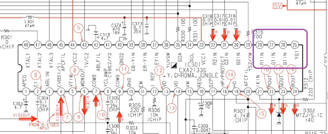
Conveniently, I just picked up a KV-27V42 from a friend and was looking to mod it. Looking through the service manual, I figured it would be nearly the same process as the 27s42, because their JC diagrams look identical. This will be my first time doing an RGB mod tho so any pics/tips/guidance that you have would be highly appreciated. For some reason, I've taken it upon myself to learn about all of this instead of studying for midterms.mikejmoffitt wrote:Just did a KV-27V42 with a CXA2133 (I think). Looks great, worked first time, more or less the same process as the S42. I'll post pics and details later, and comb the thread for stuff to update the first post.
Re: TV RGB mod thread
I wish I could get my hands on one just so I could try using the other RGB input....dakattack wrote:Conveniently, I just picked up a KV-27V42 from a friend and was looking to mod it. Looking through the service manual, I figured it would be nearly the same process as the 27s42, because their JC diagrams look identical. This will be my first time doing an RGB mod tho so any pics/tips/guidance that you have would be highly appreciated. For some reason, I've taken it upon myself to learn about all of this instead of studying for midterms.mikejmoffitt wrote:Just did a KV-27V42 with a CXA2133 (I think). Looks great, worked first time, more or less the same process as the S42. I'll post pics and details later, and comb the thread for stuff to update the first post.
Don't think I'll find any in Australia.
___________________________________________________
MarkOZLAD
OSD/External RGB Mux Diagram
OSD/External RGB Mux Resistor Value Table 0.7Vp-p : 0.5Vp-p
"Imagine toggle switch OSD modding a TV in 2019" - maxtherabbit
MarkOZLAD
OSD/External RGB Mux Diagram
OSD/External RGB Mux Resistor Value Table 0.7Vp-p : 0.5Vp-p
"Imagine toggle switch OSD modding a TV in 2019" - maxtherabbit
Re: TV RGB mod thread
Why? We have plenty on cxa jungles here that do exactly the same.MarkOZLAD wrote:I wish I could get my hands on one just so I could try using the other RGB input....dakattack wrote:Conveniently, I just picked up a KV-27V42 from a friend and was looking to mod it. Looking through the service manual, I figured it would be nearly the same process as the 27s42, because their JC diagrams look identical. This will be my first time doing an RGB mod tho so any pics/tips/guidance that you have would be highly appreciated. For some reason, I've taken it upon myself to learn about all of this instead of studying for midterms.mikejmoffitt wrote:Just did a KV-27V42 with a CXA2133 (I think). Looks great, worked first time, more or less the same process as the S42. I'll post pics and details later, and comb the thread for stuff to update the first post.
Don't think I'll find any in Australia.
The pinout is identical to one I've done here but a different jungle.
Re: TV RGB mod thread
Hey you're right, this pinout is the same on the CXA2159s I did on the BG-3R chassis.Syntax wrote:Why? We have plenty on cxa jungles here that do exactly the same.
The pinout is identical to one I've done here but a different jungle.
I don't think these TVs need the OSD lines snipped at all.
___________________________________________________
MarkOZLAD
OSD/External RGB Mux Diagram
OSD/External RGB Mux Resistor Value Table 0.7Vp-p : 0.5Vp-p
"Imagine toggle switch OSD modding a TV in 2019" - maxtherabbit
MarkOZLAD
OSD/External RGB Mux Diagram
OSD/External RGB Mux Resistor Value Table 0.7Vp-p : 0.5Vp-p
"Imagine toggle switch OSD modding a TV in 2019" - maxtherabbit
Re: TV RGB mod thread
Cxa chips with secondary RGB inputs don't need OSD lines snipped, you know this. They just need blanking.MarkOZLAD wrote:Hey you're right, this pinout is the same on the CXA2159s I did on the BG-3R chassis.Syntax wrote:Why? We have plenty on cxa jungles here that do exactly the same.
The pinout is identical to one I've done here but a different jungle.
I don't think these TVs need the OSD lines snipped at all.
Also BG-3r does not have secondary inputs for RGB, we covered this 3 pages ago when I realised the OSD and teletext are connected to the same input.
Go open a BG-3r and try you muxing method and report back but before then go get some sleep :p
Re: TV RGB mod thread
Hehe, I could do with some sleep, I won't debate that!Syntax wrote:Cxa chips with secondary RGB inputs don't need OSD lines snipped, you know this. They just need blanking.MarkOZLAD wrote:Hey you're right, this pinout is the same on the CXA2159s I did on the BG-3R chassis.Syntax wrote:Why? We have plenty on cxa jungles here that do exactly the same.
The pinout is identical to one I've done here but a different jungle.
I don't think these TVs need the OSD lines snipped at all.
Also BG-3r does not have secondary inputs for RGB, we covered this 3 pages ago when I realised the OSD and teletext are connected to the same input.
Go open a BG-3r and try you muxing method and report back but before then go get some sleep :p
I've done a BG-3R, the OSD works at same time as RGB but is dim. I reckon that could be solved with some tweaking. I'd like another shot at it.
___________________________________________________
MarkOZLAD
OSD/External RGB Mux Diagram
OSD/External RGB Mux Resistor Value Table 0.7Vp-p : 0.5Vp-p
"Imagine toggle switch OSD modding a TV in 2019" - maxtherabbit
MarkOZLAD
OSD/External RGB Mux Diagram
OSD/External RGB Mux Resistor Value Table 0.7Vp-p : 0.5Vp-p
"Imagine toggle switch OSD modding a TV in 2019" - maxtherabbit
Re: TV RGB mod thread
earlier in the thread,MarkOZLAD wrote:I wish I could get my hands on one just so I could try using the other RGB input....dakattack wrote:Conveniently, I just picked up a KV-27V42 from a friend and was looking to mod it. Looking through the service manual, I figured it would be nearly the same process as the 27s42, because their JC diagrams look identical. This will be my first time doing an RGB mod tho so any pics/tips/guidance that you have would be highly appreciated. For some reason, I've taken it upon myself to learn about all of this instead of studying for midterms.mikejmoffitt wrote:Just did a KV-27V42 with a CXA2133 (I think). Looks great, worked first time, more or less the same process as the S42. I'll post pics and details later, and comb the thread for stuff to update the first post.
Don't think I'll find any in Australia.
I thought the v42 would be the same way? Is there a workaround that allows RGB1 to function?mikejmoffitt wrote:Regarding the RGB1 input on the S42's jungle IC, the microcontroller must first enable this input. Just wiring to it won't work (which I tried).
Also if anyone can tell me if K-SCARTX-024 from Mouser would be acceptable to use as the mounted input for the TV, that would be awesome too. Thanks.